
Summary of Contents for York OPTIVIEW
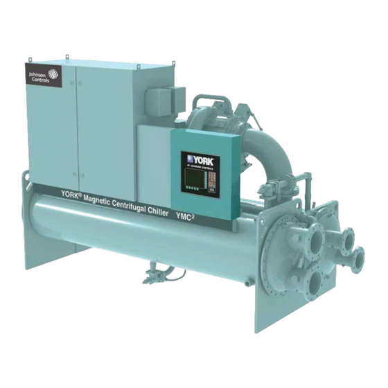
- Page 1 OPTIVIEW™ CONTROL CENTER OPERATION MANUAL Supersedes: 160.78-O2 (1112) Form 160.78-O2 (517) OPTIVIEW™ CONTROL CENTER MODEL A LD14000 R-134a Issue Date: May 22, 2017...
- Page 2 FORM 160.78-O2 ISSUE DATE: 5/22/2017 IMPORTANT! READ BEFORE PROCEEDING! GENERAL SAFETY GUIDELINES This equipment is a relatively complicated apparatus. which it is situated, as well as severe personal injury or During rigging, installation, operation, maintenance, death to themselves and people at the site. or service, individuals may be exposed to certain com- This document is intended for use by owner-authorized ponents or conditions including, but not limited to:...
- Page 3 MANUAL DESCRIPTION FORM NUMBER Installation 160.78-N1 Unit Re-assembly 160.78-N2 Centrifugal Chiller Long Term Storage 50.20-NM5 Field Connections 160.78-PW1 Unit Wiring and Field Control Modifications 160.78-PW2 Unit Renewal Parts 160.78-RP1 OptiView Renewal Parts 160.78-RP2 Unit Operations and Maintenance Manual 160.78-O1 JOHNSON CONTROLS...
- Page 4 FORM 160.78-O2 ISSUE DATE: 5/22/2017 SYSTEM NOMENCLATURE Y M C 2 - S 0756 A A YORK Mod Level Magnetic Bearing Refrigerant R-134a Centrifugal Chiller Capacity in KW S = Single Stage T = Two Stage COMPRESSOR NOMENCLATURE M1 B - 197 F A A...
-
Page 5: Table Of Contents
FORM 160.78-O2 ISSUE DATE: 5/22/2017 TABLE OF CONTENTS SECTION 1 - DESCRIPTION OF SYSTEM AND FUNDAMENTALS OF OPERATION .......... 9 SECTION 2 - OPTIVIEW CONTROL CENTER INTRODUCTION ................13 Home Screen ..............................18 System Screen ..............................21 Evaporator Screen ............................23 Condenser Screen ............................27 Head Pressure Control Screen ........................29... - Page 6 Chiller ..........................9 FIGURE 2 - Refrigerant Flow-Thru Chiller.......................10 FIGURE 3 - Compressor Prerotation Vanes ......................11 FIGURE 4 - Optiview Control Center........................14 FIGURE 5 - Home Screen ............................18 FIGURE 6 - System Screen ............................21 FIGURE 7 - Evaporator Screen ..........................23 FIGURE 8 - Condenser Screen ..........................27...
- Page 7 FORM 160.78-O2 ISSUE DATE: 5/22/2017 LIST OF FIGURES (CONT'D) FIGURE 54 - Drive Logic Board ..........................142 FIGURE 55 - Rectifier Side Of The Power Unit.....................142 FIGURE 56 - Printers ............................146 FIGURE 57 - Sample Printout (Status)........................150 FIGURE 58 - Sample Printout (Setpoints) ......................152 FIGURE 59 - Sample Printout (Schedule) ......................154 FIGURE 60 - Sample Printout (Sales Order)......................154 FIGURE 61 - Sample Printout (History).........................155...
- Page 8 FORM 160.78-O2 ISSUE DATE: 5/22/2017 THIS PAGE INTENTIONALLY LEFT BLANK JOHNSON CONTROLS...
-
Page 9: Section 1 - Description Of System And Fundamentals Of Operation
The chiller with the OptiView control other cases. Watch for notes regarding the separate va- center is applied with a Variable Speed Drive. -
Page 10: Figure 2 - Refrigerant Flow-Thru Chiller
FORM 160.78-O2 SECTION 1 - DESCRIPTION OF SYSTEM AND FUNDAMENTALS OF OPERATION ISSUE DATE: 5/22/2017 ROTOR COOLING GAS VENT (GAS PATH REV A COMPRESSOR COMPRESSORS ONLY) HOT GAS BYPASS VALVE PRE-ROTATION VANES DISCHARGE CHECK VALVE SUCTION DISCHARGE LIQUID LEVEL ISOLATION VALVE VALVE EVAPORATOR... -
Page 11: Figure 3 - Compressor Prerotation Vanes
FORM 160.78-O2 SECTION 1 - DESCRIPTION OF SYSTEM AND FUNDAMENTALS OF OPERATION ISSUE DATE: 5/22/2017 CAPACITY CONTROL The speed at which the compressor rotates establishes the pressure differential that the chiller can operate against. As speed is reduced, the chiller power use is reduced. - Page 12 FORM 160.78-O2 SECTION 1 - DESCRIPTION OF SYSTEM AND FUNDAMENTALS OF OPERATION ISSUE DATE: 5/22/2017 THIS PAGE INTENTIONALLY LEFT BLANK JOHNSON CONTROLS...
-
Page 13: Section 2 - Optiview Control Center Introduction
Building Automation and optional hot gas bypass. It has the ability to limit System (BAS), YORK Chillers not only work well indi- motor current and shell pressures. vidually, but also as a team. This new protocol allows in-... -
Page 14: Figure 4 - Optiview Control Center
SECTION 2 - OPTIVIEW CONTROL CENTER INTRODUCTION ISSUE DATE: 5/22/2017 29348A FIGURE 4 - OPTIVIEW CONTROL CENTER The OptiView control center display is highlighted by a Cursor Arrow keys are provid- full screen graphics display. This display is nested with- ed to allow movement on in a standard keypad, and is surrounded by “soft”... - Page 15 FORM 160.78-O2 SECTION 2 - OPTIVIEW CONTROL CENTER INTRODUCTION ISSUE DATE: 5/22/2017 The safety stop button must be rotated clockwise to re- with an Access Level of VIEW. This will allow the lease the stop condition. The safety stop is not intended user to navigate to most screens and observe the val- for normal shutdown of the chiller.
- Page 16 FORM 160.78-O2 SECTION 2 - OPTIVIEW CONTROL CENTER INTRODUCTION ISSUE DATE: 5/22/2017 Pressing the ▲ key, sets the entry value to the de- Home Screen (Page 18) fault for that setpoint. Pressing the ▼ key, clears System Screen (Page 21) the present entry. The ◄ key is a backspace key Evaporator Screen (Page 23) and causes the entry point to move back one Condenser Screen (Page 27) space.
-
Page 17: Table 1 - Analog Input Ranges
FORM 160.78-O2 SECTION 2 - OPTIVIEW CONTROL CENTER INTRODUCTION ISSUE DATE: 5/22/2017 LANGUAGES guage. If a language other than English is being dis- The screens can be displayed in various languages. played, an English speaking person should navigate Language selection is done on the USER Screen. The to the USER Screen (using the preceding Navigation desired language is selected from those available. -
Page 18: Home Screen
FORM 160.78-O2 SECTION 2 - OPTIVIEW CONTROL CENTER INTRODUCTION ISSUE DATE: 5/22/2017 HOME SCREEN LD14844c FIGURE 5 - HOME SCREEN OVERVIEW Input % Full Load Amps This displays the percentage of full load amps utilized When the chiller system is powered on, the above de- by the system. - Page 19 FORM 160.78-O2 SECTION 2 - OPTIVIEW CONTROL CENTER INTRODUCTION ISSUE DATE: 5/22/2017 ERATOR and will allow the customer to change all Warning Reset of the setpoints required to operate the chiller system. Access Level Required: OPERATOR The OPERATOR access level reverts to the VIEW Use of this key acknowledges a warning condition and level after 10 continuous minutes without a keypress.
- Page 20 FORM 160.78-O2 SECTION 2 - OPTIVIEW CONTROL CENTER INTRODUCTION ISSUE DATE: 5/22/2017 A detailed view of the motor and VSD parameters. This allows programming of the Current Limit and the Pulldown Demand Limit values. Setpoints This screen provides a single location to program the most common system setpoints.
-
Page 21: System Screen
FORM 160.78-O2 SECTION 2 - OPTIVIEW CONTROL CENTER INTRODUCTION ISSUE DATE: 5/22/2017 SYSTEM SCREEN LD14849a FIGURE 6 - SYSTEM SCREEN OVERVIEW Condenser Liquid Temperature - Leaving Displays the temperature of the liquid as it leaves the This screen gives a general overview of common chill- condenser. - Page 22 FORM 160.78-O2 SECTION 2 - OPTIVIEW CONTROL CENTER INTRODUCTION ISSUE DATE: 5/22/2017 Condenser Pressure PROGRAMMABLE Displays the refrigerant pressure in the condenser. There are no programmable fields on this screen. Condenser Saturation Temperature NAVIGATION Displays the saturation temperature in the condenser.
-
Page 23: Evaporator Screen
FORM 160.78-O2 SECTION 2 - OPTIVIEW CONTROL CENTER INTRODUCTION ISSUE DATE: 5/22/2017 EVAPORATOR SCREEN LD14846a FIGURE 7 - EVAPORATOR SCREEN OVERVIEW Evaporator Pressure Displays the present refrigerant pressure in the evapo- This screen displays a cutaway view of the chiller rator. - Page 24 FORM 160.78-O2 SECTION 2 - OPTIVIEW CONTROL CENTER INTRODUCTION ISSUE DATE: 5/22/2017 Leaving Chilled Liquid Temperature Setpoints PROGRAMMABLE – Restart Local Leaving Chilled Liquid Temperature - Displays the Leaving Chilled Liquid Temperature at Setpoint which the chiller will restart after it has shutdown on Access Level Required: OPERATOR LEAVING CHILLED LIQUID –...
- Page 25 FORM 160.78-O2 SECTION 2 - OPTIVIEW CONTROL CENTER INTRODUCTION ISSUE DATE: 5/22/2017 Leaving Chilled Liquid Temperature Cycling Leaving Chilled Liquid Temperature Cycling Offset - Shutdown Offset - Restart Access Level Required: OPERATOR Access Level Required: OPERATOR This value allows the user to specify the Leaving...
- Page 26 FORM 160.78-O2 SECTION 2 - OPTIVIEW CONTROL CENTER INTRODUCTION ISSUE DATE: 5/22/2017 THIS PAGE INTENTIONALLY LEFT BLANK JOHNSON CONTROLS...
-
Page 27: Condenser Screen
FORM 160.78-O2 SECTION 2 - OPTIVIEW CONTROL CENTER INTRODUCTION ISSUE DATE: 5/22/2017 CONDENSER SCREEN LD14847b FIGURE 8 - CONDENSER SCREEN OVERVIEW Condenser Small Temperature Difference Displays the difference between the Condenser Refrig- This screen displays a cutaway view of the chiller con- erant temperature and the Leaving Condenser Liquid denser. - Page 28 FORM 160.78-O2 SECTION 2 - OPTIVIEW CONTROL CENTER INTRODUCTION ISSUE DATE: 5/22/2017 Condenser Liquid Flow Switch NAVIGATION Indicates whether flow is present in the condenser. Home Causes an instant return to the Home Screen. Condenser Liquid Pump (Run/Stop) Displays the command presently sent by the control cen- Refrigerant Level Control ter to the Condenser Liquid Pump run contacts.
-
Page 29: Head Pressure Control Screen
FORM 160.78-O2 SECTION 2 - OPTIVIEW CONTROL CENTER INTRODUCTION ISSUE DATE: 5/22/2017 HEAD PRESSURE CONTROL SCREEN LD14335a FIGURE 9 - HEAD PRESSURE CONTROL SCREEN Leaving Condenser Liquid Temperature OVERVIEW Displays the temperature of the liquid as it leaves the This screen displays all parameters related to the Head standard condenser tube bundle. - Page 30 FORM 160.78-O2 SECTION 2 - OPTIVIEW CONTROL CENTER INTRODUCTION ISSUE DATE: 5/22/2017 PROGRAMMABLE Head Pressure Control - P Sets the Proportional Gain of the Head Pressure Control Head Pressure Setpoint (0.00 to 5.00; default 2.00). Use the Change Setpoints Sets the pressure differential to which the Control key as described above to select/enter this setpoint.
-
Page 31: Refrigerant Level Control Screen
FORM 160.78-O2 SECTION 2 - OPTIVIEW CONTROL CENTER INTRODUCTION ISSUE DATE: 5/22/2017 REFRIGERANT LEVEL CONTROL SCREEN LD14852b FIGURE 10 - REFRIGERANT LEVEL CONTROL SCREEN OVERVIEW The following fields require login access level of SERVICE. Service technicians re- This screen displays a cutaway view of the chiller con-... - Page 32 FORM 160.78-O2 SECTION 2 - OPTIVIEW CONTROL CENTER INTRODUCTION ISSUE DATE: 5/22/2017 Active Level Setpoint PROGRAMMABLE Displays the refrigerant level target that the chiller Level Setpoint is controlling to. This value is determined as level Specifies the desired refrigerant level to be maintained setpoint or ramp up target, depending on state.
-
Page 33: Refrigerant Level Control Setpoints Screen
FORM 160.78-O2 SECTION 2 - OPTIVIEW CONTROL CENTER INTRODUCTION ISSUE DATE: 5/22/2017 REFRIGERANT LEVEL CONTROL SETPOINTS SCREEN LD14852c FIGURE 11 - REFRIGERANT LEVEL CONTROL SETPOINTS SCREEN OVERVIEW Transition Time Remaining Same as Refrigerant Level Control Screen. This screen is available at service level access and al-... - Page 34 FORM 160.78-O2 SECTION 2 - OPTIVIEW CONTROL CENTER INTRODUCTION ISSUE DATE: 5/22/2017 Ramp Time NAVIGATION Access Level Required: ADMIN Home After the chiller has been running for the level con- Causes an instant return to the Home Screen. trol startup delay time, if the refrigerant level is less...
-
Page 35: Compressor Screen
FORM 160.78-O2 SECTION 2 - OPTIVIEW CONTROL CENTER INTRODUCTION ISSUE DATE: 5/22/2017 COMPRESSOR SCREEN LD16112 FIGURE 12 - COMPRESSOR SCREEN - GAS PATH REVISION "A" LD14853c FIGURE 13 - COMPRESSOR SCREEN - GAS PATH REVISION "B" OVERVIEW This screen displays a cutaway view of the chiller com- cates whether the chiller is presently in a RUN condi- tion. - Page 36 FORM 160.78-O2 SECTION 2 - OPTIVIEW CONTROL CENTER INTRODUCTION ISSUE DATE: 5/22/2017 DISPLAY ONLY PROGRAMMABLE There are no programmable fields on this screen. Discharge Temperature Displays the temperature of the refrigerant in its gas- eous state at discharge of the compressor as it travels NAVIGATION to the condenser.
-
Page 37: Magnetic Bearing Controller Screen
FORM 160.78-O2 SECTION 2 - OPTIVIEW CONTROL CENTER INTRODUCTION ISSUE DATE: 5/22/2017 MAGNETIC BEARING CONTROLLER SCREEN LD14843d FIGURE 14 - MAGNETIC BEARING CONTROLLER SCREEN OVERVIEW W3 (Current) Displays the magnetizing current to the lower bearing This screen displays the orientation of the magnetic on the radial axis designated “W”... - Page 38 FORM 160.78-O2 SECTION 2 - OPTIVIEW CONTROL CENTER INTRODUCTION ISSUE DATE: 5/22/2017 W24 Position [MBC Outputs] MBC Fault (LED) Displays the shaft position in micrometers from center Indicates the MBC fault contacts are opened, indicat- along the radial axis designated “W” for the Opposite ing a fault, by the control Digital Input.
-
Page 39: Magnetic Bearing Controller Details Screen
FORM 160.78-O2 SECTION 2 - OPTIVIEW CONTROL CENTER INTRODUCTION ISSUE DATE: 5/22/2017 MAGNETIC BEARING CONTROLLER DETAILS SCREEN LD14843e FIGURE 15 - MAGNETIC BEARING CONTROLLER DETAILS SCREEN OVERVIEW VW24 Vibration Displays the vibration amplitude at rotational frequen- This screen displays the orientation of the magnetic... - Page 40 FORM 160.78-O2 SECTION 2 - OPTIVIEW CONTROL CENTER INTRODUCTION ISSUE DATE: 5/22/2017 • V2 (Current) PROGRAMMABLE There are no programmable fields on this screen. • Z2 (Current) • V4 (Current) NAVIGATION • W4 (Current) Home [MBC Status] AVR (LED) Causes immediate return to the Home Screen.
-
Page 41: Mbc Event Log Screen
FORM 160.78-O2 SECTION 2 - OPTIVIEW CONTROL CENTER INTRODUCTION ISSUE DATE: 5/22/2017 MBC EVENT LOG SCREEN LD14843d FIGURE 16 - MBC EVENT LOG SCREEN OVERVIEW NAVIGATION This screen displays the event history logs saved in the Home Magnetic Bearing Control Program. - Page 42 FORM 160.78-O2 SECTION 2 - OPTIVIEW CONTROL CENTER INTRODUCTION ISSUE DATE: 5/22/2017 THIS PAGE INTENTIONALLY LEFT BLANK JOHNSON CONTROLS...
-
Page 43: Surge Screen
FORM 160.78-O2 SECTION 2 - OPTIVIEW CONTROL CENTER INTRODUCTION ISSUE DATE: 5/22/2017 SURGE SCREEN LD14853 FIGURE 17 - SURGE SCREEN OVERVIEW setpoint. When it reaches the COUNT WINDOW min- utes, the number of surge events in the oldest minute is... - Page 44 FORM 160.78-O2 SECTION 2 - OPTIVIEW CONTROL CENTER INTRODUCTION ISSUE DATE: 5/22/2017 PROGRAMMABLE Surge Sensitivity Access Level Required: SERVICE Shutdown (Enabled/Disabled) Allows the user to define the surge detection sensitiv- Access Level Required: OPERATOR ity of the Surge Protection feature. Selectable over the Allows the user to select whether the chiller will shut- range of 0.3 to 1.3;...
-
Page 45: Variable Geometry Diffuser Screen
FORM 160.78-O2 SECTION 2 - OPTIVIEW CONTROL CENTER INTRODUCTION ISSUE DATE: 5/22/2017 VARIABLE GEOMETRY DIFFUSER SCREEN LD16113 FIGURE 18 - VARIABLE GEOMETRY DIFFUSER SCREEN - GAS PATH REVISION "A" LD16114 FIGURE 19 - VARIABLE GEOMETRY DIFFUSER SCREEN - GAS PATH REVISION "B"... - Page 46 FORM 160.78-O2 SECTION 2 - OPTIVIEW CONTROL CENTER INTRODUCTION ISSUE DATE: 5/22/2017 DISPLAY ONLY Surge Detected (LED) Illuminates for 5 seconds each time a surge is detected. Active Stall Voltage Displays the Stall Detector output voltage (x.xxVdc), VGD Count as received by the Microboard, from the stall board.
- Page 47 FORM 160.78-O2 SECTION 2 - OPTIVIEW CONTROL CENTER INTRODUCTION ISSUE DATE: 5/22/2017 PROGRAMMABLE NAVIGATION [VGD] Open (Manual) Home This key puts the VGD in manual mode and sends an Causes an instant return to the Home Screen. open command to the VGD.
- Page 48 FORM 160.78-O2 SECTION 2 - OPTIVIEW CONTROL CENTER INTRODUCTION ISSUE DATE: 5/22/2017 THIS PAGE INTENTIONALLY LEFT BLANK JOHNSON CONTROLS...
-
Page 49: Variable Geometry Diffuser Setpoints Screen
FORM 160.78-O2 SECTION 2 - OPTIVIEW CONTROL CENTER INTRODUCTION ISSUE DATE: 5/22/2017 VARIABLE GEOMETRY DIFFUSER SETPOINTS SCREEN LD16115 FIGURE 20 - VARIABLE GEOMETRY DIFFUSER SETPOINTS SCREEN - GAS PATH REVISION "A" LD16116 FIGURE 21 - VARIABLE GEOMETRY DIFFUSER SETPOINTS SCREEN - GAS PATH REVISION "B"... - Page 50 FORM 160.78-O2 SECTION 2 - OPTIVIEW CONTROL CENTER INTRODUCTION ISSUE DATE: 5/22/2017 DISPLAY ONLY Surge Detected (LED) Illuminates for 5 seconds each time a surge is detected. Active Stall Voltage Displays the Stall Detector output voltage (x.xxVdc), VGD Count as received by the Microboard.
- Page 51 FORM 160.78-O2 SECTION 2 - OPTIVIEW CONTROL CENTER INTRODUCTION ISSUE DATE: 5/22/2017 Low Limit PRV Offset - Gas Path Revision "A" Only In the Stall Reacting State, the VGD is driven closed If the VGD control is in the Stall Waiting state and the...
- Page 52 FORM 160.78-O2 SECTION 2 - OPTIVIEW CONTROL CENTER INTRODUCTION ISSUE DATE: 5/22/2017 THIS PAGE INTENTIONALLY LEFT BLANK JOHNSON CONTROLS...
-
Page 53: Variable Geometry Diffuser Calibration Screen
FORM 160.78-O2 SECTION 2 - OPTIVIEW CONTROL CENTER INTRODUCTION ISSUE DATE: 5/22/2017 VARIABLE GEOMETRY DIFFUSER CALIBRATION SCREEN LD14856c FIGURE 22 - VARIABLE GEOMETRY DIFFUSER CALIBRATION SCREEN - GAS PATH REVISION "A" LD14856d FIGURE 23 - VARIABLE GEOMETRY DIFFUSER CALIBRATION SCREEN - GAS PATH REVISION "B"... - Page 54 FORM 160.78-O2 SECTION 2 - OPTIVIEW CONTROL CENTER INTRODUCTION ISSUE DATE: 5/22/2017 DISPLAY ONLY PROGRAMMABLE VGD Opening (LED) Set 100% VGD - Gas Path Revision “A” Only Indicates the VGD is opening. Accepts the present VGD feedback voltage as the 100% calibration value.
-
Page 55: Pre-Rotation Vanes Calibration Screen Applies To Gas Path Revision "A" Only
FORM 160.78-O2 SECTION 2 - OPTIVIEW CONTROL CENTER INTRODUCTION ISSUE DATE: 5/22/2017 PRE-ROTATION VANES CALIBRATION SCREEN APPLIES TO GAS PATH REVISION "A" ONLY LD16117 FIGURE 24 - PRE-ROTATION VANES CALIBRATION SCREEN OVERVIEW PRV Feedback Voltage Displays the pre-rotation vanes position potentiometer This screen displays a cutaway view of the chiller com- feedback voltage. - Page 56 FORM 160.78-O2 SECTION 2 - OPTIVIEW CONTROL CENTER INTRODUCTION ISSUE DATE: 5/22/2017 THIS PAGE INTENTIONALLY LEFT BLANK JOHNSON CONTROLS...
-
Page 57: Capacity Controls Screen
FORM 160.78-O2 SECTION 2 - OPTIVIEW CONTROL CENTER INTRODUCTION ISSUE DATE: 5/22/2017 CAPACITY CONTROLS SCREEN LD14842a FIGURE 25 - CAPACITY CONTROLS SCREEN - GAS PATH REVISION "A" LD14842b FIGURE 26 - CAPACITY CONTROLS SCREEN - GAS PATH REVISION "B" OVERVIEW anti-surge control. - Page 58 FORM 160.78-O2 SECTION 2 - OPTIVIEW CONTROL CENTER INTRODUCTION ISSUE DATE: 5/22/2017 DISPLAY ONLY Active LCHLT Setpoint Displays the active temperature setpoint to which the Evaporator Pressure chiller is set to control liquid leaving the evaporator. Displays the pressure in the evaporator.
- Page 59 FORM 160.78-O2 SECTION 2 - OPTIVIEW CONTROL CENTER INTRODUCTION ISSUE DATE: 5/22/2017 Load Limit PROGAMMABLE Displays if any load limiting control is acting on the Select VSD Control temperature control output to the capacity control de- Access Level Required: SERVICE vices.
- Page 60 FORM 160.78-O2 SECTION 2 - OPTIVIEW CONTROL CENTER INTRODUCTION ISSUE DATE: 5/22/2017 Decrease NAVIGATION Access Level Required: SERVICE Home Pressing this button will set the selected device’s state Causes and instant return to the Home Screen. to Manual if it had been in Auto and will decrease the device’s present control command by an amount equal...
-
Page 61: Variable Speed Drive Screen
FORM 160.78-O2 SECTION 2 - OPTIVIEW CONTROL CENTER INTRODUCTION ISSUE DATE: 5/22/2017 VARIABLE SPEED DRIVE SCREEN LD14858c FIGURE 27 - VARIABLE SPEED DRIVE SCREEN - GAS PATH REVISION "A" LD14858d FIGURE 28 - VARIABLE SPEED DRIVE SCREEN - GAS PATH REVISION "B"... - Page 62 FORM 160.78-O2 SECTION 2 - OPTIVIEW CONTROL CENTER INTRODUCTION ISSUE DATE: 5/22/2017 VSD Fault (LED) Input kVA Displays the supply kva measured by the VSD. Indicates the VSD is reporting a fault. Input % Full Load Amps Input Power Factor...
- Page 63 Access Level Required: SERVICE Allows the user to reset the cumulative Kilowatt Hours Moves to a subscreen that provides information and to zero (0). Service Technicians refer to YORK YMC setpoints pertinent to the Motor Monitoring feature. Service Manual (Form 160.78-M2).
- Page 64 FORM 160.78-O2 SECTION 2 - OPTIVIEW CONTROL CENTER INTRODUCTION ISSUE DATE: 5/22/2017 THIS PAGE INTENTIONALLY LEFT BLANK JOHNSON CONTROLS...
-
Page 65: Variable Speed Drive (Vsd) Details Screen
DISPLAY ONLY • 9 = Manual Precharge VSD Command • 10 = Man Pre-Regulate The command from OptiView control to the VSD. • 11 = Soft Shutdown Commands are as follows: • 12 = Precharge Re-init • 0 = Off • 13 = Check DCCT... - Page 66 FORM 160.78-O2 SECTION 2 - OPTIVIEW CONTROL CENTER INTRODUCTION ISSUE DATE: 5/22/2017 VSD Output Frequency Rectifier Baseplate Temperature (L1, L2, L3) Displays the present output frequency to the motor. Displays the VSD input rectifier baseplate tempera- tures at each phase.
- Page 67 FORM 160.78-O2 SECTION 2 - OPTIVIEW CONTROL CENTER INTRODUCTION ISSUE DATE: 5/22/2017 NAVIGATION Home Causes an instant return to the Home screen. Causes an instant return to the Home screen. Setpoints Access Level Required: ADMIN Moves to the subscreen which provides for entry and edit of VSD input and control setpoints.
- Page 68 FORM 160.78-O2 SECTION 2 - OPTIVIEW CONTROL CENTER INTRODUCTION ISSUE DATE: 5/22/2017 THIS PAGE INTENTIONALLY LEFT BLANK JOHNSON CONTROLS...
-
Page 69: Motor Details Screen
This screen displays information pertinent to the Motor Motor Run (LED) Temperature Monitoring feature. The feature consists Illuminates when the Optiview control center is com- of motor winding temperature and motor housing tem- manding the motor to run. perature. Also, individual winding temperature sensors can be disabled on this screen. - Page 70 FORM 160.78-O2 SECTION 2 - OPTIVIEW CONTROL CENTER INTRODUCTION ISSUE DATE: 5/22/2017 %Input Full Load Amps Displays the input current as a percentage of chiller full Returns to the VSD Screen. load amps. Features Applicable to Gas Path Revisions Output Frequency "B"...
- Page 71 FORM 160.78-O2 SECTION 2 - OPTIVIEW CONTROL CENTER INTRODUCTION ISSUE DATE: 5/22/2017 Manual Increment Access Level Required: SERVICE Sets the increment by which the motor cooling valve command will be adjusted when in manual control Open/Close Access Level Required: SERVICE Changes the motor cooling valve command by one unit of the manual increment setting.
- Page 72 FORM 160.78-O2 SECTION 2 - OPTIVIEW CONTROL CENTER INTRODUCTION ISSUE DATE: 5/22/2017 THIS PAGE INTENTIONALLY LEFT BLANK JOHNSON CONTROLS...
-
Page 73: Setpoints Screen
FORM 160.78-O2 SECTION 2 - OPTIVIEW CONTROL CENTER INTRODUCTION ISSUE DATE: 5/22/2017 SETPOINTS SCREEN LD14860a FIGURE 32 - SETPOINTS SCREEN ing the building. This value is calculated by subtract- OVERVIEW ing the Leaving Chilled Liquid Temperature Cycling This screen provides a convenient location for pro- Offset –... - Page 74 FORM 160.78-O2 SECTION 2 - OPTIVIEW CONTROL CENTER INTRODUCTION ISSUE DATE: 5/22/2017 PROGRAMMABLE a range of 1°F to 64°F below the setpoint, to a mini- mum cutout of 36°F (water), 34°F (water with Smart Local Leaving Chilled Liquid Temperature - Freeze enabled) or 6°F (brine).
- Page 75 FORM 160.78-O2 SECTION 2 - OPTIVIEW CONTROL CENTER INTRODUCTION ISSUE DATE: 5/22/2017 Pulldown Demand Limit NAVIGATION Access Level Required: OPERATOR Home Allows the user to specify the current limit value (as Causes an instant return to the Home Screen. a percentage of Full Load Amps) to which the chiller...
- Page 76 FORM 160.78-O2 SECTION 2 - OPTIVIEW CONTROL CENTER INTRODUCTION ISSUE DATE: 5/22/2017 THIS PAGE INTENTIONALLY LEFT BLANK JOHNSON CONTROLS...
-
Page 77: Setup Screen
FORM 160.78-O2 SECTION 2 - OPTIVIEW CONTROL CENTER INTRODUCTION ISSUE DATE: 5/22/2017 SETUP SCREEN LD14861b FIGURE 33 - SETUP SCREEN OVERVIEW PROGRAMMABLE This screen is the top level of the general configura- Present Date tion parameters. It allows programming of the time and... - Page 78 FORM 160.78-O2 SECTION 2 - OPTIVIEW CONTROL CENTER INTRODUCTION ISSUE DATE: 5/22/2017 Clock (Enabled / Disabled) Head Pressure Control Access Level Required: OPERATOR Access Level Required: SERVICE Allows the user to enable or disable the real-time clock Allows the Service Technician to enable or disable the in order to conserve battery life.
-
Page 79: Schedule Screen
FORM 160.78-O2 SECTION 2 - OPTIVIEW CONTROL CENTER INTRODUCTION ISSUE DATE: 5/22/2017 SCHEDULE SCREEN 00331VIP FIGURE 34 - SCHEDULE SCREEN OVERVIEW The user has the ability to define a standard set of Start / Stop times which are utilized every week. The user... - Page 80 FORM 160.78-O2 SECTION 2 - OPTIVIEW CONTROL CENTER INTRODUCTION ISSUE DATE: 5/22/2017 Exception Start/Stop Times Reset All Exception Days Access Level Required: OPERATOR Access Level Required: OPERATOR For each day of the week, the user may specify a time Deletes all programming for exception days within the for the chiller to start and a time for the chiller to stop.
-
Page 81: User Screen
FORM 160.78-O2 SECTION 2 - OPTIVIEW CONTROL CENTER INTRODUCTION ISSUE DATE: 5/22/2017 USER SCREEN LD14885 FIGURE 35 - USER SCREEN OVERVIEW the list of those available. English is the Default lan- guage and is selected by pressing the ▲ key when the This screen allows definition of custom User ID’s and dialog box appears during the selection process. - Page 82 FORM 160.78-O2 SECTION 2 - OPTIVIEW CONTROL CENTER INTRODUCTION ISSUE DATE: 5/22/2017 Custom User Password (4) NAVIGATION Access Level Required: SERVICE Home This allows the user to specify up to four (4) Custom Causes an instant return to the Home Screen.
-
Page 83: Comms Screen
FORM 160.78-O2 SECTION 2 - OPTIVIEW CONTROL CENTER INTRODUCTION ISSUE DATE: 5/22/2017 COMMS SCREEN LD14862 FIGURE 36 - COMMS SCREEN OVERVIEW Printer Setup Access Level Required: OPERATOR This screen allows definition of the necessary commu- Pressing either key places a green selection box around nications parameters. - Page 84 FORM 160.78-O2 SECTION 2 - OPTIVIEW CONTROL CENTER INTRODUCTION ISSUE DATE: 5/22/2017 COM 2 Setup COM 2 Stop Bit(s) COM2 button is shown only in TESTOP or ADMIN Define the number of stop bits with which the panel access levels. COM2 serial port is used for VSD com- shall communicate through the modem port.
-
Page 85: Printer Screen
FORM 160.78-O2 SECTION 2 - OPTIVIEW CONTROL CENTER INTRODUCTION ISSUE DATE: 5/22/2017 PRINTER SCREEN LD14863a FIGURE 37 - PRINTER SCREEN OVERVIEW Automatic Printer Logging (Enabled/Disabled) Access Level Required: OPERATOR This screen allows definition of the necessary commu- Enable the printer to begin printing status reports be- nications parameters for the printer. - Page 86 FORM 160.78-O2 SECTION 2 - OPTIVIEW CONTROL CENTER INTRODUCTION ISSUE DATE: 5/22/2017 Print All Histories NAVIGATION Access Level Required: OPERATOR Home Generate a report of the system data at the time of all Causes an instant return to the Home Screen.
-
Page 87: Sales Order Screen
Service Technician. Entry instructions are included in the YORK YMC Service Manual (Form 160.78-M2). Condenser Model The remainder of the values are entered at the YORK Factory defined model number of the Condenser. Factory during the manufacturing of the chiller. VSD Model DISPLAY ONLY Factory defined model number of the VSD. - Page 88 FORM 160.78-O2 SECTION 2 - OPTIVIEW CONTROL CENTER INTRODUCTION ISSUE DATE: 5/22/2017 PROGRAMMABLE NAVIGATION Commissioning Date Home Access Level Required: SERVICE Causes an instant return to the Home Screen. Define the date at which the chiller was commissioned. Setup Job Name and Location Return to the Setup Screen.
-
Page 89: Operations Screen
FORM 160.78-O2 SECTION 2 - OPTIVIEW CONTROL CENTER INTRODUCTION ISSUE DATE: 5/22/2017 OPERATIONS SCREEN LD14886 FIGURE 39 - OPERATIONS SCREEN OVERVIEW Number of Starts Access Level Required: ADMIN This screen allows definition of general parameters Displays the number of the starts the chiller has initi- having to do with the operation of the chiller. - Page 90 FORM 160.78-O2 SECTION 2 - OPTIVIEW CONTROL CENTER INTRODUCTION ISSUE DATE: 5/22/2017 changed appropriately, the default for this entry is NAVIGATION “Johnson Controls North American Toll Free Number Home 1-800-861-1001”. The Local service phone number is Causes an instant return to the Home Screen.
-
Page 91: History Screen
FORM 160.78-O2 SECTION 2 - OPTIVIEW CONTROL CENTER INTRODUCTION ISSUE DATE: 5/22/2017 HISTORY SCREEN 00661VIP FIGURE 40 - HISTORY SCREEN OVERVIEW Last Fault While Running This window displays the date and time and the de- This screen allows the user to browse through the faults. - Page 92 FORM 160.78-O2 SECTION 2 - OPTIVIEW CONTROL CENTER INTRODUCTION ISSUE DATE: 5/22/2017 NAVIGATION Home Causes an instant return to the Home Screen. View Details Causes a move to a subscreen containing the value of select chiller parameters at the time of the associated shutdown.
-
Page 93: History Details Screen
FORM 160.78-O2 SECTION 2 - OPTIVIEW CONTROL CENTER INTRODUCTION ISSUE DATE: 5/22/2017 HISTORY DETAILS SCREEN 00660VIP FIGURE 41 - HISTORY DETAILS SCREEN OVERVIEW Print History This generates a report listing the status of the chiller This screen allows the user to see an on-screen printout parameters at the time of the selected shutdown. - Page 94 FORM 160.78-O2 SECTION 2 - OPTIVIEW CONTROL CENTER INTRODUCTION ISSUE DATE: 5/22/2017 THIS PAGE INTENTIONALLY LEFT BLANK JOHNSON CONTROLS...
-
Page 95: Security Log Screen
FORM 160.78-O2 SECTION 2 - OPTIVIEW CONTROL CENTER INTRODUCTION ISSUE DATE: 5/22/2017 SECURITY LOG SCREEN LD14865 FIGURE 42 - SECURITY LOG SCREEN OVERVIEW DISPLAY ONLY This screen displays a listing of the last 75 setpoint Category changes. They are listed and numbered in reverse order... - Page 96 FORM 160.78-O2 SECTION 2 - OPTIVIEW CONTROL CENTER INTRODUCTION ISSUE DATE: 5/22/2017 Page Up Scroll up in the displayed data (if applicable). Page Down Scroll down in the displayed data (if applicable). NAVIGATION Home Causes an instant return to the Home Screen.
-
Page 97: Security Log Details Screen
FORM 160.78-O2 SECTION 2 - OPTIVIEW CONTROL CENTER INTRODUCTION ISSUE DATE: 5/22/2017 SECURITY LOG DETAILS SCREEN LD14866 FIGURE 43 - SECURITY LOG DETAILS SCREEN OVERVIEW Access Level Displays the Login Access Level used to make the This screen allows the user to view the details of a setpoint change. - Page 98 FORM 160.78-O2 SECTION 2 - OPTIVIEW CONTROL CENTER INTRODUCTION ISSUE DATE: 5/22/2017 NAVIGATION Home Causes an instant return to the Home Screen. History Access Level Required: SERVICE Causes an instant return to the History Screen. JOHNSON CONTROLS...
-
Page 99: Custom Screen
FORM 160.78-O2 SECTION 2 - OPTIVIEW CONTROL CENTER INTRODUCTION ISSUE DATE: 5/22/2017 CUSTOM SCREEN 00324VIP FIGURE 44 - CUSTOM SCREEN OVERVIEW NAVIGATION This screen allows up to 10 Service Technician select- Home ed parameters to be displayed. These parameters are Causes an instant return to the Home Screen. - Page 100 FORM 160.78-O2 SECTION 2 - OPTIVIEW CONTROL CENTER INTRODUCTION ISSUE DATE: 5/22/2017 THIS PAGE INTENTIONALLY LEFT BLANK JOHNSON CONTROLS...
-
Page 101: Custom Setup Screen
FORM 160.78-O2 SECTION 2 - OPTIVIEW CONTROL CENTER INTRODUCTION ISSUE DATE: 5/22/2017 CUSTOM SETUP SCREEN LD14867 FIGURE 45 - CUSTOM SETUP SCREEN OVERVIEW Page Down Scroll down through list of available parameters. This screen allows the Service technician to select up to 10 parameters for display on the Custom View Screen. - Page 102 FORM 160.78-O2 SECTION 2 - OPTIVIEW CONTROL CENTER INTRODUCTION ISSUE DATE: 5/22/2017 NAVIGATION Home Causes a return to the Home Screen. Custom View Access Level Required: SERVICE Causes a return to the Custom View Screen. JOHNSON CONTROLS...
-
Page 103: Trend Screen
FORM 160.78-O2 SECTION 2 - OPTIVIEW CONTROL CENTER INTRODUCTION ISSUE DATE: 5/22/2017 TREND SCREEN 00472VIP FIGURE 46 - TREND SCREEN OVERVIEW eter, the value will be plotted at the minimum value. Similarly, if the actual value is greater than the Y-axis... - Page 104 FORM 160.78-O2 SECTION 2 - OPTIVIEW CONTROL CENTER INTRODUCTION ISSUE DATE: 5/22/2017 the ONE SCREEN. If STOP is selected, data collection Print will not stop until the Triggers have been satisfied and Allows the data on the trend screen to be printed in any selected TRIGGER DELAY has elapsed.
-
Page 105: Trend Setup Screen
FORM 160.78-O2 SECTION 2 - OPTIVIEW CONTROL CENTER INTRODUCTION ISSUE DATE: 5/22/2017 TREND SETUP SCREEN LD14868 FIGURE 47 - TREND SETUP SCREEN OVERVIEW Collection Interval Access Level Required: OPERATOR This screen is used to configure the trending screen. Selects the interval at which the parameters are sam- The parameters to be trended are selected from the pled. - Page 106 FORM 160.78-O2 SECTION 2 - OPTIVIEW CONTROL CENTER INTRODUCTION ISSUE DATE: 5/22/2017 1. Determine the desired time interval (in seconds), Data Point Max (1-6) between data samples. Access Level Required: OPERATOR Only displayed if the associated slot number is not zero.
-
Page 107: Advanced Trend Setup Screen
FORM 160.78-O2 SECTION 2 - OPTIVIEW CONTROL CENTER INTRODUCTION ISSUE DATE: 5/22/2017 ADVANCED TREND SETUP SCREEN 00474VIP FIGURE 48 - ADVANCED TREND SETUP SCREEN OVERVIEW Entry fields are as follows: The desired data collection start/stop triggers are setup If Primary Trigger on this screen. - Page 108 FORM 160.78-O2 SECTION 2 - OPTIVIEW CONTROL CENTER INTRODUCTION ISSUE DATE: 5/22/2017 PROGRAMMABLE Data collection will start/stop (as selected with Trigger Action): Primary Trigger • If AND selected: Both Primary AND Secondary Access Level Required: OPERATOR are true Selects the first parameter to be evaluated. Selection is made from the Slot Numbers listing on the Trend Com- • If OR selected: Either Primary OR Secondary (or...
-
Page 109: Common Slots Screen
FORM 160.78-O2 SECTION 2 - OPTIVIEW CONTROL CENTER INTRODUCTION ISSUE DATE: 5/22/2017 COMMON SLOTS SCREEN LD14869 FIGURE 49 - COMMON SLOTS SCREEN OVERVIEW Page Up Access Level Required: OPERATOR This screen displays the slot numbers of the commonly Scroll up in the displayed data. - Page 110 FORM 160.78-O2 SECTION 2 - OPTIVIEW CONTROL CENTER INTRODUCTION ISSUE DATE: 5/22/2017 MASTER SLOT NUMBERS LIST FOR USE WITH TREND FEATURE SLOT # DESCRIPTION SLOT # DESCRIPTION SYSTEM 1813 Delta P / P Chiller Operating State 1814 Brine Low Cutout...
- Page 111 FORM 160.78-O2 SECTION 2 - OPTIVIEW CONTROL CENTER INTRODUCTION ISSUE DATE: 5/22/2017 SLOT # DESCRIPTION SLOT # DESCRIPTION 8213 Start-up Position 2314 Pulldown Demand Limit Setpoint 8214 Level Control State 2315 Pulldown Demand Time Setpoint 8208 Level Control Valve Command...
- Page 112 FORM 160.78-O2 SECTION 2 - OPTIVIEW CONTROL CENTER INTRODUCTION ISSUE DATE: 5/22/2017 SLOT # DESCRIPTION SLOT # DESCRIPTION 3031 Phase A Rectifier Baseplate Temperature 18297 Evaporator Pressure (Filtered) 3032 Phase B Rectifier Baseplate Temperature 18300 VGD Command (FAB compressor) 3033...
- Page 113 FORM 160.78-O2 SECTION 2 - OPTIVIEW CONTROL CENTER INTRODUCTION ISSUE DATE: 5/22/2017 SLOT # DESCRIPTION 21036 Operation Mode 21037 Alarm 1 21038 Alarm 2 21039 Alarm 3 21040 ESD Failure 21041 MBC Fault 21042 Stop Bypass Valve 21043 Rotation Allowed...
-
Page 114: Table 2 - Status Messages
FORM 160.78-O2 SECTION 2 - OPTIVIEW CONTROL CENTER INTRODUCTION ISSUE DATE: 5/22/2017 DISPLAY MESSAGES To aid in the meaning of the message, messages are displayed in different colors as follows: The Status Bar of the Display contains a Status Line • Normal Operation messages - Green... -
Page 115: Table 3 - Run Messages
MBC that De-levitated mode is OFF, Levitated mode is ON, and LEVITATION the input from the digital Rotation Allowed contacts on the MBC is high at OptiView I/O board terminal TB3-30. This message precedes “Waiting for Chilled Liquid Flow”. -
Page 116: Table 6 - Warning Messages
The Safety threshold in Brine applications is determined by the Brine solution and is determined by the YORK Factory. While this condition is in effect, the chiller capacity control is in override to in- crease suction pressure. - Page 117 FORM 160.78-O2 SECTION 2 - OPTIVIEW CONTROL CENTER INTRODUCTION ISSUE DATE: 5/22/2017 TABLE 6 - WARNING MESSAGES (CONT'D) MESSAGE DESCRIPTION (Applies only if Surge Protection SHUTDOWN feature is Disabled) The Surge Window Count has exceeded the Count Limit. Message can be manually cleared after the Surge WARNING –...
-
Page 118: Table 7 - Routine Shutdown Messages
For Brine cooling applications, the shutdown threshold varies according to the concentration of the Brine solution. The Brine shutdown threshold is programmed at the YORK Factory. It should not be changed by anyone other than a qualified Service Technician following instructions in YORK YMC Service Manual (Form 160.78-M2). - Page 119 This Cycling Shutdown is set when the MBC DC/DC Converter board temperature ex- MBC – HIGH DC/DC ceeds 167ºF (75 ºC). This condition is determined by the Optiview control software from TEMPERATURE temperature data transmitted through the serial comms. The shutdown is released when DC/DC converter temperature drops 18ºF (10 ºC) below the trip value.
- Page 120 FORM 160.78-O2 SECTION 2 - OPTIVIEW CONTROL CENTER INTRODUCTION ISSUE DATE: 5/22/2017 TABLE 8 - CYCLING SHUTDOWN MESSAGES (CONT'D) MESSAGE DESCRIPTION The MBC has measured shaft displacement is greater than 75 µm from center in the orthogonal radial axis designated V at the impeller end radial magnetic bearing during Levitation or Rotation mode (approximately 1/2 of the air gap space to the touchdown MBC –...
- Page 121 FORM 160.78-O2 SECTION 2 - OPTIVIEW CONTROL CENTER INTRODUCTION ISSUE DATE: 5/22/2017 TABLE 8 - CYCLING SHUTDOWN MESSAGES (CONT'D) MESSAGE DESCRIPTION The MBC has measured synchronous speed (first harmonic) shaft vibration at the opposite-impeller end radial magnetic bearing is greter than 60 µm from 0 to the peak amplitude in Rotation mode.
- Page 122 FORM 160.78-O2 SECTION 2 - OPTIVIEW CONTROL CENTER INTRODUCTION ISSUE DATE: 5/22/2017 TABLE 8 - CYCLING SHUTDOWN MESSAGES (CONT'D) MESSAGE DESCRIPTION Phase A input current exceeded the value listed for a given model of drive. The three input currents are monitored with Hall-effect current sensors, and their instantaneous values compared to the limit.
- Page 123 FORM 160.78-O2 SECTION 2 - OPTIVIEW CONTROL CENTER INTRODUCTION ISSUE DATE: 5/22/2017 TABLE 8 - CYCLING SHUTDOWN MESSAGES (CONT'D) MESSAGE DESCRIPTION VSD – LOGIC BOARD This shutdown is generated if a communications problem occurs between the two mi- PROCESSOR croprocessors on the VSD Logic Board.
- Page 124 This is generally indicative of a wiring problem between the control center and the VSD. This message is generated by OptiView when communications between the control VSD – SERIAL center Microboard and the VSD Logic Board, causes no response over 3 attempts COMMUNICATIONS consecutively.
-
Page 125: Table 9 - Safety Shutdown Messages
Safety shutdown when displayed in red char- acters. The control center is configured for auto-restart or manual restart after power failure by a qualified Service Technician following instructions in YORK YMC Service Manual (Form 160.78-M2). - Page 126 For water cooling applications, the shutdown threshold is a fixed value. For Brine cool- ing applications, the shutdown threshold varies according to the concentration of the Brine solution. The Brine shutdown threshold is programmed at the YORK Factory. It should not be changed by anyone other than a qualified Service Technician following in- structions in YORK YMC Service Manual (Form 160.78-M2).
- Page 127 LINK DISABLED choice. The chiller can be started when the MBC setting is restored to Customer Serial Link using the diagnostic software according to Form 160.78-M1 and the OptiView panel CLEAR FAULTS key is pressed. This Safety Shutdown is set when the MBC detects an internal communication problem on the AMB control board.
- Page 128 It is released when all MBC faults clear. The 15 minute window begins with the first SHUTDOWNS MBC fault. The chiller can be started when the condition is released and the OptiView panel CLEAR FAULTS key is pressed. This Safety Shutdown is set when an internal problem occurs with the memory chip on the AMB control board.
- Page 129 TEMPERATURE down is released when the DC/DC converter temperature drops 5.4 ºF (3 ºC) below the trip value. The chiller can be started when the condition is released and the OptiView panel CLEAR FAULTS key is pressed. This Safety Shutdown is set when OptiView software is commanding MBC Levitation Mode ON but the Rotation Allowed digital input from the MBC contacts is not reading high.
- Page 130 STOP. The chiller can be started when the pushbutton is released and the OptiView panel CLEAR FAULTS key is pressed. This Safety Shutdown is set when the chiller initiates three MBC-STARTUP FAILURE Cycling Shutdown in a 90 minute period. Refer to YORK YMC Service Manual (Form MBC – STARTUP FAILURE 160.78-M2) for conditions necessary to complete MBC startup successfully.
- Page 131 FORM 160.78-O2 SECTION 2 - OPTIVIEW CONTROL CENTER INTRODUCTION ISSUE DATE: 5/22/2017 TABLE 9 - SAFETY SHUTDOWN MESSAGES (CONT'D) MESSAGE DESCRIPTION (Applies only if Surge Protection SHUTDOWN feature is Enabled) SURGE PROTECTION – The Surge Window Count surge events exceeded the Count Limit setpoint. The chiller EXCESS SURGE shuts down as soon as the count exceeds the limit.
- Page 132 IMBALANCE (Ia-Iave) + (Ib-Iave) + (Ic-Iave) x 100 2(Iave) The Variable Speed Drive detects the unbalance condition and advise the OptiView control center Microboard via serial communications. The chiller can be started after the CLEAR faults key is pressed. JOHNSON CONTROLS...
- Page 133 FORM 160.78-O2 SECTION 2 - OPTIVIEW CONTROL CENTER INTRODUCTION ISSUE DATE: 5/22/2017 TABLE 9 - SAFETY SHUTDOWN MESSAGES (CONT'D) MESSAGE DESCRIPTION The highest of the three motor RMS currents is monitored and compared against 105% of the motor current limit of 525A If this value is exceeded continuously for 40 seconds, VSD –...
- Page 134 FORM 160.78-O2 SECTION 2 - OPTIVIEW CONTROL CENTER INTRODUCTION ISSUE DATE: 5/22/2017 MESSAGE DESCRIPTION The drive will automatically determine the input voltage frequency. The information VSD - LINE VOLTAGE PHASE about the input voltage frequency is provided to the drive logic board by the line voltage LOCK LOOP isolation board.
-
Page 135: Section 3 - Vsd Operation
OSCD. This method also re- duces the cooling load on the internal cooling coil. In OVERVIEW the past, YORK developed direct liquid cooling for the The new YORK OptiSpeed Compressor Drive (OSCD) inverter IGBT modules, but today York is direct liquid... - Page 136 OSCD. The cooling pumps and fans can be turned on voltage for a varying period of time. This waveform from the OptiView panel. This provides for a safer an- is typically known as a square wave. This OSCD con- nual coolant changes. The gate driver test is also start- tains a direct water cooled output filter.
- Page 137 FORM 160.78-O2 SECTION 3 - VSD OPERATION ISSUE DATE: 5/22/2017 passed, a small relay will close, and cause the supply Harmonic Filter General Information contactor to close. Shortly, after this time the precharge The Harmonic Filter is no longer an option for this contactor will open.
-
Page 138: Figure 50 - Left Side Of Hyp744 Drive Cabinet
FORM 160.78-O2 SECTION 3 - VSD OPERATION ISSUE DATE: 5/22/2017 Line Voltage Isolation Board Cooling Fans Circuit Breaker or Disconnect Switch Voltage Transient Board LD16294 Input Power Fuses FIGURE 50 - LEFT SIDE OF HYP744 DRIVE CABINET JOHNSON CONTROLS... -
Page 139: Figure 51 - Right Side Of Hyp744 Drive Cabinet
FORM 160.78-O2 SECTION 3 - VSD OPERATION ISSUE DATE: 5/22/2017 Phase B Power Unit Phase C Power Unit Phase A Power Unit Drive Logic Board Output Inductor Input Line Inductor LD16291 FIGURE 51 - RIGHT SIDE OF HYP744 DRIVE CABINET. JOHNSON CONTROLS... -
Page 140: Figure 52 - Left Side Of Hyp490A Drive Cabinet
FORM 160.78-O2 SECTION 3 - VSD OPERATION ISSUE DATE: 5/22/2017 Cooling Fans Supply Contactor Precharge Contactor Line Voltage Isolation Board Circuit Breaker or Disconnect Switch Voltage Transient Board LD22393 Input Power Fuses FIGURE 52 - LEFT SIDE OF HYP0490A DRIVE CABINET JOHNSON CONTROLS... -
Page 141: Figure 53 - Right Side Of Hyp490A Drive Cabinet
FORM 160.78-O2 SECTION 3 - VSD OPERATION ISSUE DATE: 5/22/2017 Auxillary Capaci- tor Assembly Power Unit Drive Logic Board Line Inductor Output Capacitor Assembly LD22394 FIGURE 53 - RIGHT SIDE OF HYP0490A DRIVE CABINET JOHNSON CONTROLS... -
Page 142: Figure 54 - Drive Logic Board
FORM 160.78-O2 SECTION 3 - VSD OPERATION ISSUE DATE: 5/22/2017 LD16293 FIGURE 54 - DRIVE LOGIC BOARD Note: Variable Speed Drive Model HYP744 Shown LD16292 FIGURE 55 - RECTIFIER SIDE OF THE POWER UNIT. JOHNSON CONTROLS... - Page 143 When the chiller enters a normal stop command the OSCD will continue to follow the speed command from the OptiView panel. The OptiView panel begins to unload the chiller. As the load and pressure across the compressor starts to go down, the output speed of the OSCD will go down.
- Page 144 FORM 160.78-O2 SECTION 3 - VSD OPERATION ISSUE DATE: 5/22/2017 THIS PAGE INTENTIONALLY LEFT BLANK JOHNSON CONTROLS...
-
Page 145: Section 4 - Printers
FORM 160.78-O2 ISSUE DATE: 5/22/2017 SECTION 4 - PRINTERS A printer can be connected to the control center’s PRINTERS Microboard to print the following reports. The screen The following Printers can be used. Printers must be from which each report can be generated is listed in equipped with an RS‑232 Serial interface. -
Page 146: Figure 56 - Printers
FORM 160.78-O2 SECTION 4 - PRINTERS ISSUE DATE: 5/22/2017 23887A OKIDATA MICROLINE 184 23889A WEIGH-TRONIX 00085VIP SEIKO DPU-414 FIGURE 56 - PRINTERS JOHNSON CONTROLS... -
Page 147: Table 10 - Okidata 182, 182 Turbo, 184 Turbo
FORM 160.78-O2 SECTION 4 - PRINTERS ISSUE DATE: 5/22/2017 The control center provides the required formatting TABLE 11 - WEIGH-TRONIX control codes for the printers above when the printer Microboard Printer Function is selected on the PRINTER Screen in the instructions J2-4 pin 2 Tx (data to printer) - Page 148 FORM 160.78-O2 SECTION 4 - PRINTERS ISSUE DATE: 5/22/2017 PRINTER SETUP WEIGH-TRONIX Printer IMP-24 Model 2600 The selected printer must be configured as follows. Re- fer to manual provided by Printer manufacturer with 1200 Baud* respective Printer. 1200 Baud* OKIDATA 182, 182 turbo, 184 turbo Printer Model 1220 CONTROL BOARD Switch settings: - Configure Menu...
- Page 149 FORM 160.78-O2 SECTION 4 - PRINTERS ISSUE DATE: 5/22/2017 SEIKO Printer Printer Setup DipSW Access Level Required: OPERATOR 1-1 = off Input-Serial Using the COMMS Screen, the control center must be configured to transmit data in the same format as the 1-2 = on Printing speed high Printer is configured to receive the data.
-
Page 150: Figure 57 - Sample Printout (Status)
FORM 160.78-O2 SECTION 4 - PRINTERS ISSUE DATE: 5/22/2017 YORK LIVE DATA Refrigerant Level Control SAMPLE CHILLER ------------------------------------------------------ YMC2-S1055AAS Refrigerant Level = 51.0 % SKWM-100000 Active Level Setpoint = 50.0 % YMC2 Chiller ID Level Control State = Zone 1... - Page 151 FORM 160.78-O2 SECTION 4 - PRINTERS ISSUE DATE: 5/22/2017 L1 Input Voltage (Peak) = 700 V Path A) L2 Input Voltage (Peak) = 678 V HGBP Command = 25.0 % L3 Input Voltage (Peak) = 670 V (only when HGBP enabled) L1 Input Voltage (RMS) = 482 V HGBP Control Mode...
-
Page 152: Figure 58 - Sample Printout (Setpoints)
FORM 160.78-O2 SECTION 4 - PRINTERS ISSUE DATE: 5/22/2017 Evaporator YORK SETPOINTS ----------------------------------------------------- SAMPLE CHILLER Leaving Chilled Local Setpoint = 42.0 ~F YMC2-S-0703AA Leaving Chilled ISN Setpoint = 42.0 ~F SGWM-100000 Leaving Chilled Modem Setpoint = 45.0 ~F YMC2 Chiller ID Leaving Chilled Analog Setpoint = 42.0 ~F... - Page 153 FORM 160.78-O2 SECTION 4 - PRINTERS ISSUE DATE: 5/22/2017 VGD Output Gain = 1.0 (Gas Variable Speed Drive ----------------------------------------------------- Path B) PRV Output Gain = 1.0 (Gas Local Input Current Limit = 100 % Remote ISN Input Current Limit = 30 % Path A) Remote Analog Input Current Limit = 100 %...
-
Page 154: Figure 59 - Sample Printout (Schedule)
ISSUE DATE: 5/22/2017 YORK SCHEDULE YORK SALES ORDER YMC2 ¬CHILLER ID CHILLER ID (c) 2010 Johnson Controls © 1997 - 1999 YORK INTERNATIONAL CORPORATION Mon 01 Nov 2010 9:25:18 AM MON 29 MAR 1999 1 27 PM Order Information -----------------------------------------------------... -
Page 155: Figure 61 - Sample Printout (History)
FORM 160.78-O2 SECTION 4 - PRINTERS ISSUE DATE: 5/22/2017 Surge YORK HISTORY ------------------------------------------------------ SAMPLE CHILLER Surge Count YMC2-S1301AA Delta P / P = 1.52 SCXM-100000 Surge Window Time = 3 Min YMC2 Chiller ID Surge Window Count (c) 2010 Johnson Controls... - Page 156 FORM 160.78-O2 SECTION 4 - PRINTERS ISSUE DATE: 5/22/2017 VSD Inverter State = Run Speed PRV Position = 25.0% (Gas Control Path A) Phase Rotation = ABC VGD Control Mode = Auto (Gas Precharge Active = Off Path B) Precharge Complete = True PRV Control Mode = Auto (Gas...
-
Page 157: Figure 62 - Sample Printout (Security Log Report)
YORK SETPOINT CHANGE LOG YORK TREND CHILLER ID 0 CHILLER ID 163 (c) 1997 – 2001 YORK INTERNATIONAL CORPORATION © 1997 – 2000 YORK INTERNATIONAL CORPORATION Fri 05 Oct 2001 4:48:04 PM MON 09 OCT 2000 3:33:47 PM Log Entry 1 Evaporator - Leaving Chilled Local... - Page 158 5. Press the Print Screen key on the appropriate following instructions are used to establish communi- screen to be captured. The HyperTerminal will cation between the OptiView Control Panel and a lap- display the printed information and the informa- top computer.
-
Page 159: Figure 65 - Communications Block Diagram
FORM 160.78-O2 SECTION 4 - PRINTERS ISSUE DATE: 5/22/2017 RS-232 COM 1 MICRO HYPERTERMINAL COM 4B E-LINK FIGURE 65 - COMMUNICATIONS BLOCK DIAGRAM LD14492 JOHNSON CONTROLS... - Page 160 FORM 160.78-O2 ISSUE DATE: 5/22/2017 NOTES JOHNSON CONTROLS...
-
Page 161: Table 13 - Si Metric Conversion
FORM 160.78-O2 ISSUE DATE: 5/22/2017 The following factors can be used to convert from English to the most common SI Metric values. TABLE 13 - SI METRIC CONVERSION MULTIPLY ENGLISH TO OBTAIN METRIC MEASUREMENT BY FACTOR UNIT UNIT Tons Refrigerant Effect Capacity 3.516 Kilowatts (kW) - Page 162 5000 Renaissance Drive, New Freedom, Pennsylvania USA 17349 800-861-1001 800-861-1001 Subject to change without notice. Printed in USA www.johnsoncontrols.com Copyright © by Johnson Controls 2017 www.johnsoncontrols.com ALL RIGHTS RESERVED Form 160.78-O2 (517) Issue Date: May 22, 2017 Supersedes: 160.78-O2 (1112)