Table of Contents
Advertisement
Quick Links
Advertisement
Table of Contents

Related Manuals for Teledyne Lecroy ZS Series


Summary of Contents for Teledyne Lecroy ZS Series
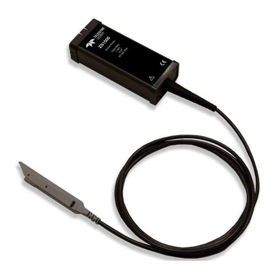
- Page 1 Operator’s Manual ZS Series High-Impedance Active Probes...
- Page 3 ZS1000, ZS1500, ZS2500 High-Impedance Active Probes Operator’s Manual April, 2017...
- Page 4 However, clients are encouraged to distribute and duplicate Teledyne LeCroy documentation for their own internal educational purposes. Teledyne LeCroy is a registered trademark of Teledyne LeCroy, Inc. Windows is a registered trademark of Microsoft Corporation. Other product or brand names are trademarks or requested trademarks of their respective holders.
- Page 5 This warranty replaces all other warranties, expressed or implied, including but not limited to any implied warranty of merchantability, fitness or adequacy for any particular purposes or use. Teledyne LeCroy shall not be liable for any special, incidental, or consequential damages, whether in contract or...
-
Page 6: Table Of Contents
Handling the Probe ................10 Connecting the Probe to the Test Circuit .......... 10 Connecting the Probe to an Oscilloscope ......... 10 Operation with a Teledyne LeCroy Oscilloscope ....... 11 Auto Zero ....................11 High Frequency Measurements ............12 Care and Maintenance ................. 16 Cleaning .................... -
Page 7: Safety Instructions
Operator’s Manual Safety Instructions Observe generally accepted safety procedures in addition to the precautions listed here. The overall safety of any system incorporating this accessory is the responsibility of the assembler of the system. Symbols These symbols appear on the probe body or in documentation to alert you to important safety considerations. -
Page 8: Introduction
With low input capacitance and high input resistance, circuit loading is minimized. The ZS probes can be used with a variety of Teledyne LeCroy oscilloscopes with MAUI firmware version 6.5.0.5 or later (see the product page at teledynelecroy.com/oscilloscope for compatibility). -
Page 9: Standard Accessories
Operator’s Manual Standard Accessories ZS Series probes are shipped with the following standard accessories: Standard Accessory Replacement Part Number Straight Pin Lead – Short PK-ZS-003 Straight Pin Lead – Long PK-ZS-004 Right Angle Lead – Short PACC-LD003 Right Angle Lead – Long... -
Page 10: Tips
ZS Series High-Impedance, Active Probes Tips Straight Tip The straight tip is rugged and designed for general probing. Fits in either probe socket. IC Lead Tip The IC Lead Tip is covered in insulation on all sides (except for a small edge). This tip was designed to prevent shorting neighboring IC leads. -
Page 11: Grounds
Operator’s Manual Grounds Offset Ground The Offset Ground is designed to be attached to either socket of the probe head. The Offset Ground connects to the ground socket and wraps around the probe head, making it possible to probe a signal and ground that are extremely close together. -
Page 12: Leads
ZS Series High-Impedance, Active Probes Leads While longer leads provide greater flexibility when connecting the probe to a circuit, the added inductance may degrade the fidelity of high frequency signals. Short and Long These leads have a socket on one end and a... -
Page 13: Probe Holder
Operator’s Manual Probe Holder Freehand Probe Holder The FreeHand lets you focus on the oscilloscope screen instead of on maintaining contact to multiple test points. It allows you to concentrate on what is really important – the waveform. It is designed to keep most of the weight on the probe tip and will prevent lost contact when a bump to the table shakes the circuit under test. -
Page 14: Probe Impedance And Equivalent Circuits
ZS Series High-Impedance, Active Probes Probe Impedance and Equivalent Circuits ZS1x00 Impedance Chart 1000000 100000 10000 1000 10Hz 100Hz 1kHz 10kHz 100kHz 1MHz 10MHz 100MHz 1000MHz 10000MHz ZS1x00 Equivalent Circuit... - Page 15 Operator’s Manual ZS2500 Impedance Chart 1000000 100000 10000 1000 100Hz 1kHz 10kHz 100kHz 1MHz 10MHz 100MHz 1000MHz 10000MHz ZS2500 Equivalent Circuit...
-
Page 16: Probe Operation
Probe Operation Handling the Probe The ZS Series probes are precision test instruments. Exercise care when handling and storing the probe. Always handle the probe by the probe body or compensation box. Avoid putting excessive strain or exposing the probe cable to sharp bends. -
Page 17: Operation With A Teledyne Lecroy Oscilloscope
Operator’s Manual Operation with a Teledyne LeCroy Oscilloscope When the ZS probe is connected to any compatible Teledyne LeCroy oscilloscope, the displayed scale factor and measurement values are automatically adjusted. A Probe dialog appears behind the corresponding Channel dialog. The probe can be controlled through the oscilloscope front panel: The Volts/Div knob controls the oscilloscope’s scale factor to give... -
Page 18: High Frequency Measurements
ZS Series High-Impedance, Active Probes High Frequency Measurements Probe Input Loading When you touch a probe to the circuit under test, the probe will affect your measurement because of the probe’s input impedance introduced into the circuit. All probes present resistive, capacitive and inductive loading. - Page 19 Operator’s Manual low and cannot be reduced, you can only try to reduce the inductance. This can be accomplished by using the shortest possible input lead as well as the shortest possible ground lead. For example, to obtain the shortest possible ground lead when measuring IC related signals, attach a small piece of copper clad material to the top of the IC package and connect this to the package grounding wires.
- Page 20 ZS Series High-Impedance, Active Probes Capacitive Loading Capacitive loading is usually the most troublesome of the three loading effects. It can affect the rise time, bandwidth and delay time measurements. At higher frequencies the capacitive loading can affect the amplitude as well as the waveshape of the measured signal by introducing an exponential response to the waveform.
- Page 21 Operator’s Manual probe source where is the probe’s input impedance and is the source impedance. For example: At 750 MHz, where the probe input impedance has reduced to 236 Ω, and a source resistance of 250 Ω the probe output amplitude is reduced to: ����...
-
Page 22: Care And Maintenance
The ZS probes utilize fine pitch surface mount devices. It is therefore impractical to attempt to repair in the field. Defective probes must be returned to a Teledyne LeCroy service facility for diagnosis and exchange. Defective probes under warranty are repaired or replaced. A probe that is not under warranty can be exchanged for a factory refurbished probe for a modest fee. -
Page 23: Performance Verification
Operator’s Manual Performance Verification This procedure can be used to verify the warranted characteristics of a ZS Series High Impedance Active Probe. It tests: Output Zero Voltage • LF Attenuation Accuracy • Performance verification can be completed without removing the probe covers or exposing the user to hazardous voltages. - Page 24 ZS Series High-Impedance, Active Probes Description Minimum Requirement Example Equipment Oscilloscope ProBus Interface; Teledyne LeCroy Windows-based WaveRunner 8000 or HDO 6000 Digital 4.5 digit Keysight 34401A Multimeter DC: 0.1% Accuracy Fluke 8842A-09 (DMM) with test AC: 0.1% Accuracy probe leads...
-
Page 25: Test Setup And Preliminary Procedure
Operator’s Manual Test Setup and Preliminary Procedure 1. Connect the probe to the female end of the ProBus Extension Cable. Connect the male end of the ProBus Extension Cable to channel 1 of the oscilloscope. 2. Turn on the oscilloscope and allow at least 20 minutes warm-up time for the probe and oscilloscope before performing the Verification Procedure. -
Page 26: Verification Procedure
ZS Series High-Impedance, Active Probes Verification Procedure A. Output Zero Voltage Output Zero Voltage Test Setup 1. Connect one end of a BNC cable to the female BNC connector on the probe end of the ProBus extender cable. Connect the precision 50 Ω... - Page 27 Operator’s Manual B. LF Attenuation Accuracy LF Attenuation Accuracy Setup 1. Disconnect the BNC tee at the power supply from the dual banana plug adapter. Connect the BNC tee to the output of the function gen erator. (Use a 50 Ω termination if the function generator requires such a load.) 2.
- Page 28 ZS Series High-Impedance, Active Probes 5. Set the DMM to read AC volt and set the range to measure 5.0 Vrms. 6. Set the mode of the function generator to sine wave, the frequency to 70 Hz and the output amplitude to 5 Vrms ±10 mV as measured on the DMM.
- Page 29 Operator’s Manual 18. Divide the reading recorded in step B-17 by 10. 19. Record the result to 100 μV resolution as "Expected Output Voltage, mid range" in the test record. 20. Remove the banana plug adapter from the DMM and connect the precision 50 Ω...
-
Page 30: Zs Series Probe Test Record
ZS Series High-Impedance, Active Probes ZS Series Probe Test Record Technician:_____________________________________________ Date:_____________________ Equipment Used Equipment Model Serial Number Cal Due Date Oscilloscope Digital Multimeter Function Generator Probe Lead Test Record UTPUT OLTAGE Step Description Results 1.0 mV Output Zero (Test limit ≤ ±... -
Page 31: Reference Material
Operator’s Manual Reference Material Certifications Teledyne LeCroy certifies compliance to the following standards as of the date of publication. For the current certifications, see the EC Declaration of Conformity shipped with your product. EMC Compliance EC D - EMC ECLARATION OF... - Page 32 ZS Series High-Impedance, Active Probes & N - EMC USTRALIA EALAND ECLARATION OF ONFORMITY The probe complies with the EMC provision of the Radio Communications Act per the following standards, in accordance with requirements imposed by the Australian Communication and Media Authority (ACMA): AS/NZS CISPR 11:2009/A1:2010, IEC 55011:2009/A1:2010 Radiated and Conducted Emissions, Group 1, Class A.
- Page 33 Operator’s Manual Returning a Product for Service Contact your regional Teledyne LeCroy service center for calibration or other service. If the product cannot be serviced on location, the service center will give you a Return Material Authorization (RMA) code and instruct you where to ship the product.
- Page 34 ZS Series High-Impedance, Active Probes Technical Support Live Support Registered users can contact their local Teledyne LeCroy service center at the number listed on our website. You can also request Technical Support via the website at: teledynelecroy.com/support/techhelp Resources Teledyne LeCroy publishes a free Technical Library on its website. Manuals, tutorials, application notes, white papers, and videos are available to help you get the most out of your Teledyne LeCroy products.
- Page 36 928327-00 Rev A April 2017...