York YCAL Series Manual
Air-cooled scroll chillers with brazed plate heat exchangers style e
Hide thumbs
Also See for YCAL Series:
- Start-up checklist (6 pages) ,
- Installation operation & maintenance (174 pages)

Related Manuals for York YCAL Series


Summary of Contents for York YCAL Series
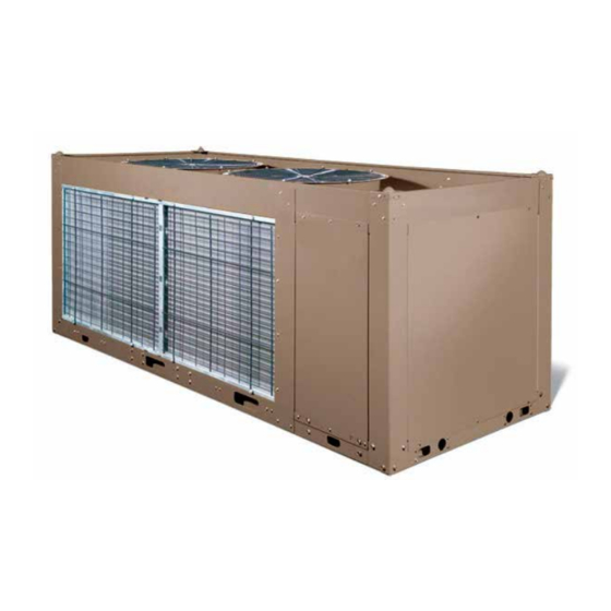
- Page 1 FORM 150.67-EG1 (219) MODEL YCAL AIR-COOLED SCROLL CHILLERS WITH BRAZED PLATE HEAT EXCHANGERS STYLE E 15 – 65 TON 53 – 218 kW 50 and 60 Hz R-410A...
- Page 2 46 = 460-3-60 58 = 575-3-60 L = SCROLL COMPRESSOR REFRIGERANT = R-410a Y = YORK CHILLER E = HIGH EFFICIENCY Approvals • ASME Boiler and Pressure Vessel Code – Section Vlll Division 1 • AHRI Standard 550/590 and 551/591 •...
-
Page 3: Table Of Contents
FORM 150.67-EG1 (219) Table Of Contents INTRODUCTION ..............................5 MICROCOMPUTER CONTROL CENTER ......................7 ACCESSORIES AND OPTIONS ........................... 10 SELECTION DATA ..............................13 DESIGN PARAMETERS ............................17 WATER PRESSURE DROP ........................... 18 RATINGS ................................20 PHYSICAL DATA AND NOMINAL RATINGS ......................38 PART LOAD RATINGS ............................ - Page 4 FORM 150.67-EG1 (219) THIS PAGE INTENTIONALLY LEFT BLANK. JOHNSON CONTROLS...
-
Page 5: Introduction
FORM 150.67-EG1 (219) Introduction YORK Air-Cooled Scroll Chillers provide chilled water for all air conditioning applications using central station air handling or terminal units. They are completely self-contained and are designed for outdoor (roof or ground level) installation. Each unit includes hermetic... - Page 6 They feature ball bearings that are double-sealed and permanently lubricated. AHRI CERTIFICATION PROGRAM YORK YCAL chillers have been tested and certified by Air-Conditioning, Heating and Re- frigeration Institute (AHRI) in accordance with the latest edition of AHRI Standard 550/590 (I-P).
-
Page 7: Microcomputer Control Center
FORM 150.67-EG1 (219) MicroComputer Control Center All controls are contained in a NEMA 3R powder painted steel cabinet with a gasketed door and include the following features: • Liquid Crystal Display (LCD) with Light Emitting Diode (LED) backlighting for outdoor viewing: •... - Page 8 FORM 150.67-EG1 (219) MicroComputer Control Center (Cont'd) • Low suction pressure cutout • High discharge pressure cutout • Anti-recycle timer (compressor start cycle time) • Anti-coincident timer (delay compressor starts) • UNIT section to set the following rules: • Set time •...
- Page 9 FORM 150.67-EG1 (219) MicroComputer Control Center (Cont'd) • Lead system definition • Compressor starts and operating hours (each compressor) • Status of hot gas valves, evaporator heater and fan operation • Run permissive status • Number of running compressors • Liquid-solenoid valve status •...
-
Page 10: Accessories And Options
FORM 150.67-EG1 (219) Accessories and Options All accessories and options are factory mounted unless otherwise noted. ELECTRICAL OPTIONS Single-Point Supply Terminal Block – Standard. Includes enclosure, terminal-block and interconnecting wiring to the compressors. Separate external protection must be sup- plied, by others, in the incoming compressor-power wiring. (Do not include this option if either the SinglePoint NonFused Disconnect Switch or Single-Point Circuit Breaker op- tions have been included.) Single-Point Non-Fused Disconnect Switch –... - Page 11 FORM 150.67-EG1 (219) Accessories and Options (Cont'd) COMPRESSOR, PIPING, EVAPORATOR OPTIONS Low Temperature Glycol – Required for glycol chilling below 30°F (-1°C) leaving glycol temperature. Option includes resized thermal expansion valve. Chicago Code Relief Valves – Unit will be provided with relief valves to meet Chicago code requirements.
- Page 12 FORM 150.67-EG1 (219) Accessories and Options (Cont'd) Copper Fin Condenser Coils – The unit coils are constructed with copper fins. (This is not recommended for units in areas where they may be exposed to acid rain.) Enclosure Panels (Unit) – Tamperproof enclosure panels prevent unauthorized access to units.
-
Page 13: Selection Data
FORM 150.67-EG1 (219) Selection Data GUIDE TO SELECTION Capacity ratings for the YCAL Packaged Air-Cooled Liquid Chillers, shown on pages 20 through 37 cover the majority of design applications for these units. For unusual appli- cations or uses beyond the scope of this catalog, please consult your nearest Johnson Controls Office or sales representative. - Page 14 0.989 26.600 1.650 METHOD OF SELECTION To select a YORK Packaged Air-Cooled Liquid Chiller, the following data must be known: 1. Design Capacity in tons refrigeration (TR). 2. Entering and Leaving Liquid Temperatures. 3. Outside ambient air temperature in °F.
- Page 15 FORM 150.67-EG1 (219) Selection Data (Cont'd) 4. Calculate Compressor kW at 50 Tons: kW = x 51.8kW =47.6kW 54.4 5. Calculate GPM: (50 Tons)x 24 GPM = =120GPM 10°F Range 6. From page 18, read 6 ft of water cooler pressure drop from GPM: 16 A YCAL0056 is suitable.
- Page 16 FORM 150.67-EG1 (219) Selection Data (Cont'd) 7. Determine average full load Compressor kW at 34 tons: 34 Tons x (41.77) =41.93 Compressor kW 33.87 Tons 8. Determine E.G. GPM: Tons x Gal °F / min/ Ton Factor GPM = RANGE 9.
-
Page 17: Design Parameters
FORM 150.67-EG1 (219) Design Parameters ENGLISH LEAVING WATER COOLER AIR ON YCAL TEMPERATURE (°F) FLOW (GPM) CONDENSER (°F) 0019EE 0022EE 0028EE 0033EE 0043EE 0046EE 0052EE 0056EE 0066EE SI UNITS LEAVING WATER COOLER AIR ON YCAL TEMPERATURE (°C) FLOW (L/S) CONDENSER (°C) 0019EE 12.8 -17.7... -
Page 18: Water Pressure Drop
FORM 150.67-EG1 (219) Water Pressure Drop YCAL EVAPORATOR PRESSURE DROP CURVE WATER FLOW RATE (GPM) LD18667 EVAPORATOR CURVE CHILLER MODEL YCAL0019EE YCAL0022EE YCAL0028EE YCAL0033EE YCAL0043EE YCAL0046EE YCAL0052EE YCAL0056EE YCAL0066EE JOHNSON CONTROLS... - Page 19 FORM 150.67-EG1 (219) Water Pressure Drop (Cont'd) YCAL EVAPORATOR PRESSURE DROP CURVE WATER FLOW RATE (l/s) LD18668 EVAPORATOR CURVE CHILLER MODEL YCAL0019EE YCAL0022EE YCAL0028EE YCAL0033EE YCAL0043EE YCAL0046EE YCAL0052EE YCAL0056EE YCAL0066EE JOHNSON CONTROLS...
-
Page 20: Ratings
FORM 150.67-EG1 (219) Ratings R-410A (60HZ) ENGLISH MODEL: YCAL0019EE IPLV = 14.6 AIR TEMPERATURE ON CONDENSER (°F) LCWT 75.0 80.0 85.0 90.0 95.0 TONS TONS TONS TONS TONS (°F) 40.0 16.2 13.6 13.3 15.8 14.4 12.3 15.3 15.3 11.3 14.9 16.3 10.3 14.4... - Page 21 FORM 150.67-EG1 (219) Ratings (Cont'd) R-410A (60HZ) ENGLISH MODEL: YCAL0019EE IPLV = 14.6 AIR TEMPERATURE ON CONDENSER (°F) LCWT 100.0 105.0 110.0 115.0 120.0 125.0 TONS KW EER TONS KW EER TONS KW EER TONS KW EER TONS KW EER TONS KW (°F) 40.0 14.0...
- Page 22 FORM 150.67-EG1 (219) Ratings (Cont'd) R-410A (60HZ) ENGLISH MODEL: YCAL0033EE IPLV = 14.5 AIR TEMPERATURE ON CONDENSER (°F) LCWT 75.0 80.0 85.0 90.0 95.0 TONS TONS TONS TONS TONS (°F) 29.7 23.8 13.3 29.0 25.0 12.4 28.3 26.3 11.6 27.5 27.7 10.8 26.7...
- Page 23 FORM 150.67-EG1 (219) Ratings (Cont'd) R-410A (60HZ) ENGLISH MODEL: YCAL0033EE IPLV= 14.5 AIR TEMPERATURE ON CONDENSER (°F) LCWT 100.0 105.0 110.0 115.0 120.0 125.0 TONS KW EER TONS KW EER TONS KW EER TONS KW EER TONS KW EER TONS KW (°F) 40.0 25.9...
- Page 24 FORM 150.67-EG1 (219) Ratings (Cont'd) R-410A (60HZ) ENGLISH MODEL: YCAL0052EE IPLV = 15.1 AIR TEMPERATURE ON CONDENSER (°F) LCWT 75.0 80.0 85.0 90.0 95.0 TONS TONS TONS TONS TONS (°F) 40.0 47.7 38.0 12.8 46.6 40.1 12.0 45.5 42.3 11.1 44.3 44.7 10.3...
- Page 25 FORM 150.67-EG1 (219) Ratings (Cont'd) R-410A (60HZ) ENGLISH MODEL: YCAL0052EE IPLV= 15.1 AIR TEMPERATURE ON CONDENSER (°F) LCWT 100.0 105.0 110.0 115.0 120.0 125.0 TONS KW EER TONS KW EER TONS KW EER TONS KW EER TONS KW EER TONS KW (°F) 40.0 41.9 49.9...
- Page 26 FORM 150.67-EG1 (219) Ratings (Cont'd) R-410A (60HZ) SI MODEL: YCAL0019EE AIR TEMPERATURE ON CONDENSER (°C) LCWT 25.0 30.0 35.0 40.0 45.0 50.0 (°C) 57.3 14.0 54.6 15.6 51.7 17.4 48.6 19.4 45.2 21.7 23.2 10.5 59.0 14.1 56.2 15.7 53.2 17.5 50.1 19.5...
- Page 27 FORM 150.67-EG1 (219) Ratings (Cont'd) R-410A (60HZ) SI MODEL: YCAL0033EE AIR TEMPERATURE ON CONDENSER (°C) LCWT 25.0 30.0 35.0 40.0 45.0 50.0 (°C) 105.1 24.3 100.6 26.6 95.6 29.3 90.1 32.2 84.2 35.6 42.7 17.7 108.3 24.6 103.6 26.9 98.5 29.5 92.9 32.5...
- Page 28 FORM 150.67-EG1 (219) Ratings (Cont'd) R-410A (60HZ) SI MODEL: YCAL0052EE AIR TEMPERATURE ON CONDENSER (°C) LCWT 25.0 30.0 35.0 40.0 45.0 50.0 (°C) 169.2 39.0 162.0 42.9 154.3 47.4 146.0 52.4 136.9 57.9 126.8 64.1 174.6 39.3 167.2 43.2 159.2 47.7 150.7 52.7 141.3 58.2 131.0 64.4...
- Page 29 FORM 150.67-EG1 (219) Ratings (Cont'd) R-410A (50HZ) ENGLISH MODEL: YCAL0019EE IPLV = 15.5 AIR TEMPERATURE ON CONDENSER (°F) LCWT 75.0 80.0 85.0 90.0 95.0 TONS TONS TONS TONS TONS (°F) 40.0 13.7 11.0 14.2 13.3 11.6 13.1 12.9 12.3 12.0 12.5 13.1 11.0...
- Page 30 FORM 150.67-EG1 (219) Ratings (Cont'd) R-410A (50HZ) ENGLISH MODEL: YCAL0019EE IPLV = 15.5 AIR TEMPERATURE ON CONDENSER (°F) LCWT 100.0 105.0 110.0 115.0 120.0 125.0 TONS KW EER TONS KW EER TONS KW EER TONS KW EER TONS KW EER TONS KW (°F) 40.0 11.7...
- Page 31 FORM 150.67-EG1 (219) Ratings (Cont'd) R-410A (50HZ) ENGLISH MODEL: YCAL0033EE IPLV = 15.9 AIR TEMPERATURE ON CONDENSER (°F) LCWT 75.0 80.0 85.0 90.0 95.0 TONS TONS TONS TONS TONS (°F) 40.0 24.8 18.8 14.5 24.3 19.9 13.5 23.7 21.0 12.5 23.1 22.3 11.5...
- Page 32 FORM 150.67-EG1 (219) Ratings (Cont'd) R-410A (50HZ) ENGLISH MODEL: YCAL0033EE IPLV = 15.9 AIR TEMPERATURE ON CONDENSER (°F) LCWT 100.0 105.0 110.0 115.0 120.0 125.0 TONS KW EER TONS KW EER TONS KW EER TONS KW EER TONS KW EER TONS KW (°F) 40.0 21.7...
- Page 33 FORM 150.67-EG1 (219) Ratings (Cont'd) R-410A (50HZ) ENGLISH MODEL: YCAL0052EE IPLV = 16.2 AIR TEMPERATURE ON CONDENSER (°F) LCWT 75.0 80.0 85.0 90.0 95.0 TONS TONS TONS TONS TONS (°F) 40.0 39.7 29.8 14.1 38.9 31.6 13.2 38.0 33.5 12.2 37.0 35.5 11.3...
- Page 34 FORM 150.67-EG1 (219) Ratings (Cont'd) R-410A (50HZ) ENGLISH MODEL: YCAL0052EE IPLV = 16.2 AIR TEMPERATURE ON CONDENSER (°F) LCWT 100.0 105.0 110.0 115.0 120.0 125.0 TONS KW EER TONS KW EER TONS KW EER TONS KW EER TONS KW EER TONS KW (°F) 40.0 35.0...
- Page 35 FORM 150.67-EG1 (219) Ratings (Cont'd) R-410A (50HZ) SI MODEL: YCAL0019EE AIR TEMPERATURE ON CONDENSER (°C) LCWT 25.0 30.0 35.0 40.0 45.0 50.0 (°C) 48.3 11.3 45.9 12.5 43.4 14.0 40.6 15.7 37.7 17.6 19.2 49.8 11.4 47.3 12.6 44.7 14.1 41.9 15.8 39.0...
- Page 36 FORM 150.67-EG1 (219) Ratings (Cont'd) R-410A (50HZ) SI MODEL: YCAL0033EE AIR TEMPERATURE ON CONDENSER (°C) LCWT 25.0 30.0 35.0 40.0 45.0 50.0 (°C) 88.1 19.3 84.3 21.4 80.2 23.8 75.8 26.5 71.0 29.4 65.9 32.7 90.7 19.4 86.9 21.5 82.7 23.9 78.1 26.6...
- Page 37 FORM 150.67-EG1 (219) Ratings (Cont'd) R-410A (50HZ) SI MODEL: YCAL0052EE AIR TEMPERATURE ON CONDENSER (°C) LCWT 25.0 30.0 35.0 40.0 45.0 50.0 (°C) 140.8 30.6 135.2 33.9 129.0 37.8 122.2 42.1 114.7 47.0 106.5 52.3 145.2 30.8 139.5 34.1 133.2 38.0 126.1 42.3 118.5 47.2 110.2 52.5...
-
Page 38: Physical Data And Nominal Ratings
FORM 150.67-EG1 (219) Physical Data and Nominal Ratings 60HZ MODEL YCAL00 Length, in 109.8 109.8 109.8 109.8 144.8 144.8 144.8 144.8 153.6 Width, in 44.7 44.7 44.7 44.7 90.6 90.6 90.6 90.6 90.6 Height, in 46.1 46.1 47.8 47.8 62.6 62.6 62.6 NOMINAL RATINGS... - Page 39 FORM 150.67-EG1 (219) Physical Data and Nominal Ratings (Cont'd) 50HZ MODEL YCAL00 Length, mm 2789 2789 2789 2789 3678 3678 3678 3678 3901 Width, mm 1135 1135 1135 1135 2301 2301 2301 2301 2301 Height, mm 1171 1171 1270 1270 1214 1214 1590...
-
Page 40: Part Load Ratings
FORM 150.67-EG1 (219) Part Load Ratings 60 HZ YCAL0019 YCAL0046 AMBENT UNIT AMBIENT UNIT % DISPL. TONS % DISPL. TONS (°F) (°F) 15.4 17.6 95.0 10.0 39.4 41.0 95.0 10.2 70.2 16.0 31.5 25.2 82.9 12.3 IPLV=14.6 22.4 14.9 69.1 15.2 11.6 55.0... - Page 41 FORM 150.67-EG1 (219) Part Load Ratings (Cont'd) 50 HZ YCAL0019 YCAL0046 AMBIENT AMBIENT UNIT UNIT % DISPL. TONS % DISPL. TONS (°F) (°F) 13.0 14.2 95.0 10.6 32.9 33.3 95.0 10.8 70.2 17.0 26.2 20.1 82.8 13.5 IPLV=15.5 18.6 11.5 68.9 17.0 55.0...
-
Page 42: Unit Dimensions
FORM 150.67-EG1 (219) Unit Dimensions YCAL0019 3 1/4" 6 3/4" 7/8" TYP. 3 15/16" VIEW B-B BOTTOM OF PANEL 2" DIA (2) 3.0 X 1.50 46 1/16" RIGGING HOLES 45 1/4" BOTH ENDS 2 1/4" 11 5/8" TO ACCESS PANEL 16 1/4" 11"... - Page 43 FORM 150.67-EG1 (219) Unit Dimensions (Cont'd) YCAL0019 9/16" DIA MOUNTING HOLES(typ) 1 1/16" CONTROL COMPR PANEL 44 3/8" END CAP WIDTH 32 1/8" 6 1/8" 1 1/16" ORIGIN 2 1/4" 5" TOP VIEW 17" 1" 9 1/16" CONTROL PANEL 38 3/16" 3 3/8"...
- Page 44 FORM 150.67-EG1 (219) Unit Dimensions (Cont'd) YCAL0022 3 1/4" 6 3/4" 7/8" TYP. 3 15/16" VIEW B-B BOTTOM OF PANEL 2" DIA (2) 3.0 X 1.50 46 1/16" RIGGING HOLES 45 1/4" BOTH ENDS 2 1/4" 11 5/8" TO ACCESS PANEL 16 1/4" 11"...
- Page 45 FORM 150.67-EG1 (219) Unit Dimensions (Cont'd) YCAL0022 9/16" DIA MOUNTING HOLES(typ) 1 1/16" CONTROL COMPR PANEL 44 3/8" END CAP WIDTH 32 1/8" 6 1/8" 1 1/16" ORIGIN 2 1/4" 5" TOP VIEW 17" 1" 9 1/16" CONTROL PANEL 38 3/16" 3 3/8"...
- Page 46 FORM 150.67-EG1 (219) Unit Dimensions (Cont'd) YCAL0028 LD18673 NOTE: Placement on a level surface of free of obstructions (including snow, for winter operation) or air circulation ensures rated performance, reli- able operation, and ease of maintenance. Site restrictions may compromise minimum clearances indicated below, resulting in unpredictable airflow patterns and possible diminished performance.
- Page 47 FORM 150.67-EG1 (219) Unit Dimensions (Cont'd) YCAL0028 LD18674 JOHNSON CONTROLS...
- Page 48 FORM 150.67-EG1 (219) Unit Dimensions (Cont'd) YCAL0033 3 1/4" 6 3/4" 7/8" TYP. 3 15/16" VIEW B-B BOTTOM OF PANEL 2" DIA (2) 3.0 X 1.50 50 1/16" RIGGING HOLES 49 1/4" BOTH ENDS 8 1/2" 2 1/4" 15 1/2" TO ACCESS PANEL 13 3/8"...
- Page 49 FORM 150.67-EG1 (219) Unit Dimensions (Cont'd) YCAL0033 9/16" DIA MOUNTING HOLES(typ) 1 1/16" CONTROL COMPR PANEL 44 3/8" END CAP WIDTH 32 1/8" 6 1/8" 1 1/16" 1 7/8" ORIGIN 5" 17" TOP VIEW 1" 9" CONTROL PANEL 42 1/8" 3 3/8"...
- Page 50 FORM 150.67-EG1 (219) Unit Dimensions (Cont'd) YCAL0043 6 3/4" 3 1/4" 7/8" TYP. 3 15/16" VIEW B-B BOTTOM OF PANEL LIQUID IN ELECTRICAL ACCESS 47 3/4" PANEL 46 15/16" 25 1/4" 9 7/8" 15 3/4" 3" ANSI/AWWA LIQUID OUT C-606 (typ) 12 5/8"...
- Page 51 FORM 150.67-EG1 (219) Unit Dimensions (Cont'd) YCAL0043 9/16" DIA MOUNTING HOLES(typ) 1 1/16" COIL COOLER 90 9/16" END CAP WIDTH 45 1/8" 1 1/16" 9 13/16" 9 13/16" ORIGIN TOP VIEW 16 3/4" 5 5/16" 38" CONTROL PANEL 25 3/8" 13 5/8"...
- Page 52 FORM 150.67-EG1 (219) Unit Dimensions (Cont'd) YCAL0046 6 3/4" 3 1/4" 7/8" TYP. 3 15/16" VIEW B-B BOTTOM OF PANEL LIQUID IN ELECTRICAL ACCESS 47 3/4" PANEL 46 15/16" 25 1/4" 9 7/8" 15 3/4" 3" ANSI/AWWA LIQUID OUT 12 5/8" C-606 (typ) 45 1/8"...
- Page 53 FORM 150.67-EG1 (219) Unit Dimensions (Cont'd) YCAL0046 9/16" DIA MOUNTING HOLES(typ) 1 1/16" COIL COOLER 90 9/16" END CAP WIDTH 45 1/8" 1 1/16" 9 13/16" 9 13/16" ORIGIN 16 3/4" TOP VIEW 5 5/16" 38" CONTROL PANEL 25 3/8" 13 5/8"...
- Page 54 FORM 150.67-EG1 (219) Unit Dimensions (Cont'd) YCAL0052 62 5/8” 61 7/8” 25 3/16” 9 7/8” LD18681 NOTE: Placement on a level surface of free of obstructions (including snow, for winter operation) or air circulation ensures rated performance, reli- able operation, and ease of maintenance. Site restrictions may compromise minimum clearances indicated below, resulting in unpredictable airflow patterns and possible diminished performance.
- Page 55 FORM 150.67-EG1 (219) Unit Dimensions (Cont'd) YCAL0052 45 1/8” 18 1/2” LD18682 JOHNSON CONTROLS...
- Page 56 FORM 150.67-EG1 (219) Unit Dimensions (Cont'd) YCAL0056 25 1/4” 9 7/8” LD18683 NOTE: Placement on a level surface of free of obstructions (including snow, for winter operation) or air circulation ensures rated performance, reli- able operation, and ease of maintenance. Site restrictions may compromise minimum clearances indicated below, resulting in unpredictable airflow patterns and possible diminished performance.
- Page 57 FORM 150.67-EG1 (219) Unit Dimensions (Cont'd) YCAL0056 45 1/8” 16 3/4” LD18684 JOHNSON CONTROLS...
- Page 58 FORM 150.67-EG1 (219) Unit Dimensions (Cont'd) YCAL0066 6 3/4" 3 1/4" 7/8" TYP. VIEW B-B 3 15/16" BOTTOM OF PANEL LIQUID IN 62 5/8" 61 7/8" ELECTRICAL ACCESS PANEL 25 1/16" 9 3/4" 15 3/4" 3" ANSI/AWWA C-606 LIQUID OUT (typ) 12 5/8"...
- Page 59 FORM 150.67-EG1 (219) Unit Dimensions (Cont'd) YCAL0066 9/16" DIA MOUNTING HOLES(typ) 1 1/16" COIL COOLER 90 9/16" END CAP WIDTH 43 1/8" 1 1/16" ORIGIN 9 13/16" 9 13/16" TOP VIEW 12 3/4" 5 3/16" 38" CONTROL PANEL 25 3/8" 28 9/16"...
- Page 60 Site restrictions may compromise minimum clearances indicated below, resulting in unpredictable airflow patterns and possible diminished performance. YORK's unit controls will optimize operation without nuisance high-pressure safety cutouts; however, the system designer must consider potential performance degradation. Recommended minimum clearances: front to wall - 2m;...
- Page 61 FORM 150.67-EG1 (219) Unit Dimensions (Cont'd) YCAL0019 SI 14 DIA MOUNTING HOLES(typ) CONTROL COMPR PANEL 1128 END CAP WIDTH ORIGIN TOP VIEW CONTROL PANEL (2) 178 X 57 FORKLIFT HOLES (2) 76 X 38 BOTH SIDES RIGGING HOLES BOTH SIDES 1130 1892 2466...
- Page 62 Site restrictions may compromise minimum clearances indicated below, resulting in unpredictable airflow patterns and possible diminished performance. YORK's unit controls will optimize operation without nuisance high-pressure safety cutouts; however, the system designer must consider potential performance degradation. Recommended minimum clearances: front to wall - 2m;...
- Page 63 FORM 150.67-EG1 (219) Unit Dimensions (Cont'd) YCAL0022 SI LD18692 JOHNSON CONTROLS...
- Page 64 Site restrictions may compromise minimum clearances indicated below, resulting in unpredictable airflow patterns and possible diminished performance. YORK's unit controls will optimize operation without nuisance high-pressure safety cutouts; however, the system designer must consider potential performance degradation. Recommended minimum clearances: front to wall - 2m;...
- Page 65 FORM 150.67-EG1 (219) Unit Dimensions (Cont'd) YCAL0028 SI 16 DIA MOUNTING HOLES(TYP) COMPR 1128 END CAP WIDTH ORIGIN TOP VIEW CONTROL PANEL 1070 (2) 178 X 57 FORKLIFT HOLES (2) 76 X 38 BOTH SIDES RIGGING HOLES 1282 BOTH SIDES 2044 2669 3005...
- Page 66 Site restrictions may compromise minimum clearances indicated below, resulting in unpredictable airflow patterns and possible diminished performance. YORK's unit controls will optimize operation without nuisance high-pressure safety cutouts; however, the system designer must consider potential performance degradation. Recommended minimum clearances: front to wall - 2m;...
- Page 67 FORM 150.67-EG1 (219) Unit Dimensions (Cont'd) YCAL0033 SI 14 DIA MOUNTING HOLES(typ) CONTROL COMPR PANEL 1128 END CAP WIDTH ORIGIN TOP VIEW CONTROL 1070 (2) 178 X 57 FORKLIFT HOLES BOTH SIDES (2) 76 X 38 RIGGING HOLES 1282 BOTH SIDES 2044 2669 3005...
- Page 68 Site restrictions may compromise minimum clearances indicated below, resulting in unpredictable airflow patterns and possible diminished performance. YORK's unit controls will optimize operation without nuisance high-pressure safety cutouts; however, the system designer must consider potential performance degradation. Recommended minimum clearances: front to wall - 2m;...
- Page 69 FORM 150.67-EG1 (219) Unit Dimensions (Cont'd) YCAL0043 SI 14 DIA MOUNTING HOLES(typ) COIL COOLER 2301 END CAP WIDTH 1146 ORIGIN TOP VIEW CONTROL PANEL TWO LIFTING HOLES BOTH SIDES 3678 LD18698 FRONT VIEW JOHNSON CONTROLS...
- Page 70 Site restrictions may compromise minimum clearances indicated below, resulting in unpredictable airflow patterns and possible diminished performance. YORK's unit controls will optimize operation without nuisance high-pressure safety cutouts; however, the system designer must consider potential performance degradation. Recommended minimum clearances: front to wall - 2m;...
- Page 71 FORM 150.67-EG1 (219) Unit Dimensions (Cont'd) YCAL0046 SI 14 DIA MOUNTING HOLES(typ) COIL COOLER 2301 END CAP WIDTH 1146 ORIGIN TOP VIEW CONTROL PANEL TWO LIFTING HOLES BOTH SIDES 3678 LD18700 FRONT VIEW JOHNSON CONTROLS...
- Page 72 Site restrictions may compromise minimum clearances indicated below, resulting in unpredictable airflow patterns and possible diminished performance. YORK's unit controls will optimize operation without nuisance high-pressure safety cutouts; however, the system designer must consider potential performance degradation. Recommended minimum clearances: front to wall - 2m;...
- Page 73 FORM 150.67-EG1 (219) Unit Dimensions (Cont'd) YCAL0052 SI LD18702 JOHNSON CONTROLS...
- Page 74 Site restrictions may compromise minimum clearances indicated below, resulting in unpredictable airflow patterns and possible diminished performance. YORK's unit controls will optimize operation without nuisance high-pressure safety cutouts; however, the system designer must consider potential performance degradation. Recommended minimum clearances: front to wall - 2m;...
- Page 75 FORM 150.67-EG1 (219) Unit Dimensions (Cont'd) YCAL0055 SI 14 DIA MOUNTING HOLES(typ) COIL COOLER 2301 END CAP WIDTH 1146 ORIGIN TOP VIEW CONTROL PANEL TWO LIFTING HOLES BOTH SIDES 3678 LD18704 FRONT VIEW JOHNSON CONTROLS...
- Page 76 Site restrictions may compromise minimum clearances indicated below, resulting in unpredictable airflow patterns and possible diminished performance. YORK's unit controls will optimize operation without nuisance high-pressure safety cutouts; however, the system designer must consider potential performance degradation. Recommended minimum clearances: front to wall - 2m;...
- Page 77 FORM 150.67-EG1 (219) Unit Dimensions (Cont'd) YCAL0052 14 DIA MOUNTING HOLES(typ) COIL COOLER 2301 END CAP WIDTH 1095 ORIGIN TOP VIEW CONTROL PANEL TWO LIFTING HOLES BOTH SIDES 3902 LD18706 FRONT VIEW JOHNSON CONTROLS...
-
Page 78: Isolator Details
FORM 150.67-EG1 (219) Isolator Details TWO INCH DEFLECTION, SPRING ISOLATOR Y2RS-X 1-1/8” 5/8” 2-3/4” 2-3/4” 3/8” GAP 3/4” TYP. (4) 3/4” 7/8” STOP & 8-3/8” OPER. HEIGHT LD18443 MODEL Y2RSI-2D SEISMICALLY RESTRAINED VIBRATION ISOLATOR FOR 2" DEFLECTION RATED ALLOWABLE RATED LOAD SEISMIC MOUNT SPRING RATE SOLID LOAD... - Page 79 FORM 150.67-EG1 (219) Isolator Details (Cont'd) ONE INCH DEFLECTION SPRING ISOLATOR CPX-X LD18442 DIMENSION DATA (INCHES) MOUNT TYPE 7–3/4 6–1/2 4–3/4 5–5/8 10–1/2 9–1/4 7–3/4 9/16 MODEL DEFLECTION RATED CAPACITY COLOR CODE (LBS.) NUMBER RATED (IN) CP1-1D-85 1.360 LT. PURPLE CP1-1D-120 1.200 DK.
- Page 80 FORM 150.67-EG1 (219) Isolator Details (Cont'd) ELASTOMERIC ISOLATOR RD-X MOLDED DURULENE MOLDED DURULENE Ø = AD Thru Typ 2 Places R = 0.280 Slot Typ 2 Places LD17304 MOUNT DIMENSION DATA (INCHES) TYPE RD1-WR 3.13 1.75 1.25 2.38 0.34 0.19 5/16-18 UNC X 3/4 1.25 RD2-WR...
- Page 81 FORM 150.67-EG1 (219) Isolator Details (Cont'd) ELASTOMERIC ISOLATOR RD-X RATED CAPACITY RATED DEFLECTION MODEL NUMBER DURO (± 5) [LBS] [IN] RD3-BROWN-WR RD3-BRICK RED-WR RD3-LIME-WR RD3-CHARCOAL-WR 1100 RATED CAPACITY RATED DEFLECTION MODEL NUMBER DURO (± 5) [LBS] [IN] RD4-BROWN-WR 1500 RD4-BRICK RED-WR 2250 RD4-LIME-WR 3000...
-
Page 82: Electrical Data - 50 & 60Hz
FORM 150.67-EG1 (219) Electrical Data - 50 and 60Hz YCAL0019 - YCAL0066 WIRING WITHOUT PUMP SYSTEM # 1 SYSTEM # 2 DUAL COMPR 1 COMPR 2 COMPR 1 COMPR 2 MODEL CKT. DUAL VOLT HZ DISC ELEM YCAL AMPS ELEM FUSE RLA LRA RLA LRA QTY FLA LRA RLA LRA RLA LRA QTY FLA LRA FUSE... - Page 83 FORM 150.67-EG1 (219) Electrical Data - 50 and 60Hz (Cont'd) YCAL0019 - YCAL0066 WIRING WITHOUT PUMP SYSTEM # 1 SYSTEM # 2 DUAL COMPR 1 COMPR 2 COMPR 1 COMPR 2 MODEL DUAL VOLT HZ DISC ELEM YCAL AMPS ELEM FUSE RLA LRA RLA LRA QTY FLA LRA RLA LRA RLA LRA QTY FLA LRA FUSE...
- Page 84 FORM 150.67-EG1 (219) Electrical Data - 50 & 60Hz (Cont'd) LUG RANGE FIELD WIRING LUGS FIELD WIRING LUGS FIELD WIRING LUGS TERMINAL BLOCK (STD) NF DISC. SWITCH (OPT) CIRCUIT BREAKER (OPT) YCAL HZ VOLT LUGS/ LUGS/ LUGS/ LUG WIRE RANGE LUG WIRE RANGE LUG WIRE RANGE PHASE...
-
Page 85: Electrical Notes
FORM 150.67-EG1 (219) Electrical Notes OVER CURRENT CONTROL PROTECTION, UNIT VOLTAGE POWER NF DISC SW SEE NOTE B NOTE A UNIT VOLTAGE MODELS W/O 115-1-60/50 CONTROL 30 A / 240V TRANS 200-1-60 30 A / 240V 230-1-60 30 A / 240V MODELS W/ 380-1-60 30 A / 480V... - Page 86 FORM 150.67-EG1 (219) Electrical Notes (Cont'd) NOTES: 1. Minimum Circuit Ampacity (MCA) is based on 125% of the rated load amps for the largest motor plus 100% of the rated load amps for all other loads included in the cir- cuit, per N.E.C.
-
Page 87: Circuit Breaker Calculations
FORM 150.67-EG1 (219) Circuit Breaker Calculations Max Dual Elem Fuse Max CB (MOP) = 2.25 x Current of largest motor + ∑ (remaining FLAs or RLAs) For this name plate the formula below was used: = 2.25 * RLACpr1 + RLACpr2 + RLACpr3 + Qty* RLAFans + 0.49 + FLAPump This formula will calculate the ACTUAL MOP but a table is referenced to provide the appropriate MOP. -
Page 88: Power Wiring - Single Circuit
FORM 150.67-EG1 (219) Power Wiring - Single Circuit ld18707 JOHNSON CONTROLS... - Page 89 FORM 150.67-EG1 (219) Power Wiring - Single Circuit (Cont'd) LD18744 JOHNSON CONTROLS...
- Page 90 FORM 150.67-EG1 (219) Power Wiring - Single Circuit (Cont'd) LD18745 JOHNSON CONTROLS...
-
Page 91: Power Wiring - Dual Circuit
FORM 150.67-EG1 (219) Power Wiring - Dual Circuit LD18746 JOHNSON CONTROLS... -
Page 92: Control Wiring
FORM 150.67-EG1 (219) Control Wiring FLOW SW REMOTE START/STOP PWM INPUT LOAD LIMIT INPUT CTB1 LD18747 * Factory wired with optional transformer. LD03611 JOHNSON CONTROLS... -
Page 93: Application Data
FORM 150.67-EG1 (219) Application Data UNIT LOCATION The YCAL chillers are designed for outdoor installation. When selecting a site for installa- tion, be guided by the following conditions: 1. For outdoor locations of the unit, select a place having an adequate supply of fresh air for the condenser. - Page 94 FORM 150.67-EG1 (219) Application Data (Cont'd) Mounting holes (11/16” diameter) are provided in the steel channel for bolting the unit to its foundation. See Unit Dimensions on page 42. For ground level installations, precautions should be taken to protect the unit from tam- pering by or injury to unauthorized persons.
- Page 95 FORM 150.67-EG1 (219) Application Data (Cont'd) TYPICAL PIPING FOR BRAZED-PLATE COOLERS NOTES: 1. Placement on a level surface free of obstructions (including snow, for winter operation) or air recirculation ensures rated performance, reliable operation and ease of maintenance. 2. Piping and wiring shown is for reference use only and is not in accordance with any national or local standards.
-
Page 96: Guide Specifications
FORM 150.67-EG1 (219) Guide Specifications PART 1 – GENERAL 1.01 SCOPE A. The requirements of the General Conditions, Supplementary Conditions, Division 1, and Drawings apply to all Work herein. B. Provide Microprocessor controlled, multiple-scroll compressor, air-cooled, liquid chill- ers of the scheduled capacities as shown and indicated on the Drawings, including but not limited to: 1. - Page 97 FORM 150.67-EG1 (219) Guide Specifications (Cont'd) 1.03 DELIVERY AND HANDLING G. Unit shall be delivered to job site fully assembled, and charged with refrigerant and oil by the Manufacturer. (Contractor is responsible for providing and installing the refriger- ant charge including the charge required for the field installed interconnecting piping. Chiller components shall ship with a dry nitrogen holding charge –...
- Page 98 FORM 150.67-EG1 (219) Guide Specifications (Cont'd) 2.03 REFRIGERANT CIRCUIT COMPONENTS Each refrigerant circuit shall include liquid line shutoff valve with charging port, low side pressure relief device, filter-drier, solenoid valve, sight glass with moisture indicator, ex- pansion valves, and flexible, closed-cell foam insulated suction line. Unit also includes service isolation valves as standard.
- Page 99 FORM 150.67-EG1 (219) Guide Specifications (Cont'd) 2. Remote water temperature reset via a Pulse Width Modulated (PWM) input signal or up to two steps of demand (load) limiting. 3. Software stored in non-volatile memory, with programmed setpoints retained in lith- ium battery backed real time clock (RTC) memory for minimum 5 years.
- Page 100 FORM 150.67-EG1 (219) Guide Specifications (Cont'd) 2.06 POWER CONNECTION AND DISTRIBUTION I. Power Panels: 1. NEMA 3R, powder painted steel cabinets with a gasketed protective cover. Provide main power connection(s), control power connections, compressor and fan motor start contactors, current overloads, and factory wiring. 2.
- Page 101 FORM 150.67-EG1 (219) Guide Specifications (Cont'd) P. Power Factor Correction Capacitors: Provided to correct unit compressor factors to a 0.90-0.95. Q. Condenser Coil Environmental Protection: 1. Pre-Coated: Epoxy coated aluminum fin stock to guard from corrosive agents and insulate against galvanic potential. For mild seashore or industrial locations. 2.
- Page 102 FORM 150.67-EG1 (219) Guide Specifications (Cont'd) W. Remote Cooler: Manufacturer shall provide separately: chiller less evaporator, leaving and return water sensors, and liquid line components (solenoid valves, filter driers, sight glasses, and TXVs), as discrete elements of a complete factory system. Contrac- tor shall be field erect system and provide interconnecting refrigerant piping and wiring in accordance with Manufacturer recommendations, and project plans and schedules.
- Page 103 FORM 150.67-EG1 (219) Guide Specifications (Cont'd) PART 3 - EXECUTION 3.01 INSTALLATION A. General: Rig and Install in full accordance with Manufacturers requirements, Project drawings, and Contract documents. B. Location: Locate chiller as indicated on drawings, including cleaning and service main- tenance clearance per Manufacturer instructions.
- Page 104 Printed on recycled paper Form 150.67-EG1 (219) Supersedes: 150.67-EG1 (119) © 2019 Johnson Controls, Inc. P.O. Box 423, Milwaukee, WI 53201 Printed in USA www.johnsoncontrols.com Issued on 02/08/2019...