Table of Contents
Advertisement
Quick Links
Advertisement
Table of Contents

Related Manuals for Teledyne Lecroy MS-500


Summary of Contents for Teledyne Lecroy MS-500
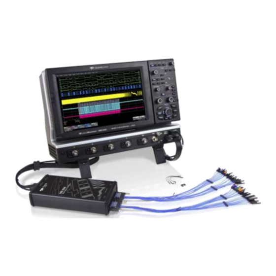
- Page 1 Operator’s Manual MS-500 Mixed Signal Oscilloscope Option...
- Page 3 MS-500 Mixed-Signal Oscilloscope Option Operator’s Manual January 2013...
- Page 4 Teledyne LeCroy shall not be responsible for any defect, damage, or failure caused by any of the following: a) attempted repairs or installations by personnel other than Teledyne LeCroy representatives or b) improper connection to incompatible equipment, or c) for any damage or malfunction caused by the use of non-Teledyne LeCroy supplies.
-
Page 5: Table Of Contents
Threshold Levels ..............16 Minimum Voltage Swing ............16 Accessing the MS-500 Toolset ..........17 Oscilloscope Analog Trigger and MS-500 Digital Trigger ..18 Digital Trace Groups ..............19 Digital Logic Threshold Setup ..........22 Digital Trigger Setup ..............24 Logic Bus Trigger Setup ............ - Page 6 MS-500 Mixed Signal Oscilloscope Option Characterize Digital or Mixed Signal ........28 System Performance Overview ..........28 Using Cursors................28 Using Measurement Parameters ........... 29 Measurement Gating ............. 30 Using Statistics and Graphing ..........30 Isolate and Analyze Signal Activity .......... 31 Zooming Waveforms ..............
-
Page 7: Welcome
The MS-500 and MS-500-36 are identical except the MS-500-36 standard configuration is for 36 channels. The MS-500-36 can be operated in 36 or 18 channel mode for higher performance. The MS-500 is configured as an 18 channel instrument and can be upgraded with an additional lead set to support 36 channels. -
Page 8: Safety Instructions
MS-500 Mixed Signal Oscilloscope Option Safety Instructions This section contains instructions that must be observed to keep the instrument operating in a correct and safe condition. You are required to follow generally accepted safety procedures in addition to the precautions specified in this section. -
Page 9: Operating Environment
Returning a Product for Service or Repair If you suspect that you have a problem with the MS-500, you should first contact your local Teledyne LeCroy service center so that they can ascertain whether this component is defective. -
Page 10: Technical Support
MS-500 Mixed Signal Oscilloscope Option Technical Support You can get assistance with installation and operation from your customer service center. Visit the Teledyne LeCroy Web site at teledynelecroy.com for the center nearest you. Staying Up-to-Date Your MS-500 hardware does not need periodic calibration. -
Page 11: Standard Equipment
Qty. 1 16” (40.64 cm) Digital Lead Set – Interfaces the MS-500 to the device under test. The lead set terminates in a 25 mil pin socket. Micro-gripper probes of various sizes are available as accessories from Teledyne LeCroy, and may be connected to the lead set. - Page 12 Qty. 20 Ground Extender – Connect to ground port of any digital input and make a simple signal and ground connection to a 0.1” square pin header. (Qty. 40 with MS-500-36 Qty. 1 Carrying Case 922245-00 Rev A...
-
Page 13: The Ms-500 Software
This might be convenient to have if you have more than one device under test and do not wish to disconnect/reconnect your cables to use the MS-500 on different DUTs. Adding this to the MS-500 enables 36 channels. Inputs are labeled D18 – D35... - Page 14 MS-500 Mixed Signal Oscilloscope Option PK400-1 – Large gripper probe set for 0.10 inch (2.54 mm) pin pitch. Includes 10 probes with color-coded leads. PK400-2 – Medium gripper probe set for 0.04 inch (1.0 mm) pin pitch. Includes 10 probes with color-coded leads.
- Page 15 Operator’s Manual PK400-3 – Small gripper probe set for 0.008 inch (0.2 mm) pin pitch. Includes 10 probes with color-coded leads. MSO-MICTOR – Mictor Connection cable, 16” (40.64 cm), 36 channel connector. MSO-3M - Interconnect cable, 16” (40.64 cm) mates with 3M connectors, 2520-6002 and 25205002..
-
Page 16: Description Of Operation
100 mV. The indeterminate range of 50 mV around the threshold voltage level is the level below which the MS-500 will not operate. However, the MS-500 can support a signal as low as 100 mV only if the input signal’s quality is adequate. -
Page 17: Getting Started With The Ms-500
Getting Started with the MS-500 Overview The MS-500 is a complete system that interfaces with the oscilloscope in a number of ways that make it easier to do the following: Set analog, digital and combination triggers. -
Page 18: Connecting Ms-500 To The Oscilloscope
2. Connect the USB 2.0 cable (attached to the Teledyne LeCroy Bus cable) to any of the side mounted USB ports on the oscilloscope. 3. Connect the other end of the Teledyne LeCroy Bus cable to the MS- 500 and fasten the thumb screws. - Page 19 Operator’s Manual 4. Connect the other end of the USB2.0 Cable to the MS-500. 5. Connect the Digital Lead Set to the other end of the MS-500 (labeled Digital Inputs, D0 – D17) and fasten the thumb screws. For MS-500-36 repeat this process with the lead set labeled D18 – D35.
-
Page 20: Verifying Proper Connection To Oscilloscope And Device Under Test
CAUTION. Handle with care! The MS-500 Digital Lead Set connectors are fragile. Pull the connector base, not the wire. Never bend the connectors. -
Page 21: Digital Connections
The standard terminations on the digital lead sets can be pushed directly onto 25-mil pins. MicroGrippers or NanoGrippers may also be used to probe the test circuit’s pins. Teledyne LeCroy provides a selection of small, medium, and large grippers for various pitch sizes. A more complete selection of adapter probes is available for most chips from Emulation Technology Inc., Yamaichi Inc., and other manufacturers. -
Page 22: Threshold Levels
100 mV. The indeterminate range of 50 mV around the threshold voltage level is the level below which the MS-500 will not operate. However, the MS-500 can support a signal as low as 100 mV only if the input signal’s quality is adequate. -
Page 23: Accessing The Ms-500 Toolset
Operator’s Manual Accessing the MS-500 Toolset MS-500 trigger and digital line display tools are easily accessible in a variety of ways. The MS-500 option adds additional dialogs (menus) to the existing oscilloscope. These dialogs are defined as: Digital setup – allows set up of the Digital lines and definition/display of parallel buses. -
Page 24: Oscilloscope Analog Trigger And Ms-500 Digital Trigger
MS-500 Mixed Signal Oscilloscope Option Oscilloscope Analog Trigger and MS-500 Digital Trigger The addition of the MS-500 option adds enhanced triggering; the digital channels are now available in the oscilloscope trigger menu as trigger sources. To operate the oscilloscope with a normal analog trigger, simply open the trigger dialog, and then select one of the oscilloscope channels as the source. -
Page 25: Digital Trace Groups
Operator’s Manual Touching Trigger → Trigger Setup on the menu bar. Then select either an Analog or Digital trigger (as required). Digital Trace Groups These dialogs provide the ability to define up to 4 different groups of digital signals, and associate from 1-36 digital lines with each group. Digital lines may be associated with more than one group. - Page 26 MS-500 Mixed Signal Oscilloscope Option If the Digital trace is already ON, the trace descriptor label is highlighted and you can configure the setup dialog for that Digital trace. The Digital trace descriptor labels contain information about the Digital Sample Rate (top line), the maximum number of digital samples (bottom...
- Page 27 Operator’s Manual Digital Trace Group Dialog The following image shows the Digital trace group dialog with an overview of its operation: Provides a method to quickly turn all digital lines in the Digital trace group OFF or ON. The default is for all digital lines to be ON. As lines are turned OFF, they automatically resize to take up more of the grid and be easier to see.
-
Page 28: Digital Logic Threshold Setup
MS-500 Mixed Signal Oscilloscope Option Or collapsed into a bus (Collapse mode), like this: Just select the appropriate button to get the view that you want. You can rename the collapsed bus for easier identification from the oscilloscope grid. For instance, if we were to name Digital1 as ADDR, it would appear as follows on the grid: Where ADDR appeared on the far left side of the grid. - Page 29 100 mV. The indeterminate range of 50 mV around the threshold voltage level is the level below which the MS-500 will not operate. However, the MS-500 can support a signal as low as 100 mV only if the input signal’s quality is adequate.
-
Page 30: Digital Trigger Setup
Otherwise, the Voltage Level selection is grayed out. Digital Trigger Setup When the MS-500 option is loaded onto the oscilloscope, additional trigger capabilities are added to the normal oscilloscope trigger. These new trigger capabilities permit you to select digital lines as the sources for your oscilloscope triggers such as Edge, Width, Glitch, Interval and Dropout. - Page 31 Operator’s Manual Creating a Pattern Trigger There are two different ways to trigger digitally as follows: Logic – permits creation of a simple or complex analog/digital cross-pattern trigger condition with a mix of 0, 1, rising edge, falling edge, either edge, or don’t care conditions on up to 4 analog channels and 18 digital lines.
-
Page 32: Logic Bus Trigger Setup
MS-500 Mixed Signal Oscilloscope Option a hex value by byte (or view what the resulting hex value conversion). Touch the arrow buttons to scroll to the next group of eight digital lines. Note that you may set a digital line to any value in the Logic trigger setup even if it is not defined as part of a Digital group. -
Page 33: Digital Logic Threshold Setup
Operator’s Manual Digital Logic Threshold Setup The Digital Logic Threshold Setup dialogs are located on both the Trigger and Digital Setup dialogs. It is important to note that a selection made in one location does affect the value in the other. Four different logic levels can be selected. -
Page 34: Characterize Digital Or Mixed Signal
MS-500 Mixed Signal Oscilloscope Option Characterize Digital or Mixed Signal System Performance Overview The oscilloscope contains a number of built-in tools, such as cursors, measurement parameters, statistics, and optional graphical analysis tools that allow you to characterize your DUT’s performance. The number and... -
Page 35: Using Measurement Parameters
Operator’s Manual NOTE : When Horizontal (Time) cursors are ON, the hexadecimal bus values for each Digital trace group appear on the Digital trace descriptor label. This can be useful when trying to measure to a specific bus value. Using Measurement Parameters Measurement parameters can be used to make basic timing and other measurements of your digital or mixed-signal system. -
Page 36: Measurement Gating
MS-500 Mixed Signal Oscilloscope Option Measurement Gating Gating is available on each parameter so you can set a measurement window in which the parameter should be activated. This allows you to eliminate unwanted portions of the acquisition from your measurement. -
Page 37: Isolate And Analyze Signal Activity
Operator’s Manual Isolate and Analyze Signal Activity The combination of Analog Triggering, Digital Triggering, Analog Capture, Digital Capture, and normal oscilloscope features is a powerful combination of tools that can make it very easy to find latent HW or SW problems in your circuit. - Page 38 MS-500 Mixed Signal Oscilloscope Option 1. Select the area you wish to zoom by drawing a box around it with a mouse pointer. 2. A second grid is created of the zoomed traces. Use either the Zoom control knobs or the Vertical/Horizontal control knobs to adjust the vertical and horizontal scale and position.
-
Page 39: Reference
3 Meets Performance Criteria “B” limits of the respective standard: during the disturbance, product undergoes a temporary degradation or loss of function or performance which is self-recoverable. European Contact: Teledyne LeCroy Europe GmbH Waldhofer Str 104 D-69123 Heidelberg, Germany Tel: (49) 6221 82700... - Page 40 MS-500 Mixed Signal Oscilloscope Option & N —EMC USTRALIA EALAND ECLARATION OF ONFORMITY The instrument complies with the EMC provision of the Radio Communications Act per the following standards, in accordance with requirements imposed by Australian Communication and Media Authority...
- Page 41 Operator’s Manual Environmental Compliance ANDLING The instrument is marked with this symbol to indicate that it complies with the applicable European Union requirements to Directives 2002/96/EC and 2006/66/EC on Waste Electrical and Electronic Equipment (WEEE) and Batteries. The instrument is subject to disposal and recycling regulations that vary by country and region.
-
Page 42: Specifications
MS-500 Mixed Signal Oscilloscope Option Specifications Physical 4.25” x 8.375” x 1.5” (10.8 x 21.2 x 3.8 cm) Pod Dimensions (W x L x D) Pod Weight 1.7 lbs (.775 kg) 18” x 13.25” x 4.25” (45.75 x 33.65 x 10.795... - Page 43 Operator’s Manual Digital Trigger Setup Type Logic Pattern or Logic Bus Up to 36 digital lines, with any combination of 0, 1, or X (don’t care). In addition, a Rising Edge, Falling Edge, or Either Edge condition Logic Setup may also be set (Note: multiple edges are OR combined Up to 18 digital lines, defined in hexadecimal Logic Bus Setup...
-
Page 44: Contact Teledyne Lecroy
MS-500 Mixed Signal Oscilloscope Option Contact Teledyne LeCroy Teledyne LeCroy Service Centers United States and Canada - United States - Protocol Solutions Group World Wide Corporate Office Teledyne LeCroy Teledyne LeCroy 3385 Scott Boulevard 700 Chestnut Ridge Road Santa Clara, CA, 95054, USA...