
Related Manuals for Vaisala WXT530 Series


Summary of Contents for Vaisala WXT530 Series
- Page 1 M211840EN-D User Guide Vaisala Weather Transmitter WXT530 Series sales@streamlinemeasurement.co.uk 01457-864334 www.streamlinemeasurement.co.uk...
-
Page 2: Table Of Contents
Table of Contents Table of Contents About This Document..................9 Documentation Conventions................9 Trademarks......................9 ESD Protection......................10 Version Information..................... 10 Product Overview....................11 WXT530 Series Weather Transmitters..............11 2.1.1 WXT536......................13 2.1.2 WXT535 and WXT534................... 14 2.1.3 WXT533 and WXT532..................15 2.1.4 WXT531......................16 Components...................... - Page 3 WXT530 Series User Guide M211840EN-D Wiring and Power Management..............53 Power Supplies.....................53 Power Management.................... 56 Wiring with 8-pin M12 Connector..............58 5.3.1 External Wiring....................58 5.3.2 Internal Wiring....................61 Wiring Using Screw Terminals................64 Data Communication Interfaces................ 67 Connection Options..................69 Communication Protocols.................. 69 Connection Cables....................
- Page 4 Table of Contents 7.3.9 Send Data Command (aD)................97 7.3.10 Examples of aM, aC and aD Commands.............98 7.3.11 Continuous Measurement (aR)..............100 7.3.12 Continuous Measurement with CRC (aRC)..........102 NMEA 0183 v3.0 Protocol................. 102 7.4.1 Device Address (?)..................102 7.4.2 Acknowledge Active Command (a)............103 7.4.3 MWV Wind Speed and Direction Query...........104...
- Page 5 WXT530 Series User Guide M211840EN-D Appendix B: SDI-12 Protocol................177 SDI-12 Electrical Interface..................177 B.1.1 SDI-12 Communications Protocol...............177 B.1.2 SDI-12 Timing....................177 Appendix C: CRC-16 Computation..............179 Encoding the CRC as ASCII Characters............179 NMEA 0183 v3.0 Checksum Computation............180 Appendix D: Wind Measurement Averaging Method........ 181 Appendix E: Factory Configurations...............183...
- Page 6 Termination Jumper Positions..............68 Figure 31 Service Cable Connection................70 Figure 32 Analog Input Connector Pins............... 137 Figure 33 Analog Input Settings in Vaisala Configuration Tool......138 Figure 34 Type Label......................164 Figure 35 WXT536 Dimensions in mm [in]..............165 Figure 36 WXT535 and WXT534 Dimensions in mm [in]........166 Figure 37 WXT533 and WXT532 Dimensions in mm [in]........
- Page 7 WXT530 Series User Guide M211840EN-D Figure 50 Wiring Temperature Sensor Pt1000 to WXT536........195 Figure 51 Wiring Temperature Sensor TM-Pt1000 to WXT536......195 Figure 52 TM-Pt1000 Connector................... 196 Figure 53 Wiring RG13/RG13H to WXT536..............197 Figure 54 Complete Set of Accessories............... 199 Figure 55 WXT536 with Surge Protector WSP150...........
- Page 8 Table 4 Standby Power Consumption................. 56 Table 5 Economic Power Management............... 57 Table 6 Pin-outs for WXT530 Series Serial Interfaces and Power Supplies..59 Table 7 Screw Terminal Pin-outs................... 59 Table 8 WXT532 mA Output Option Screw Terminal Pin-outs......60 Table 9 RS-232 Wiring......................
- Page 9 WXT530 Series User Guide M211840EN-D Table 52 Rain Configuration Settings................185 Table 53 General Unit Settings..................185 Table 54 Ultrasonic Level Connections................ 190 Table 55 Pyranometer Connections................194 Table 56 Temperature Sensor Connections..............196 Table 57 Rain Gauge Connections.................198 Table 58 General Parameters..................
-
Page 10: About This Document
Indicates that you need to take some notes during the task. 1.2 Trademarks Vaisala â , BAROCAP â , HUMICAP â , RAINCAP â , and THERMOCAP â are registered trademarks of Vaisala Oyj. Microsoft â and Windows â are either registered trademarks or trademarks of Microsoft Corporation in the United States and other countries. -
Page 11: Esd Protection
WXT530 Series User Guide M211840EN-D 1.3 ESD Protection Electrostatic Discharge (ESD) can damage electronic circuits. Vaisala products are adequately protected against ESD for their intended use. However, it is possible to damage the product by delivering electrostatic discharges when touching, removing, or inserting any objects in the equipment housing. -
Page 12: Product Overview
2. Product Overview 2.1 WXT530 Series Weather Transmitters The WXT530 product family consists of the following transmitters. Figure 1 Vaisala Weather Transmitter WXT530 Series The WXT530 series transmitters are suitable for several purposes, such as: • Agro-meteorological applications • Building control systems • Cruisers •... -
Page 13: Table 2 Available Options
The transmitters power up with 5 … 32 VDC and output serial data with a selectable communication protocol: • SDI-12 • ASCII automatic and polled • NMEA 0183 with query option The WXT530 series has four serial interface options: • RS-232 • RS-485 • RS-422 • SDI-12 The transmitter is equipped with the following connectors: •... -
Page 14: Wxt536
Chapter 2 – Product Overview Available options WXT53 WXT53 WXT53 WXT53 WXT53 WXT53 Mounting kit ✔ ✔ ✔ ✔ ✔ ✔ Surge protector ✔ ✔ ✔ ✔ ✔ ✔ Bird kit ✔ ✔ ✔ ✔ ✔ ✔ Shielded cables (2 m, 10 m, 40 m) ✔... -
Page 15: Wxt535 And Wxt534
WXT530 Series User Guide M211840EN-D Figure 2 WXT536 Analog input option Analog input option not ordered 2.1.2 WXT535 and WXT534 WXT535 measures: • Pressure • Temperature • Humidity • Rain WXT534 measures: • Pressure • Temperature • Humidity sales@streamlinemeasurement.co.uk 01457-864334 www.streamlinemeasurement.co.uk... -
Page 16: Wxt533 And Wxt532
Chapter 2 – Product Overview Figure 3 WXT535 and WXT534 2.1.3 WXT533 and WXT532 WXT533 measures: • Rain • Wind WXT532 measures wind and offers an mA output option. Figure 4 WXT533 and WXT532 sales@streamlinemeasurement.co.uk 01457-864334 www.streamlinemeasurement.co.uk... -
Page 17: Wxt531
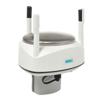
WXT530 Series User Guide M211840EN-D 2.1.4 WXT531 WXT531 measures rain. Figure 5 WXT531 sales@streamlinemeasurement.co.uk 01457-864334 www.streamlinemeasurement.co.uk... -
Page 18: Components
Chapter 2 – Product Overview 2.2 Components Figure 6 WXT536 Components Fixing screw and chassis grounding point Screw cover Top of the transmitter Radiation shield Bottom of the transmitter sales@streamlinemeasurement.co.uk 01457-864334 www.streamlinemeasurement.co.uk... -
Page 19: Figure 7 Cut-Away View Of Wxt536
WXT530 Series User Guide M211840EN-D Figure 7 Cut-Away View of WXT536 Wind transducers (3 pcs) Precipitation sensor Pressure sensor inside the PTU module Humidity and temperature sensors inside the PTU module Service port sales@streamlinemeasurement.co.uk 01457-864334 www.streamlinemeasurement.co.uk... -
Page 20: Optional Features
8-pin M12 connector for power or data communications cable Alignment direction indicator arrow Fixing screw and chassis grounding point 2.3 Optional Features The WXT530 series includes the following optional features: • USB cables • Mounting kit • Surge protector • Bird kit •... -
Page 21: Usb Cables
WXT530 Series User Guide M211840EN-D 2.3.1 USB Cables Figure 9 USB Cable • USB RS-232/RS-485 cable with 8-pin M12 threaded connector (1.4 m) • USB service cable with 4-pin M8 threaded connector (1.4 m) The service cable, while connected between the service port and PC, forces the service port to RS-232 / 19200, 8, N, 1. -
Page 22: Mounting Kit
The optional mounting kit helps mounting the transmitter on a pole mast. When using the mounting kit, alignment is needed only when mounting for the first time. Using the mounting kit improves the transmitter IP classification to IP66. Without the mounting kit, the WXT530 series transmitters are rated IP65. sales@streamlinemeasurement.co.uk 01457-864334... -
Page 23: Surge Protector
Vaisala provides the following surge protectors: • Vaisala Surge Protector WSP150. A compact transient overvoltage suppressor designed for outdoor use. It can be used with all Vaisala wind and weather instruments. Install WSP150 close to the protected instrument (maximum 3 m). -
Page 24: Bird Kit
Chapter 2 – Product Overview 2.3.4 Bird Kit Figure 12 Bird Kit The optional bird kit reduces the interference that birds cause to the wind and rain measurement. The kit consists of a metallic band with spikes pointing upward. The kit is installed on top of the transmitter. -
Page 25: Vaisala Configuration Tool
When the kit is in place, more snow can accumulate on the transmitter, and the snow can melt away more slowly. 2.3.5 Vaisala Configuration Tool Vaisala Configuration Tool is a Windows-based, user-friendly parameter setting software for WXT530 transmitters. It is also fully compatible with WMT52 and WXT520. Figure 14 Vaisala Configuration Tool 2.3.6 Sensor Heating... -
Page 26: Backward Compatibility
IEC 60945 Maritime Navigation and Radiocommunication Equipment and Systems - General requirements - Methods of testing. • The WXT530 series is in conformance with the provisions of the RoHS directive of the European Union: • Directive on the Restriction of the Use of Certain Hazardous Substances in Electrical and Electronic Equipment (2002/95/EC) sales@streamlinemeasurement.co.uk... - Page 27 WXT530 Series User Guide M211840EN-D sales@streamlinemeasurement.co.uk 01457-864334 www.streamlinemeasurement.co.uk...
-
Page 28: Functional Description
✔ ✔ The transmitters use Vaisala WINDCAP sensor technology for wind measurement. The wind sensor has an array of three equally spaced ultrasonic transducers on a horizontal plane. The unit determines wind speed and wind directions by measuring the time it takes the ultrasound to travel from one transducer to the other two. -
Page 29: Precipitation Measurement Principle
✔ ✔ ✔ The transmitter uses Vaisala RAINCAP Sensor 2-technology in precipitation measurement. The precipitation sensor comprises of a steel cover and a piezoelectrical sensor mounted on the bottom surface of the cover. The precipitation sensor detects the impact of individual raindrops. The signals from the impact are proportional to the volume of the drops. -
Page 30: Ptu Measurement Principle
Chapter 3 – Functional Description Precipitation current intensity is internally updated every 10 seconds and represents the intensity during the one minute period before requesting/automatic precipitation message sending (for fast reactions to a rain event, during the first minute of the rain event, the intensity is calculated over the period rain has lasted in 10-second steps instead of a fixed period of one minute). -
Page 31: Heating
WXT530 Series User Guide M211840EN-D 3.4 Heating WXT536 WXT535 WXT534 WXT533 WXT532 WXT531 ✔ ✔ ✔ ✔ ✔ When operating the sensor in temperatures below 0 °C (32 °F), select a model with an internal heater and enable the heater for operation. -
Page 32: Analog Input Interface
Chapter 3 – Functional Description 3.5 Analog Input Interface WXT536 WXT535 WXT534 WXT533 WXT532 WXT531 ✔ WXT536 offers an analog input option for solar radiation, external temperature, level measurement, and tipping bucket. Figure 15 Analog Inputs for External Sensors Analog input 1 Sensor A: Solar radiation Analog input 2 Sensor B: Temperature... - Page 33 WXT530 Series User Guide M211840EN-D sales@streamlinemeasurement.co.uk 01457-864334 www.streamlinemeasurement.co.uk...
-
Page 34: Installation
To prevent corrosion and oxidation, use copper paste or equivalent on screws and connector threads. 4.1.1 Maritime Installations In maritime installations according to IEC 60945, the WXT530 series belongs to the installation category C, which means that it is exposed to weather. When making maritime installations, pay attention to the following: •... -
Page 35: Figure 16 Recommended Mast Location In Open Area
WXT530 Series User Guide M211840EN-D Following World Meteorological Organization (WMO) guidelines, a general recommendation is that there is at least 150 m open area in all directions from the mast. Any object of height (h) does not significantly disturb wind measurement at a minimum distance of 10 times the height of the object. -
Page 36: Figure 17 Recommended Mast Length On Top Of Building
Additional protection is needed in regions with frequent, severe thunderstorms, especially when long line cables (> 30 m) are used. Vaisala recommends using a surge protector, such as WSP150 and WSP152, in all sites with an elevated risk of lightning strike. -
Page 37: Unpacking Wxt530
WXT530 Series User Guide M211840EN-D 4.3 Unpacking WXT530 The transmitter comes in a custom shipping container. The following figure shows the contents of the carton. Figure 18 Contents of Shipping Container Protective packaging top Shipping carton Inner box Manual, cables, mounting kit (optional) -
Page 38: Figure 19 Installing With Protective Packaging
Chapter 4 – Installation CAUTION! Be careful not to damage the wind transducers located at the top of the three antennas. Dropping the device can break or damage the transducers. If the antenna bends or twists, re-aligning can be difficult or impossible. Do not remove the top of the package protecting the transducer until you have installed the transmitter. -
Page 39: Mounting Wxt530
WXT530 Series User Guide M211840EN-D 4.4 Mounting WXT530 The transmitter is easy to install as it does not have any moving parts. The transmitter can be mounted on: • Vertical pole mast • Sensor support arm Install the transmitter upright. The transmitter radiation shield reflects light. If you install the transmitter next to a pyranometer or a temperature and humidity sensor, the pyranometer or temperature and humidity sensor can give incorrect measurements. -
Page 40: Mounting Wxt530 On Vertical Pole Mast Without Mounting Kit
Chapter 4 – Installation 4.4.1 Mounting WXT530 on Vertical Pole Mast without Mounting Kit 1. Remove the screw cover and insert the transmitter to the pole mast. 2. Align the transmitter so that the arrow points to North. 3. Tighten the fixing screw and replace the screw cover. 4.4.2 Mounting WXT530 on Vertical Pole Mast with Mounting 2.5‑mm and 5‑mm Allen keys When mounting a transmitter on a pole mast, you can use an optional mounting kit to ease... -
Page 41: Figure 20 Mounting Wxt531 On Vertical Pole Mast
WXT530 Series User Guide M211840EN-D Figure 20 Mounting WXT531 on Vertical Pole Mast CAUTION! Handle with care. Any impact on the instrument or sensor array may cause damage and lead to incorrect measurements. 1. Remove the adapter sleeve from the mounting kit. - Page 42 Chapter 4 – Installation 3. Insert the mounting kit adapter to the transmitter bottom. Protective cushion Transmitter Mounting kit Pole 4. Turn the kit firmly until you feel the adapter snap into the locked position. sales@streamlinemeasurement.co.uk 01457-864334 www.streamlinemeasurement.co.uk...
- Page 43 WXT530 Series User Guide M211840EN-D 5. Holding the sensor from its body, run the sensor cable through the mounting adapter, and slide the sensor onto the adapter. Do not tighten the fixing screw yet. Fixing screw. Tightening torque 1.5 Nm.
-
Page 44: Mounting Wxt530 On Sensor Support Arm
Chapter 4 – Installation 8. Remove the protective cushion. When removing a transmitter from the pole, turn the transmitter so that it snaps out from the mounting kit. Realignment is not needed when replacing the device. 4.4.3 Mounting WXT530 on Sensor Support Arm 10‑mm wrench If you use the optional mounting kit, you only need to align the sensor when mounting it for the first time. - Page 45 WXT530 Series User Guide M211840EN-D 3. Mount the transmitter on the sensor support arm. Nut M6 DIN 934 Mounting bolt M6 DIN 933 Screw cover Nut M6 DIN 934 Mounting bolt M6 DIN 933 sales@streamlinemeasurement.co.uk 01457-864334 www.streamlinemeasurement.co.uk...
-
Page 46: Grounding
Chapter 4 – Installation 4.5 Grounding A transmitter is typically grounded by installing it on a mast or a cross arm that provides a good connection to earth ground. As grounding is provided through the fixing screw (or mounting bolt), it is important that it makes a good ground connection. -
Page 47: Aligning Wxt530
WXT530 Series User Guide M211840EN-D 4. Insert the grounding kit through the hole in the seal. Make sure the nuts are tight so that the connector has a good connection. Seal Fixing screw 5. Connect the other end of the cable to a good grounding point. -
Page 48: Figure 21 Wxt530 North Arrow
Chapter 4 – Installation Figure 21 WXT530 North Arrow Wind direction can be referred either to true North, which uses the Earth’s geographic meridians, or to the magnetic North, which is read with a magnetic compass. The magnetic declination is the difference in degrees between the true North and magnetic North. The source for the magnetic declination should be current as the declination changes over time. -
Page 49: Aligning Wxt530 With Compass
WXT530 Series User Guide M211840EN-D 4.6.1 Aligning WXT530 with Compass • 2.5‑mm Allen key • Compass Do not remove the instrument or sensor from the mounting kit during alignment. 1. If the transmitter is mounted, loosen the fixing screw on the bottom of the transmitter so that you can rotate it. -
Page 50: Installing Vaisala Configuration Tool
‣ Mounting WXT530 on Sensor Support Arm (page 43) 4.7 Installing Vaisala Configuration Tool 1. Insert the WXT530 driver memory stick in the USB port. 2. Go to the WXT_Series_Conf_Tool folder and run WXTConf-2.41 r.3Setup.exe. 3. When Vaisala Configuration Tool Setup Wizard opens, select Next. sales@streamlinemeasurement.co.uk 01457-864334 www.streamlinemeasurement.co.uk... - Page 51 7. In the Select Additional Tasks window, select Additional Tasks and select Next. 8. In the Ready to Install window, select Install. Installing window opens. 9. Select Launch Vaisala Configuration Tool and select Finish to launch the tool. More Information ‣...
-
Page 52: Installing Usb Cable Driver
2. Insert the WXT530 driver memory stick in the USB port. 3. Go to the USB-driver folder and start installation by running setup.exe. 4. When Vaisala USB Device Driver Setup Wizard opens, select Next. 5. In the Select Additional Tasks window, select the tasks you want to perform and select Install. - Page 53 There is no reason to uninstall the driver for normal use. However, if you wish to remove the driver files and all Vaisala USB cable devices, uninstall the entry for Vaisala USB Instrument Driver from the program manager tool in the Windows Control Panel.
-
Page 54: Wiring And Power Management
Chapter 5 – Wiring and Power Management 5. Wiring and Power Management This chapter describes how to connect the power supply and the serial interfaces and how to manage and estimate power consumption. You can access the transmitter through the following serial interfaces: •... -
Page 55: Figure 23 Average Operational Current Consumption (With 4Hz Wind Sensor Sampling)
WXT530 Series User Guide M211840EN-D Figure 23 Average Operational Current Consumption (with 4Hz Wind Sensor Sampling) The input power supply must be capable of delivering 60 mA (at 12 V) or 100 mA (at 6 V) instant current spikes with duration of 30 ms. These are drawn by the wind sensor (whenever enabled) at 4 Hz rate, which is the default value for wind sampling. -
Page 56: Figure 24 Heating Instant Current And Power Vs Vh (Wxt536, Wxt535, Wxt533, And Wxt532)
Chapter 5 – Wiring and Power Management • 12 … 17 VAC (-10 % … +30 %) max 1.1 A for AC Figure 24 Heating Instant Current and Power vs Vh (WXT536, WXT535, WXT533, and WXT532) Figure 25 Heating Instant Current and Power vs Vh (WXT531) The power supply must meet the values shown above. -
Page 57: Power Management
WXT530 Series User Guide M211840EN-D WARNING! Make sure that you connect only de-energized wires. CAUTION! To avoid exceeding the maximum ratings in any condition, the voltages must be checked with no load at the power supply output. More Information ‣ Power Management (page 56) 5.2 Power Management... -
Page 58: Table 5 Economic Power Management
Chapter 5 – Wiring and Power Management Mode Standby PT1000 Level Tipping Solar Precipitation bucket radiation Continuous rain RS-232 1.5 mA +0.9 mA +0.1 mA +0.4 mA +0.1 mA +0.4 mA +0.4 mA RS-485 RS-422 SDI-21 continuous SDI-12 native 0.1 mA +0.9 mA +0.1 mA +0.4 mA... -
Page 59: Wiring With 8-Pin M12 Connector
WXT530 Series User Guide M211840EN-D Measurement Consumption ASCII RS-232 Data Adds 1 ... 2 mA to the standby consumption during the message sending time. Note transmission that the host device's input (data logger or PC) can constantly draw some current from the TX line. -
Page 60: Figure 26 Pins Of 8-Pin M12 Connector
Figure 26 Pins of 8-pin M12 Connector The following table shows the pin connections for the 8-pin M12 connector and the wire colors of the respective M12 cable (optional, 2/10 m). Table 6 Pin-outs for WXT530 Series Serial Interfaces and Power Supplies Wire Color M12 Pin#... -
Page 61: Table 8 Wxt532 Ma Output Option Screw Terminal Pin-Outs
WXT530 Series User Guide M211840EN-D Screw terminal RS-232 SDI-12 RS-485 RS-422 5 TX- Data out (TxD) Data out (Tx) Data - Data out (TX+) 4 RX+ Data in (Rx+) 3 RX- Data in (Rx-) 2 VIN- Vin- (operating) Vin- (operating) -
Page 62: Internal Wiring
Chapter 5 – Wiring and Power Management Screw terminal mA Output 2 VIN- Vin- (operating) 1 VIN+ Vin+ (operating) The terms "Default wiring" and "RS-422 wiring" refer to the internal wiring options. 5.3.2 Internal Wiring By default, the 8-pin M12 connector is wired for: •... -
Page 63: Table 10 Rs-485 Wiring
WXT530 Series User Guide M211840EN-D Table 10 RS-485 Wiring Internal Wiring External Wiring Pin # Internal Internal Connector Pin Internal Wiring External Wiring Connector Pin function for RS-485 for RS-485 for RS-485 VIN+ Vin + (Operating) Brown Brown VIN- Vin- (Operating GND) -
Page 64: Table 12 Rs-422 Wiring
Chapter 5 – Wiring and Power Management Table 12 RS-422 Wiring Internal Wiring External Wiring Pin # Internal Internal Connector Pin Internal Wiring External Wiring Connector Pin function for RS-422 for RS-422 for RS-422 VIN+ Vin+ (Operating) Brown Brown VIN- Vin- (Operating GND) Data in (RX-) Blue Blue... -
Page 65: Wiring Using Screw Terminals
WXT530 Series User Guide M211840EN-D Figure 27 Internal Wiring for RS-232, SDI-12, and RS-485 5.4 Wiring Using Screw Terminals 1. Loosen the 3 long screws at the bottom of the transmitter. sales@streamlinemeasurement.co.uk 01457-864334 www.streamlinemeasurement.co.uk... -
Page 66: Figure 28 Screw Terminal Block
Chapter 5 – Wiring and Power Management 2. Pull out the bottom part of the transmitter. 3. Insert the power supply wires and signal wires through the cable gland(s) in the bottom of the transmitter. Cable glands are included in the optional Bushing and Grounding Kit (222109). - Page 67 WXT530 Series User Guide M211840EN-D Screw RS-232 SDI-12 RS-485 RS-422 mA Output Terminal PIN 7 RXD Data in (RxD) Data in/out (Rx) Iout2 8 SGND Communication Communication Communication ground (GND) ground (GND) ground (GND) 9 HTG+ Vh+ (Heating) Vh+ (Heating)
-
Page 68: Data Communication Interfaces
600 m (2000 ft) or longer, you must use termination resistors at both ends of the line. The WXT530 series transmitters with serial communication interface have built-in termination options. Plain resistor (R) termination or termination with resistor connected series with capacitor can be selected with jumpers. -
Page 69: Figure 30 Termination Jumper Positions
WXT530 Series User Guide M211840EN-D Figure 30 Termination Jumper Positions NC, no termination R, 121 Ω termination RC, 121 Ω series with 4.7 nF capacitor termination The termination resistors increase power consumption significantly during data transmission. If low power consumption is a must, connect a 0.1 uF capacitor in series with each external termination resistor or use internal RC termination. -
Page 70: Connection Options
6.2 Connection Cables The following table shows the connection cable options for the WXT530 series transmitters. The USB cables connect the transmitter to a PC using a standard USB port. The USB cables also provide operation power to the transmitter when connected. -
Page 71: Connecting With Service Cable
217020 end wires end wires If you use the USB RS-232/RS-485 cable for a permanent installation, Vaisala recommends that you use the WSP152 surge protector to protect the host PC against surges entering through the USB port. 6.3 Connecting with Service Cable The USB service cable has a 4-pin M8 connector for service port. -
Page 72: Connecting Through M12 Bottom Connector Or Screw Terminal
3. Select the COM port reserved for the USB cable and select the following default communication settings: 19200, 8, N, 1. 4. Use the Vaisala Configuration Tool or a terminal program to make the configuration changes. 5. When removing the service cable, support the transmitter while pulling the 4-pin M8 connector for service port. -
Page 73: Communication Setting Commands
WXT530 Series User Guide M211840EN-D Serial Interface Serial Settings RS-485 ASCII 19200 baud, 8, N, 1 RS-422 ASCII 19200 baud, 8, N, 1 RS-422 NMEA 4800 baud, 8, N, 1 6.4 Communication Setting Commands In this section, the commands the user types are presented in normal text while the responses of the transmitter are presented in italic. -
Page 74: Settings Fields
You can add the Id information field in the supervisor data message to provide identifying information in addition to the transmitter address. The information field is set as part of the factory settings. You can only modify it with the Vaisala Configuration Tool. More Information ‣... - Page 75 Software version: for example, 1.00 (read-only) Parameter locking 0 = Parameters can be changed 1 = Parameters locked. Vaisala recommends that you set this parameter to 1 after you have configuration. This prevents accidental changes, for instance, in RS- 485 use when there is interference.
-
Page 76: Changing The Communication Settings (Axu)
Chapter 6 – Connection Options 6.4.3 Changing the Communication Settings (aXU) Use this command to change communication settings. Command format in ASCII and NMEA 0183: aXU,A=x,M=x,C=x,I=x,B=x,D=x,P=x,S=x,L=x<cr><lf> Command format in SDI-12: aXXU,A=x,M=x,C=x,I=x,B=x,D=x,P=x,S=x,L=x! A, M, C, I, B, D, The communication setting fields. P, S,L Input value for the setting <cr><lf>... - Page 77 WXT530 Series User Guide M211840EN-D 1XU<cr><lf> 1XU,A=1,M=P,T=1,C=2,I=0,B=19200,D=8,P=N,S=1,L=25, N=WXT530V=1.00<cr><lf> Example (ASCII, device address 0): Changing RS-232 serial interface with ASCII, polled communication protocol and baud settings 19200, 8, N, 1 to RS-485 serial interface with ASCII, automatic protocol and baud settings 9600, 8, N, 1.
-
Page 78: Retrieving Data Messages
Chapter 7 – Retrieving Data Messages 7. Retrieving Data Messages Each communication protocol has its own section for data message commands. Type commands in CAPITAL letters. The parameter order in messages is as follows: Wind (M1): Dn Dm Dx Sn Sm Sx PTU (M2): Ta Tp Ua Pa Rain (M3): Rc Rd Ri Hc Hd Hi Rp Hp Supv (M5): Th Vh Vs Vr Id... -
Page 79: Precipitation Counter Reset (Axzru)
WXT530 Series User Guide M211840EN-D <cr><lf> Command terminator in ASCII and NMEA 0183 Command terminator in SDI-12 The response depends on the communication protocol as shown in the examples. Example (ASCII): 0XZ<cr><lf> 0TX,Start-up<cr><lf> Example (SDI-12): 0XZ!0<cr><lf> (=device address) Example (NMEA 0183): 0XZ<cr><lf>... -
Page 80: Precipitation Intensity Reset (Axzri)
Chapter 7 – Retrieving Data Messages Example (ASCII): 0XZRU<cr><lf> 0TX,Rain reset<cr><lf> Example (SDI-12): 0XZRU!0<cr><lf> (= device address) Example (NMEA 0183): 0XZRU<cr><lf> $WITXT,01,01,10,Rain reset*26<cr><lf> 7.1.3 Precipitation Intensity Reset (aXZRI) This command resets the rain and hail intensity parameters Ri, Rp, Hi, and Hp. Command format in ASCII and NMEA 0183: aXZRI<cr><lf>... -
Page 81: Measurement Reset (Axzm)
WXT530 Series User Guide M211840EN-D 0XZRI<cr><lf> 0TX,Inty reset<cr><lf> Example (SDI-12): 0XZRI!0<cr><lf> (= device address) Example (NMEA 0183): 0XZRI<cr><lf> $WITXT,01,01,11,Inty reset*39<cr><lf> 7.1.4 Measurement Reset (aXZM) This command interrupts all ongoing measurements except rain measurement and restarts them. Command format in ASCII and NMEA 0183: aXZM<cr><lf>... -
Page 82: Ascii Protocol
Chapter 7 – Retrieving Data Messages Example (SDI-12): 0XZM!0 (= device address) Example (NMEA 0183): 0XZM<cr><lf> $WITXT,01,01,09,Measurement reset*50<cr><lf> 7.2 ASCII Protocol 7.2.1 Abbreviations and Units Table 18 Abbreviations and Units Abbreviation Name Unit Status Wind speed minimum m/s, km/h, mph, knots #, M, K, S, N Wind speed average m/s, km/h, mph, knots #, M, K, S, N... -
Page 83: Device Address (?)
WXT530 Series User Guide M211840EN-D Abbreviation Name Unit Status Hail peak intensity #, M, I, H hits/cm h, hits/in hits/h Heating temperature °C, °F #, C, F Heating voltage #, N, V, W, F Supply voltage 3.5 V ref. voltage... -
Page 84: Acknowledge Active Command (A)
Chapter 7 – Retrieving Data Messages If more than one transmitter is connected to the bus, see A.1 Connecting Several Transmitters on Same Bus (page 171). 7.2.3 Acknowledge Active Command (a) This command checks that a device responds to a data recorder or another device. It asks a sensor to acknowledge its presence on the bus. -
Page 85: Pressure, Temperature And Humidity Data Message (Ar2)
WXT530 Series User Guide M211840EN-D <cr><lf> Command terminator Example of the response (the parameter set is configurable): 0R1,Dn=236D,Dm=283D,Dx=031D,Sn=0.0M,Sm=1.0M, Sx=2.2M<cr><lf> Device address Wind message query command Wind direction minimum (D = degrees) Wind direction average (D = degrees) Wind direction maximum (D = degrees) -
Page 86: Precipitation Data Message (Ar3)
Chapter 7 – Retrieving Data Messages Relative humidity (P = % RH) Air pressure (H = hPa) <cr><lf> Response terminator 7.2.6 Precipitation Data Message (aR3) This command requests the precipitation data message. Command format: aR3<cr><lf> Device address Precipitation message query command <cr><lf>... -
Page 87: Combined Data Message (Ar)
Response terminator Information field The content of the parameter Id is a text string which you can modify with the Vaisala Configuration Tool. The field can include customer-specific, additional information. For more information on changing the settings, see the Vaisala Configuration Tool online help for the Info field in the Device Settings window. -
Page 88: Composite Data Message Query (Ar0)
Chapter 7 – Retrieving Data Messages Device address (default = 0) Combined message query command <cr><lf> Command terminator Example of the response: 0R1,Dm=027D,Sm=0.1M<cr><lf> 0R2,Ta=74.6F,Ua=14.7P,Pa=1012.9H<cr><lf> 0R3,Rc=0.10M,Rd=2380s,Ri=0.0M,Hc=0.0M,Hd=0s, Hi=0.0M<cr><lf> 0R5,Th=76.1F,Vh=11.5N,Vs=11.5V,Vr=3.510V,Id=HEL___<cr><lf> 7.2.9 Composite Data Message Query (aR0) This command requests a combined data message with user-configurable set of wind, pressure, temperature, humidity, precipitation, and supervisor data. - Page 89 WXT530 Series User Guide M211840EN-D ar1xxx<cr><lf> Device address Wind message query command Three-character CRC for ar1 command <cr><lf> Command terminator Example of the response (the parameter set is configurable): 0r1,Dn=236D,Dm=283D,Dx=031D,Sn=0.0M,Sm=1.0M,Sx=2.2MLFj<cr><lf> The three characters before <cr><lf> are the CRC for the response.
-
Page 90: Automatic Mode
Chapter 7 – Retrieving Data Messages Correct three-character CRC for the ar1 command Three-character CRC for the response message <cr><lf> Response terminator Example of the other data query commands with CRC (when the device address is 0): Parameter Description Pressure, humidity and 0r2Gje<cr><lf>... -
Page 91: Automatic Composite Data Message (Ar0)
WXT530 Series User Guide M211840EN-D 0r1,Sn=0.1M,Sm=0.1M,Sx=0.1MGOG<cr><lf> 0r2,Ta=22.7C,Ua=55.5P,Pa=1004.7H@Fn<cr><lf> 0r3,Rc=0.00M,Rd=0s,Ri=0.0MIlm<cr><lf> 0r5,Th=25.0C,Vh=10.6#,Vs=10.8V,Vr=3.369VO]T<cr><lf> Stop the automatic output by changing the communication protocol to polled mode (aXU,M=P). You can also use polling commands aR1, aR2, aR3, and aR5 in ASCII automatic protocol for requesting data. -
Page 92: Address Query Command (?)
Chapter 7 – Retrieving Data Messages In particular, wind measurement typically consumes 60 mW average power (with 4 Hz sampling rate), throughout the averaging period. In the Continuous mode (aXU=M,R) the power consumption is determined by the internal update intervals of the sensors and wind averaging time. -
Page 93: Change Address Command (Aab)
WXT530 Series User Guide M211840EN-D Device address Command terminator Response: a<cr><lf> Device address <cr><lf> Response terminator Example: 0!0<cr><lf> 7.3.3 Change Address Command (aAb) This command changes the device address. After the command has been issued and responded to, the sensor is not required to respond to another command for one second to ensure writing the new address to the non-volatile memory. -
Page 94: Send Identification Command (Ai)
Chapter 7 – Retrieving Data Messages Device address = the new address (or the original address, if the device is unable to change it) <cr><lf> Response terminator Example (changing address from 0 to 3): 0A3!3<cr><lf> 7.3.4 Send Identification Command (aI) This command queries the device for the SDI-12 compatibility level, model number, firmware version, and serial number. -
Page 95: Start Measurement Command (Am)
WXT530 Series User Guide M211840EN-D 0I!013VAISALA_WXT530103Y2630000<cr><lf> 7.3.5 Start Measurement Command (aM) This command asks the device to make a measurement. The measured data is not sent automatically. You must request it with the Send data command aD. The host device is not allowed to send any commands to other devices on the bus until the measurement is completed. -
Page 96: Start Measurement Command With Crc (Amc)
Chapter 7 – Retrieving Data Messages Part two (indicates that the data is ready to be requested): a<cr><lf> Device address The measurement completing time in seconds The number of the measured parameters available (maximum number is 9) <cr><lf> Response terminator When the measurement takes less than one second, part two of the response is not sent. -
Page 97: Start Concurrent Measurement (Ac)
WXT530 Series User Guide M211840EN-D 7.3.7 Start Concurrent Measurement (aC) Use this command when there are several devices on the same bus and simultaneous measurements are needed from the devices, or if more than 9 measurement parameters are requested from a single device. -
Page 98: Start Concurrent Measurement With Crc (Acc)
Chapter 7 – Retrieving Data Messages 7.3.8 Start Concurrent Measurement with CRC (aCC) Command format: aCCx! Use this command when there are several devices on the same bus and simultaneous measurements are needed from the devices but a three-character CRC is added to the response data strings before <cr><lf>. -
Page 99: Examples Of Am, Ac And Ad Commands
WXT530 Series User Guide M211840EN-D <cr><lf> Response terminator aD0 command can also be used to break the measurement in progress started with commands aM, aMC, aC, or aCC. In SDI-12 v1.3 Continuous measurement mode (aXU,M=R) the sensor makes measurements at configurable update intervals. The aD command following the aM, aMC, aC, or aCC command always returns the latest updated data. - Page 100 Chapter 7 – Retrieving Data Messages 0D0!0+339+018+030+0.1+0.1+0.1<cr><lf> Example 2: Start a concurrent pressure, humidity and temperature measurement and request the data: 0C2!000503<cr><lf> (measurement ready in 5 seconds and 3 parameters available, for aC command device address not sent as a sign of a completed measurement) 0D0!0+23.6+29.5+1009.5<cr><lf>...
-
Page 101: Continuous Measurement (Ar)
WXT530 Series User Guide M211840EN-D Start a composite measurement and request the data. The configuration of the parameter set is such that 9 parameters are available. Thus start measurement command aM can be used. Due to the 35-character limit in response message, aD0 returns only 6 parameters. The remaining parameters are retrieved with aD1. - Page 102 Chapter 7 – Retrieving Data Messages For using Continuous measurement commands for all WXT530 series parameters (wind, PTU, precipitation, and supervisor) the select the respective protocol (aXU,M=R). The M=S selection requires use of aM, aMC, aC, aCC, and aD commands, only the precipitation data can be retrieved continuously (using aR3 command).
-
Page 103: Continuous Measurement With Crc (Arc)
WXT530 Series User Guide M211840EN-D 0R1!0+323+331+351+0.0+0.4+3.0<cr><lf> 0R3!0+0.15+20+0.0+0.0+0+0.0+0.0+0.0<cr><lf> 0R!0+178+288+001+15.5+27.4+38.5+23.9+35.0+1002.1+0.00+0+0.0+23.8<cr><lf> 7.3.12 Continuous Measurement with CRC (aRC) Command format: aRCx! The device can be configured so that all the parameters can be requested instantly with the command aRC but a three-character CRC is added to the response data strings before <cr><lf>. -
Page 104: Acknowledge Active Command (A)
Chapter 7 – Retrieving Data Messages Response: b<cr><lf> Device address (default = 0) <cr><lf> Response terminator. Example: ?<cr><lf> 0<cr><lf> If more than one transmitter is connected to the bus, see A.1 Connecting Several Transmitters on Same Bus (page 171). 7.4.2 Acknowledge Active Command (a) This command checks that a device responds to a data recorder or another device. -
Page 105: Mwv Wind Speed And Direction Query
WXT530 Series User Guide M211840EN-D 0<cr><lf> 0<cr><lf> 7.4.3 MWV Wind Speed and Direction Query Use the MWV query command to request the wind speed and direction data. To use the MWV query, the NMEA Wind formatter parameter in the wind sensor settings must be set to W. -
Page 106: Xdr Transducer Measurement Query
Wind direction is given in relation to the devices north-south axis. An offset value to the measured direction can be set, see Chapter 8. The checksum typed in the query depends on the device identifier characters. To find the correct checksum in the WXT530 series transmitters, type any three characters after the $--WIQ,MWV command. Example If you type the command $--WIQ,MWVxxx<cr><lf>(xxx arbitrary characters) , the... - Page 107 WXT530 Series User Guide M211840EN-D Device identifier of the requester Device type identifier (WI = weather instrument) Defines the message as Query Transducer measurement command Checksum delimiter Two-character checksum for the query command. <cr><lf> Command terminator The response includes the parameters activated in the data messages.
-
Page 108: Table 19 Transducer Ids Of Measurement Parameters
(0 ... 9, A = 10, B = 11, a = 36, b = 37 etc.) The checksum to be typed in the query depends on the device identifier characters and can be asked from the WXT530 Series, see example below. Example: Typing the command $--WIQ,XDRxxx<cr><lf>... - Page 109 WXT530 Series User Guide M211840EN-D Measurement Transducer ID Type Rain accumulation Rain duration Rain current intensity Hail accumulation Hail duration Hail current intensity Rain peak intensity Hail peak intensity Heating temperature Supply voltage Heating voltage 3.5 V reference voltage Information field Aux.
- Page 110 Chapter 7 – Retrieving Data Messages $WIXDR,C,23.3,C,0,C,24.0,C,1,H,50.1,P,0,P,1009.5,H, 0*75<cr><lf> Precipitation data $WIXDR,V,0.02,M,0,Z,30,s,0,R,2.7,M,0,V,0.0,M,1,Z,0,s,1,R,0.0,M,1, R,6.3,M,2,R, 0.0,M,3*51<cr><lf> Supervisor data $WIXDR,C,20.4,C,2,U,12.0,N,0,U,12.5,V,1,U,3.460,V,2,G,HEL/___,,4*2D The structure of the wind sensor response message: Start of the message Device type (WI = weather instrument) Transducer measurement response identifier Transducer id 0 type (wind direction) Transducer id 0 data (min wind direction) Transducer id 0 units (degrees, min wind direction) Transducer id for min wind direction...
- Page 111 WXT530 Series User Guide M211840EN-D Transducer id for average wind speed Transducer id 2 type (wind speed) Transducer id 2 data (max wind speed) Transducer id 2 units (m/s, max wind speed) Transducer id for max wind speed Checksum delimiter Two-character checksum for the response <cr><lf>...
- Page 112 Chapter 7 – Retrieving Data Messages Start of the message Device type (WI = weather instrument) Transducer measurement response identifier Transducer id 0 type (Accumulated rainfall) 0.02 Transducer id 0 data (Accumulated rainfall) Transducer id 0 units (mm, Accumulated rainfall) Transducer id for Accumulated rainfall Transducer id 0 type (Rain duration) Transducer id 0 data (Rain duration)
- Page 113 WXT530 Series User Guide M211840EN-D Transducer id for Hail peak intensity Checksum delimiter Two-character checksum for the response <cr><lf> Response terminator The structure of the supervisor response message: Start of the message Device type (WI = weather instrument) Transducer measurement response identifier Transducer id 2 type (temperature), see the following Transducer table 20.4...
-
Page 114: Txt Text Transmission
Chapter 7 – Retrieving Data Messages Table 20 Transducer Table Transducer Type Units Field Comments Temperature C = Celsius F = Fahrenheit Angular displacement (wind D = degrees direction) Wind speed K = km/h S = mph, non-standardized M = m/s N = knots Pressure B = bars... -
Page 115: Automatic Mode
WXT530 Series User Guide M211840EN-D Talker identifier (WI = weather instrument) Text transmission identifier. Total number of messages, 01 to 99 Message number. Text identifier (see text message table) c---c Text message (see text message table) Checksum delimiter Two-character checksum for the query command. -
Page 116: Automatic Composite Data Message (Ar0)
Chapter 7 – Retrieving Data Messages 7.4.7 Automatic Composite Data Message (aR0) When automatic composite data messaging is selected, the transmitter sends composite data messages at user-configurable intervals. The message structure is the same as with the composite data query command aR0 and contains a user configurable set of wind, pressure, temperature, humidity, precipitation, and supervisor data. - Page 117 WXT530 Series User Guide M211840EN-D sales@streamlinemeasurement.co.uk 01457-864334 www.streamlinemeasurement.co.uk...
-
Page 118: Sensor And Data Message Settings
This chapter lists the sensor configuration and data message formatting commands for all communications protocols: • ASCII • NMEA 0183 • SDI-12 You can also modify sensor and data message settings with the Vaisala Configuration Tool. More Information ‣ Error Messaging/Text Messages (page 153) 8.1.1 Wind Sensor WXT536... - Page 119 WXT530 Series User Guide M211840EN-D Command terminator in SDI-12 The response in ASCII and NMEA 0183: aWU,R=[R],I=[I],A=[A],G=[G],U=[U],D=[D],N=[N],F=[F]<cr><lf> The response in SDI-12: aXWU,R=[R],I=[I],A=[A],G=[G],U=[U],D=[D],N=[N],F=[F]<cr><lf> where [R][I][A][G][U][D][N] are the setting fields. Example (ASCII and NMEA 0183, device address 0): 0WU<cr><lf> 0WU,R=01001000&00100100,I=60,A=10,G=1,U=N,D= -90,N=W,F=4<cr><lf> Example (SDI-12, device address 0): 0XWU!0XWU,R=11111100&01001000,I=10,A=3,G=1,U=M,D=0,N=W,F=4<cr><lf>...
-
Page 120: Table 21 Wind Parameters Bits 1-8
Chapter 8 – Sensor and Data Message Settings Table 21 Wind Parameters Bits 1-8 Description 1st bit (most left) Dn Direction minimum 2nd bit Dm Direction average 3rd bit Dx Direction maximum 4th bit Sn Speed minimum 5th bit Sm Speed average 6th bit Sx Speed maximum 7th bit... - Page 121 WXT530 Series User Guide M211840EN-D Parameter Description Averaging time: 1 ... 3600 seconds Defines the period over which the wind speed and direction averaging is calculated. Same period is also used for maximum and minimum calculation. See Appendix D Wind Measurement Averaging Method on page 201 for difference in averaging practices when A<I and A>I.
- Page 122 Chapter 8 – Sensor and Data Message Settings Command format in SDI-12: aXWU, R=x,I=x,A=x,G=x,U=x,D=x,N=x,F=x! R, I, A, G, U, D, Wind sensor setting fields. N, F Value for the setting <cr><lf> Command terminator in ASCII and NMEA 0183 Command terminator in SDI-12 If averaging time [A] is greater than update interval [I], it is a multiple of the update interval and at maximum 12 times greater.
-
Page 123: Pressure, Temperature, And Humidity Sensors
WXT530 Series User Guide M211840EN-D 0WU,R=0100100001001000<cr><lf> 0WU,R=01001000&00100100<cr><lf> Character '&' is not allowed in the command. The wind message response after the change above: 0R1<cr><lf> 0R1,Dm=268D,Sm=1.8N<cr><lf> Example (SDI-12, device address 0): Changing the measurement interval to 10 seconds: 0XWU,I=10!0<cr><lf> In SDI-12 mode a separate enquiry (0XWU!) must be given to check the data. - Page 124 Chapter 8 – Sensor and Data Message Settings Device address Pressure, temperature and humidity sensor settings command in ASCII and NMEA 0183 Pressure, temperature and humidity sensor settings command in SDI-12 <cr><lf> Command terminator in ASCII and NMEA 0183 Command terminator in SDI-12 The response in ASCII and NMEA 0183: aTU,R=[R],I=[I],P=[P],H=[H]<cr><lf>...
-
Page 125: Table 23 Ptu Parameters Bits 1-8
WXT530 Series User Guide M211840EN-D Table 23 PTU Parameters Bits 1-8 Description 1st bit (most left) Pa Air pressure 2nd bit Ta Air temperature 3rd bit Tp Internal temperature 4th bit Ua Air humidity 5th bit spare 6th bit spare 7th bit... - Page 126 Chapter 8 – Sensor and Data Message Settings Parameter Description Temperature unit: C = Celsius, F = Fahrenheit <cr><lf> Response terminator NMEA formatter: T = XDR (transducer syntax) D =MDA Defines whether the wind message is sent in XDR or MDA format. 8.1.2.3 Changing the Settings (aTU) You can change the following settings: •...
- Page 127 WXT530 Series User Guide M211840EN-D An example of MDA: $WIMDA,29.88,I,1.0120,B,22.5,C,,C,31.5,,,C,,T,,M,,N,,M*3F Examples (ASCII and NMEA 0183, device address 0) You need the temperature and humidity data to be available in every 30 seconds Changing the parameter selection: 0TU,R=0101000001010000<cr><lf> 0TU,R=01010000&01010000<cr><lf> Character '&' is not allowed in the command.
-
Page 128: Precipitation Sensor
Chapter 8 – Sensor and Data Message Settings 8.1.3 Precipitation Sensor WXT536 WXT535 WXT534 WXT533 WXT532 WXT531 ✔ ✔ ✔ ✔ 8.1.3.1 Checking the Settings (aRU) Use this command to check the current precipitation sensor settings. Command format in ASCII and NMEA 0183: aRU<cr><lf>... -
Page 129: Table 25 Precipitation Parameters Bits 1-8
WXT530 Series User Guide M211840EN-D Example (SDI-12, device address 0): 0RU!0RU,R=11111100&10000000,I=60,U=M,S=M,M=R, Z=M,X=100,Y=100<cr><lf> 8.1.3.2 Setting Fields Parameter Description Parameter selection: This field consists of 16 bits defining the precipitation parameters included in the data messages. The bit value 0 disables and the bit value 1 enables the parameter. -
Page 130: Table 26 Precipitation Parameters Bits 9-16
Chapter 8 – Sensor and Data Message Settings Table 26 Precipitation Parameters Bits 9-16 Description 9th bit Rc Rain amount 10th bit Rd Rain duration 11th bit Ri Rain intensity 12th bit Hc Hail amount 13th bit Hd Hail duration 14th bit Hi Hail intensity 15th bit Rp Rain peak... - Page 131 WXT530 Series User Guide M211840EN-D Parameter Description Counter reset: M = manual, A = automatic, L= limit Y = immediate M = manual reset mode: The counter is reset with aXZRU command. See 7.1.2 Precipitation Counter Reset (aXZRU) (page 78).
- Page 132 Chapter 8 – Sensor and Data Message Settings • Hail accumulation limit. Make the desired setting with the following command. Select the correct value/letter for the setting fields. Command format in ASCII and NMEA 0183: aRU,R=x,I=x, U=x,S=x,M=x,Z=x, X=x, Y=x<cr><lf> Command format in SDI-12: aXRU,R=x,I=x,U=x,S=x,M=x,Z=x, X=x,Y=x! R, I, U, S, M, Z, Precipitation sensor setting fields.
-
Page 133: Supervisor Message
WXT530 Series User Guide M211840EN-D 0R3<cr><lf> 0R3,Rc=0.00M,Ri=0.0M<cr><lf> Example (SDI-12, device address 0): Changing the counter reset mode (resets the precipitation counters): 0XRU,Z=M!0<cr><lf> More Information ‣ Setting Fields (page 128) 8.1.4 Supervisor Message 8.1.4.1 Checking the Settings (aSU) Use this command to check the current supervisor settings. -
Page 134: Table 27 Supervisor Parameters Bits 1-8
Chapter 8 – Sensor and Data Message Settings aXSU,R=[R],I=[I],S=[S],H=[Y]<cr><lf> 8.1.4.2 Setting Fields Parameter Description Parameter selection: This field consists of 16 bits defining the supervisor parameters included in the data messages. The bit value 0 disables and the bit value 1 enables the parameter. Bits 1-8 determine the parameters included in the message obtained with the following commands: •... -
Page 135: Table 28 Supervisor Parameters Bits 9-16
WXT530 Series User Guide M211840EN-D Table 28 Supervisor Parameters Bits 9-16 Description 9th bit Th Heating temperature 10th bit Vh Heating voltage 11th bit Vs Supply voltage 12th bit Vr 3.5 V reference voltage 13th bit Id Information field 14th bit... -
Page 136: Composite Data Message (Ar0)
Chapter 8 – Sensor and Data Message Settings Make the desired setting with the following command. Select the correct value/letter for the setting fields. Command format in ASCII and NMEA 0183: aSU,R=x,I=x,S=x,H=x<cr><lf> Command format in SDI-12; aXSU,R=x,I=x,S=x,H=x! R, I, S, H The supervisor setting fields. -
Page 137: Analog Input
WXT530 Series User Guide M211840EN-D To format a composite data message with average wind direction, average wind speed, temperature, humidity and pressure data when the original composite data message contains following data: maximum wind direction, maximum wind speed, temperature, humidity, pressure, accumulated rainfall, supply voltage and heating voltage: 0R0<cr><lf>... -
Page 138: Figure 32 Analog Input Connector Pins
Differential 0 … 25 mV input, + Pyranometer Differential 0 … 25 mV input, - Pyranometer WS IN 0 … 2.5/0 … 5/0 … 10 V input Level sensor The following figure shows the analog input settings in Vaisala Configuration Tool. sales@streamlinemeasurement.co.uk 01457-864334 www.streamlinemeasurement.co.uk... -
Page 139: Figure 33 Analog Input Settings In Vaisala Configuration Tool
WXT530 Series User Guide M211840EN-D Figure 33 Analog Input Settings in Vaisala Configuration Tool Table 30 Analog Input Setting Definitions Setting Default value Definition Update interval 1 min Defines analog input measurement interval. A shorter interval and a longer averaging time increase power consumption. - Page 140 • Ultrasonic level sensor range 5 V • Ultrasonic level sensor gain 1 • Aux temperature average time 1 s • Aux rain counter reset: manual • Aux rain gain 0.2 (for 0.2 mm per tip) WXT530 Series settings: 0IU,R=11111000&11111000,I=60,A=3.0 0IB,G=100000.0 0IS,M=1,G=1.0 0IP,A=1.0 0IA,M=M,G=0.2...
-
Page 141: Table 31 Aiu Setting Fields [R]
WXT530 Series User Guide M211840EN-D 8.1.6.2 Common Sensor Settings (aIU) Update Interval [I] The update interval in seconds. This parameter defines the measurement interval for analog inputs: • Pt1000 • Solar radiation • Aux rain The range: 0.5 … 3600. 8.1.6.3 Aux Input Averaging Time [A] The Aux Input averaging time in seconds. - Page 142 The range: 0.000 000 001 … 1 000 000 For example, you can set aux rain gain for Vaisala RG13 Tipping Bucket Rain Gauge. The resolution is 0.1 mm per tip. Set the gain to 0.1 * 2 = 0.2 so that the Ra rain amount WXT reports is in millimeters.
- Page 143 WXT530 Series User Guide M211840EN-D The initial tip counter overflows if it reaches 65536 and it starts from 0. If the tipping bucket resolution is 0.2 mm per tip, the gain is 0.2, and the maximum rain amount before overflow is 65536 ×...
-
Page 144: Analog Output
Chapter 8 – Sensor and Data Message Settings Averaging Time [A] The averaging time in seconds, resolution 0.5 s. You can set a short averaging time (0.5 s) to reduce the Pt1000 sensor self-heating. The message interval defines how often the measurement starts. -
Page 145: Table 32 Analog Output Scaling
WXT530 Series User Guide M211840EN-D Parameter Description aSU,g=4<cr><lf> Wind Direction Offset aSU,h=0<cr><lf> WD minimum aSU,j=22<cr><lf> WD maximum aSU,k=2<cr><lf> WD error indication The output o in mA is o=i* gain + offset. o is clamped between min and max. If wind measurement fails, the output value is err. - Page 146 Chapter 8 – Sensor and Data Message Settings Produced analog output (A) Measured wind speed or direction (in m/s or °) Selected gain value Selected offset value 8.1.7.3 Analog Output Signal for Wind Speed Channel The analog interfaces setup, default configuration: Current output 4 ...
-
Page 147: Table 33 Awu Setting Fields [R]
WXT530 Series User Guide M211840EN-D Table 33 aWU Setting Fields [R] Normal message st bit (most left) nd bit rd bit th bit th bit th bit th bit Analog output mode th bit & delimiter Composite message st bit (most left) -
Page 148: Maintenance
Do not use solvents or abrasive sponges when cleaning painted surfaces. 9.1.1 Cleaning the Radiation Shield Vaisala recommends that you clean the radiation shield once a year. 1. Clean the radiation shield with a soft cloth. Do not paint the radiation shield. - Page 149 WXT530 Series User Guide M211840EN-D 2. Loosen the 3 mounting screws at the bottom assembly of the transmitter and pull them out. Fixing screws Top of transmitter PTU module Latch Flat cable O-ring 3. Turn out the top of the transmitter.
- Page 150 Chapter 9 – Maintenance 7. Turn the top back in. Make sure the flat cable does not get stuck or squeezed between the top and the funnel for the flat cable and it is properly connected. 8. If the O-rings are damaged, replace them with new ones. 9.
- Page 151 WXT530 Series User Guide M211840EN-D sales@streamlinemeasurement.co.uk 01457-864334 www.streamlinemeasurement.co.uk...
-
Page 152: Troubleshooting
Chapter 10 – Troubleshooting 10. Troubleshooting Table 34 Data Validation Problem Possible causes Action(s) Wind measurement failure. Both Blockage (trash, leaves, branches, Remove the blockage, and check the speed and direction units are bird, snow, ice) between the wind that the wind transducers are not replaced by a # sign or the data transducers. -
Page 153: Table 35 Communication Problems
Data messages are not in The communication protocol may not Check the communication protocol of expected format. be the one you want. the device by using the Vaisala Configuration Tool or any terminal with command aXU,M! (SDI-12) aXU,M<cr><lf> (ASCII/NMEA) and change it if needed. -
Page 154: Self-Diagnostics
Chapter 10 – Troubleshooting Problem Possible causes Action(s) The transmitter keeps The polling address and the transmitter Set correct address either for the sending the message "TX address do not match. The transmitter is transmitter or to the polling request. Sync/address error". -
Page 155: Rain And Wind Sensor Heating Control
WXT530 Series User Guide M211840EN-D Table 36 Error Messaging/Text Messages Text message Text Message Interpretation and action identifier (in NMEA 0183 v3.0 protocol only) Unable to measure The requested parameters are not activated in the message and error check the parameter section fields. -
Page 156: Operating Voltage Control
Chapter 10 – Troubleshooting The heating temperature should stay above 0 °C when the heating is on (except in extremely cold conditions where the heating power is not sufficient). The heating voltage Vh should correspond to the heating voltage supplied. If there is a remarkable deviation, check the wiring. - Page 157 WXT530 Series User Guide M211840EN-D sales@streamlinemeasurement.co.uk 01457-864334 www.streamlinemeasurement.co.uk...
-
Page 158: Technical Specifications
Chapter 11 – Technical Specifications 11. Technical Specifications 11.1 Performance Table 37 WXT530 Series Barometric Pressure Measuring Specifications Property Description/Value Observation range 600 ... 1100 hPa Accuracy (for sensor element) ±0.5 hPa at 0 … +30 °C (+32 … +86 °F) ±1 hPa at -52 … +60 °C (-60 … +140 °F) Output resolution 0.1 hPa / 10 Pa / 0.001 bar / 0.1 mmHg / 0.01 inHg... -
Page 159: Table 40 Wxt530 Series Precipitation Measuring Specifications
WXT530 Series User Guide M211840EN-D Table 40 WXT530 Series Precipitation Measuring Specifications Description/Value Property Rainfall Cumulative accumulation after the latest automatic or manual reset. Collecting area 60 cm Output resolution 0.01 mm (0.001 in) Better than 5 %, weather-dependent Field accuracy for daily accumulation... -
Page 160: Inputs And Outputs
Update interval 1 ... 3600 s (= 60 min), at 1 s steps NTP (normal temperature and pressure) condition applied for wind tunnel testing. 11.2 Inputs and Outputs Table 42 WXT530 Series Electrical Specifications Property Description/Value Operating voltage 6 ... 24 VDC (-10 % ... +30 %) -
Page 161: Table 43 Wxt536 Analog Input Options
WXT530 Series User Guide M211840EN-D Property Description/Value Digital outputs SDI-12, RS-232, RS-485, RS-422 Communication protocols SDI-12 v1.3, ASCII automatic and polled, NMEA 0183 v3.0 with query option Self-diagnostic Separate supervisor message, unit/status fields to validate measurement stability Start-up Automatic, < 5 seconds from power on to the first valid output ‑... -
Page 162: Environmental Conditions
Chapter 11 – Technical Specifications 11.3 Environmental Conditions Table 45 WXT530 Series Environmental Specifications Property Description/Value Operating temperature -52 ... +60 °C (-60 ... +140 °F) Storage temperature -60 ... +70 °C (-76 ... +158 °F) Relative humidity 0 ... 100 %RH Pressure 600 ... -
Page 163: Mechanical Specifications
B = Temporary degradation (self-recoverable) C = Temporary degradation (operator intervention needed) D = Not recoverable Within frequency range 600 ... 700 MHz immunity for PTU is 8 V/m. 11.4 Mechanical Specifications Table 47 WXT530 Series Mechanical Specifications Property Description/Value Weight WXT534, WXT535, WXT536 0.7 kg (1.54 lbs) -
Page 164: Options And Accessories
Mounting accessory between Mounting kit and 60 mm tube WMSFIX60 Bird Kit 212793 Vaisala surge protector, no connectors WSP150 Vaisala surge protector with connectors for 220782 and 215952 WSP152 Nokeval converter 229104 Nokeval programming kit 229110 WXT radiation shield set SP... -
Page 165: Type Label
WXT530 Series User Guide M211840EN-D 11.6 Type Label All WXT530 Series transmitters can be identified from the type label. Figure 34 Type Label Product code Serial number in bar code Place of manufacture Symbols indicating measurement options included: • P = pressure •... -
Page 166: Dimensions (Mm / Inch)
Chapter 11 – Technical Specifications 11.7 Dimensions (mm / inch) Figure 35 WXT536 Dimensions in mm [in] sales@streamlinemeasurement.co.uk 01457-864334 www.streamlinemeasurement.co.uk... -
Page 167: Figure 36 Wxt535 And Wxt534 Dimensions In Mm [In]
WXT530 Series User Guide M211840EN-D Figure 36 WXT535 and WXT534 Dimensions in mm [in] sales@streamlinemeasurement.co.uk 01457-864334 www.streamlinemeasurement.co.uk... -
Page 168: Figure 37 Wxt533 And Wxt532 Dimensions In Mm [In]
Chapter 11 – Technical Specifications Figure 37 WXT533 and WXT532 Dimensions in mm [in] sales@streamlinemeasurement.co.uk 01457-864334 www.streamlinemeasurement.co.uk... -
Page 169: Figure 38 Wxt531 Dimensions In Mm [In]
WXT530 Series User Guide M211840EN-D Figure 38 WXT531 Dimensions in mm [in] sales@streamlinemeasurement.co.uk 01457-864334 www.streamlinemeasurement.co.uk... -
Page 170: Figure 39 Wxt530 Series Mounting Kit (212792) Dimensions
Chapter 11 – Technical Specifications Figure 39 WXT530 Series Mounting Kit (212792) Dimensions Mounting kit (212792) with adapter sleeve for Ø 26.7 mm (1.05 in) mast tube Mounting kit (212792) without adapter sleeve for Ø 30 mm (1.18 in) mast tube sales@streamlinemeasurement.co.uk... -
Page 171: Figure 40 Mounting Accessory (Wmsfix60) For Connecting Mounting Kit (212792) And 60 Mm Tube
WXT530 Series User Guide M211840EN-D Figure 40 Mounting Accessory (WMSFIX60) for Connecting Mounting Kit (212792) and 60 mm Tube sales@streamlinemeasurement.co.uk 01457-864334 www.streamlinemeasurement.co.uk... -
Page 172: Appendix A: Networking
After that, the transmitters on the bus do not respond to the commands not assigned to them nor to the data messages sent by the other transmitters. Example (A bus with three WXT530 Series transmitters): WXT530 #1 communication settings:... -
Page 173: Serial Interface
WXT530 Series User Guide M211840EN-D 2XXU,A=2,M=S,C=1,B=1200,D=7,P=E,S=1, L=25 If simultaneous measurements of the different units are needed, Start concurrent measurement commands aC and aCC must be used for all devices. If the measurements are to be performed consecutively for only one unit at a time, in addition to these also Start measurement commands aM and aMC can be used. -
Page 174: Nmea 0183 V3.0, Query
Appendix A – Networking 1XU,A=1,M=P,C=3,I=0,B=19200,D=8,P=N,S=1,L=25 WXT530 #3 communication settings: 2XU,A=2,M=P,C=3,I=0,B=19200,D=8,P=N,S=1,L=25 Example (composite data message queries to the sensors 1 and 3 are assigned as follows): 0R0<cr><lf> 1R0<cr><lf> 2R0<cr><lf> A.3.4 NMEA 0183 v3.0, Query The NMEA 0183 query messages do not contain device address information. Individual query commands can thus not be directed to different transmitters. - Page 175 WXT530 Series User Guide M211840EN-D When the XDR query command $--WIQ,XDR*2D<cr><lf> is sent, WXT530 #1 responds after 25 ms, WXT530 #2 after 1000 ms, and WXT530 #3 responds after 2000 ms. The sufficient delays depend on the maximum number of characters in the response messages and the baud rate.
-
Page 176: Nmea 0183 V3.0 Query With Ascii Query Commands
Appendix A – Networking Now the response messages of all three transmitters can be recognized and parsed by the data logger. The transmitter address may consist of letter characters but the transducer IDs in the NMEA XDR messages can only be numbers. The addresses given in letters show in the transducer IDs in the following way: transmitter address = A =>... - Page 177 WXT530 Series User Guide M211840EN-D 1R<cr><lf> $WIXDR,A,330,D,1,A,331,D,2,A,333,D,3,S,0.1,M,1,S,0.1,M,2,S,0.2, M,3*55<cr><lf> $WIXDR,C,23.5,C,1,C,24.3,C,2,H,49.3,P,1,P,1010.1,H, 1*59<cr><lf> $WIXDR,V,0.000,I,1,Z,0,s,1,R,0.00,I,1,V,0.0,M,2,Z,0,s,2,R,0.0,M, 2*67<cr><lf> $WIXDR,C,25.8,C,3,U,10.6,N,1,U,10.9,V,1,U,3.362,V,2*78<cr><lf> The query for WXT530 #3 and the response: 2R<cr><lf> $WIXDR,A,341,D,2,A,347,D,3,A,357,D,4,S,0.1,M,2,S,0.2,M,3,S,0.2, M,4*53<cr><lf> $WIXDR,C,23.5,C,2,C,24.3,C,3,H,49.3,P,2,P,1010.1,H, 2*5F<cr><lf> $WIXDR,V,0.000,I,2,Z,0,s,2,R,0.00,I,2,V,0.0,M,3,Z,0,s,3,R,0.0,M, 3*61<cr><lf> $WIXDR,C,25.8,C,4,U,10.6,N,2,U,10.9,V,2,U,3.360,V,3*7C<cr><lf> If needed, for making the transducers IDs distinguishable, device addresses 0, 4, 8 can be used as described in the previous section.
-
Page 178: Appendix B: Sdi-12 Protocol
Appendix B – SDI-12 Protocol Appendix B. SDI-12 Protocol SDI-12 is a standard for interfacing data recorders with microprocessor-based sensors. The name stands for serial/digital interface at 1200 baud. More information of the complete SDI-12 standard text is available from the SDI-12 website: http://www.sdi-12.org. B.1 SDI-12 Electrical Interface The SDI-12 electrical interface uses the SDI-12 bus to transmit serial data between SDI-12 data recorders and sensors. -
Page 179: Figure 41 Timing Diagram
WXT530 Series User Guide M211840EN-D The exception to this is the time between the stop bit of one character and the start bit of the next character. The maximum time for this is 1.66 ms, with no tolerance. • A data recorder transmits a break by setting the data line to spacing for at least 12 ms. -
Page 180: Appendix C: Crc-16 Computation
Appendix C – CRC-16 Computation Appendix C. CRC-16 Computation The computation of the CRC is performed on the data response before parity is added. All operations are assumed to be on 16-bit unsigned integers. The least significant bit is on the right. -
Page 181: Nmea 0183 V3.0 Checksum Computation
WXT530 Series User Guide M211840EN-D C.2 NMEA 0183 v3.0 Checksum Computation The checksum is the last field in the NMEA sentence and follows the checksum delimiter character "*". It is the 8-bit exclusive OR of all characters in the sentence, including "," and "^"... -
Page 182: Appendix D: Wind Measurement Averaging Method
Appendix D – Wind Measurement Averaging Method Appendix D. Wind Measurement Averaging Method The following figures represent the wind measurement averaging for different selections of communication protocol, wind measurement update interval (I) and averaging time (A). Scalar averaging is used for both wind speed and direction. Grey boxes indicate that the measurement is in progress during the corresponding second. -
Page 183: Figure 42 Wind Measurement Averaging Method
WXT530 Series User Guide M211840EN-D Case 1 I > A, all comm unication p rotocols other than SDI-12 (aXU,M=S). In this example I=5 sec and A=3 sec. time 1 sec Case 2 I < A, all comm unication p rotocols other than SDI-12 (aXU,M=S). In this example I=2 sec and A=5 sec. -
Page 184: Appendix E: Factory Configurations
Appendix E – Factory Configurations Appendix E. Factory Configurations The factory configurations are read-only settings which cannot be modified. For each settings command, the following information is shown: • Command to retrieve the settings (ends to ! character) • Example response from the transmitter •... -
Page 185: Ptu Configuration Settings
WXT530 Series User Guide M211840EN-D Table 50 Wind Configuration Settings Field Character Field Name Description Strategy A=All N=North E=East S=South Pulse length N=Normal, auto A=Adjusted on half S=Short E=Extended T=Test Single transducer mode A=All N=North E=East S=South 0..5 Zero adjustment 1 … 655.35 us (default 273.00 us) Detect level btw. -
Page 186: Rain Configuration Settings
Appendix E – Factory Configurations E.4 Rain Configuration Settings 0RF!0RF,p=1.0,n=3.0,d=N,f=0<cr><lf> Table 52 Rain Configuration Settings Field Field Name Description Character p, n Positive and 0.1 … 25.5 (p=1.0, n=1.0) negative gain Bypass all hits Y=Enabled, N= Disabled (default) Wind filter bypass 0,1 … 4 (0=wind depended, 1,2,3,4=threshold level) E.5 Supervisor Settings 0SF!0SF,t=19.8,b=17159,l=-4.0,m=0.0,h=4.0<cr><lf>... - Page 187 WXT530 Series User Guide M211840EN-D sales@streamlinemeasurement.co.uk 01457-864334 www.streamlinemeasurement.co.uk...
-
Page 188: Appendix F: Connecting External Sensors To Wxt536
Appendix F – Connecting External Sensors to WXT536 Appendix F. Connecting External Sensors to WXT536 This section describes how to connect the following external sensors to WXT536: • Ultrasonic level sensor • Pyranometer • Resistance temperature sensor • Rain gauge Figure 43 Connecting External Sensors to WXT536 Ultrasonic level sensor IRU-9429 Pyranometer CMP3... -
Page 189: Figure 44 Connecting Ultrasonic Level Sensor To Wxt536
WXT530 Series User Guide M211840EN-D Figure 44 Connecting Ultrasonic Level Sensor to WXT536 The following figure shows how to wire the ultrasonic level sensor to WXT536. sales@streamlinemeasurement.co.uk 01457-864334 www.streamlinemeasurement.co.uk... -
Page 190: Figure 45 Wiring Ultrasonic Level Sensor To Wxt536
Appendix F – Connecting External Sensors to WXT536 Figure 45 Wiring Ultrasonic Level Sensor to WXT536 sales@streamlinemeasurement.co.uk 01457-864334 www.streamlinemeasurement.co.uk... -
Page 191: Connecting Pyranometer To Wxt536
WXT530 Series User Guide M211840EN-D Table 54 Ultrasonic Level Connections Level sensor connections IRU-9429 Pin function Wire color Function AGND Green Analog ground Common analog ground for Pt, TIP, and WS WSIN White 0 ... 2.5 VDC Ultrasonic level sensor input+ AGND= - 0 ... -
Page 192: Figure 46 Connecting Cmp3 To Wxt536
Appendix F – Connecting External Sensors to WXT536 Figure 46 Connecting CMP3 to WXT536 The following figure shows how to peel CMP3 cable sheath. sales@streamlinemeasurement.co.uk 01457-864334 www.streamlinemeasurement.co.uk... -
Page 193: Figure 47 Peeling Cmp3 Cable Sheath
WXT530 Series User Guide M211840EN-D Figure 47 Peeling CMP3 Cable Sheath Red cable Blue cable Cable sheath CMP3 cable The following figure shows how to wire the pyranometer to WXT536. sales@streamlinemeasurement.co.uk 01457-864334 www.streamlinemeasurement.co.uk... -
Page 194: Figure 48 Wiring Cmp3 To Wxt53
Appendix F – Connecting External Sensors to WXT536 Figure 48 Wiring CMP3 to WXT53 Red cable Blue cable sales@streamlinemeasurement.co.uk 01457-864334 www.streamlinemeasurement.co.uk... -
Page 195: Connecting Resistance Temperature Sensor
WXT530 Series User Guide M211840EN-D Table 55 Pyranometer Connections Solar radiation connections CMP3 Pin function Wire color Function Solar radiation sensor input + 0 ... 25 mV Blue Solar radiation sensor input - F.3 Connecting Resistance Temperature Sensor Connect the temperature sensor to the M12 connector of the transmitter. -
Page 196: Figure 50 Wiring Temperature Sensor Pt1000 To Wxt536
Appendix F – Connecting External Sensors to WXT536 Figure 50 Wiring Temperature Sensor Pt1000 to WXT536 Figure 51 Wiring Temperature Sensor TM-Pt1000 to WXT536 sales@streamlinemeasurement.co.uk 01457-864334 www.streamlinemeasurement.co.uk... -
Page 197: Figure 52 Tm-Pt1000 Connector
WXT530 Series User Guide M211840EN-D Figure 52 TM-Pt1000 Connector Table 56 Temperature Sensor Connections Sensor connections TM-Pt1000 Pin function Wire color Function PTI+ PT1000 measuring current. PT1000 temperature sensor current feed. White PT1000 input+ PT1000 temperature sensor. Sense +. Brown PT1000 input- PT1000 temperature sensor.Sense-. -
Page 198: Connecting Rain Gauge To Wxt536
Appendix F – Connecting External Sensors to WXT536 F.4 Connecting Rain Gauge to WXT536 The following figure shows how to wire rain gauge RG13 to WXT536. Figure 53 Wiring RG13/RG13H to WXT536 Cable tie Screw terminal 8 Screw terminal 7 Cable shield Grounding point Only the heated rain gauge RG13H has terminals 4, 5, and 6 for the heating power. -
Page 199: Table 57 Rain Gauge Connections
WXT530 Series User Guide M211840EN-D Table 57 Rain Gauge Connections Sensor connections RG13/RG13H Pin function Wire color Function AGND Terminal 7 Normally open contact Common analog ground for Pt, (Blue wire) TIP, and WS TIP IN Terminal 8 Normally open contact... -
Page 200: Appendix G: Complete Set Of Accessories
Appendix G – Complete Set of Accessories Appendix G. Complete Set of Accessories Figure 54 Complete Set of Accessories sales@streamlinemeasurement.co.uk 01457-864334 www.streamlinemeasurement.co.uk... - Page 201 Mounting accessory between Mounting kit and 60 mm tube WMSFIX60 Cable USB RS-232/RS-485 1.4 m USB M12 SP 220782 USB service cable delivered with the Vaisala Configuration Tool 220614 Cable 2 m shielded 8-pin M12 SP 222287 Cable 10 m shielded 8-pin M12 SP 222288...
-
Page 202: Figure 55 Wxt536 With Surge Protector Wsp150
Appendix G – Complete Set of Accessories Figure 55 WXT536 with Surge Protector WSP150 Cable with open leads 222287 or 222288 WSP150 surge protector Data output cable Operating and heating powers sales@streamlinemeasurement.co.uk 01457-864334 www.streamlinemeasurement.co.uk... -
Page 203: Figure 56 Wxt536 With Surge Protector Wsp152
WXT530 Series User Guide M211840EN-D Figure 56 WXT536 with Surge Protector WSP152 Cable with connectors on both ends 225952 WSP152 surge protector USB cable 220782 Operating and heating powers sales@streamlinemeasurement.co.uk 01457-864334 www.streamlinemeasurement.co.uk... -
Page 204: Appendix H: Configuration Parameters
Appendix H – Configuration Parameters Appendix H. Configuration Parameters Table 58 General Parameters Parameter Factory Range Info Command SU,R Supervisor Order option 1 = Th Heating temperature Format:1111000011000000 settings defined* First 8 are for combined 1 = Vh Heating voltage message and last 8 for composite message. - Page 205 WXT530 Series User Guide M211840EN-D Parameter Factory Range Info Command XU,C Serial Order option 1 = SDI-12 *Note that RS-422 hardware is interface defined wired differently inside the 2 = RS-232 unit. 3 = RS-485 4 = RS-422* XU,I Repeat 0 …...
-
Page 206: Table 59 Pressure, Temperature And Humidity Parameters
Appendix H – Configuration Parameters Table 59 Pressure, Temperature and Humidity Parameters Parameter Factory Range Info Command TU,R PTU data Order option 1 = Pa Air pressure Format:1101000011010000 controls defined The first 8 are for combined 1 = Ta Air temperature message and the last 8 for composite message. -
Page 207: Table 60 Wind Parameters
WXT530 Series User Guide M211840EN-D Table 60 Wind Parameters Parameter Factory Range Info Command WU,R Wind data Order option 1 = Dn Direction minimum Format:1111110001001000 controls defined The first 8 are for combined 1 = Dm Direction average message and the last 8 for composite message. -
Page 208: Table 61 Precipitation Parameters
Appendix H – Configuration Parameters Table 61 Precipitation Parameters Parameter Factory Range Info Command RU,R Precipitation 1 = Rc Rain amount Format:1111110010000000 data controls The first 8 are for combined 1 = Rd Rain duration message and the last 8 for composite message. -
Page 209: Table 62 Auxiliary Sensor Parameters
WXT530 Series User Guide M211840EN-D Table 62 Auxiliary Sensor Parameters Parameter Factory Range Info Command IU,R Auxiliary Order option 1 = Tr pt1000 temperature Format: 1111100011111000 sensor defined The first 8 are for combined 1 = Ra Aux. rain amount controls message and the last 8 for composite message. -
Page 210: Table 63 Analog Ma Output Parameters
Appendix H – Configuration Parameters Parameter Factory Range Info Command IB,G Auxiliary 100000 0.000000001 … 1000000 solar sensor gain IS,G Auxiliary level 0.000000001 … 1000000 sensor gain IS,M Auxiliary level 0 = 0 to 2.5 V range sensor 1 = 0 to 5.0 V range operating range 2 = 0 to 10.0 V range... - Page 211 WXT530 Series User Guide M211840EN-D Parameter Factory Range Info Command SU,b Wind speed Order option 0 … 24 4 … 20 mA = 4 offset defined 0 … 20 mA = 0 SU,c Wind speed 0 … 24 4 … 20 mA = 0 minimum 0 …...
-
Page 212: Index
199 order codes............69 bird kit..............23 USB RS-232/RS-485..........20 mounting kit............21 USB service cable........20, 70 order codes............163 Vaisala USB cable..........51 surge protector............ 22 cable sheath............190 USB cable...............20 changing Vaisala Configuration Tool.......24 averaging time............120 accumulated rainfall........28, 135 communication settings........ - Page 213 XZRI................79 digital outputs............159 XZRU................78 dimensions............... 165 communication protocols......117, 159 document version............ 10 RS-232..............69 driver, see Vaisala USB Instrument Driver RS-422..............69 RS-485............69, 172 SDI-12............... 69, 171 earthing, see grounding communication settings........ 72, 75 economic power management......56 compass, see aligning electromagnetic compatibility....
- Page 214 WXT535..............11 maritime..............33 WXT536.............. 11, 13 pyranometer............38 mounting USB cable driver...........51 pole mast..............21 Vaisala Configuration Tool......49 sensor support arm........38, 43 WXT530..............33 vertical pole mast........38, 39 internal temperature..........123 with mounting kit..........39 IP classification..........21, 161 mounting kit..........21, 39, 199 IRU-9429..............
- Page 215 WXT530 Series User Guide M211840EN-D precipitation unit........... 130 protocol............90, 177 pressure...............84, 161 timing..............177 pressure sensor..........17, 122 wiring...............171 pressure unit............125 self-diagnostics............153 problem...............151 sending data..............97 product code............164 serial communication..........71 protocol, see communication protocols serial connector............53 Pt1000...............142, 194 serial interfaces............53 PTU................
- Page 216 81 unit setting............... 183 unpacking..............36 update interval....125, 130, 133, 134, 140 USB cable driver..........20, 51 Vaisala Configuration Tool...49, 70, 117, 136 Vaisala USB Instrument Driver......51 voltage range............53 volts / user unit............142 weight.................162 wind................157 WINDCAP ..............27 wind configuration..........
- Page 217 WXT530 Series User Guide M211840EN-D sales@streamlinemeasurement.co.uk 01457-864334 www.streamlinemeasurement.co.uk...
-
Page 218: Warranty
Recycle all applicable material. Follow the statutory regulations for disposing of the product and packaging. Technical Support Contact Vaisala technical support at helpdesk@vaisala.com. Provide at least the following supporting information: • Product name, model, and serial number • Name and location of the installation site •... - Page 219 WXT530 Series User Guide M211840EN-D sales@streamlinemeasurement.co.uk 01457-864334 www.streamlinemeasurement.co.uk...
- Page 220 sales@streamlinemeasurement.co.uk 01457-864334 www.streamlinemeasurement.co.uk...
- Page 221 01457-864334 www.streamlinemeasurement.co.uk...