Table of Contents
Advertisement
Advertisement
Table of Contents

Related Manuals for Teledyne Lecroy WavePro HD series


Summary of Contents for Teledyne Lecroy WavePro HD series
- Page 1 WavePro HD Oscilloscopes Getting Started Guide...
- Page 2 Teledyne LeCroy documentation for internal educational purposes. Teledyne LeCroy is a trademark of Teledyne LeCroy, Inc. Other product or brand names are trademarks or requested trademarks of their respective holders. Information in this publication supersedes all earlier versions. Specifications are subject to change without notice.
-
Page 3: Table Of Contents
Welcome Thank you for buying a Teledyne LeCroy product. We’re certain you’ll be pleased with the detailed features unique to our instruments. This guide is intended to help you set up a WavePro HD oscilloscope and learn some basic operating procedures, so you're quickly working with waveforms. -
Page 4: Introduction
Max. Memory (Intlv'd) 5 Gpts Digital Channels Materials List (-MS models) Check that you have all the parts listed here. Contact Teledyne LeCroy Max. Digital Input 250 MHz immediately if any part is missing. Frequency •... -
Page 5: Safety
SAFETY Safety Precautions Observe generally accepted safety procedures in addition to the Operating Environment precautions listed here. Temperature 5 °C to 40 °C Use proper power cord. Use only the power cord shipped with this instrument and certified for the country of use. Humidity 5% to 90% RH (non-condensing) up to 31 °C decreasing linearly to 50% RH at 40 °C... -
Page 6: Overview
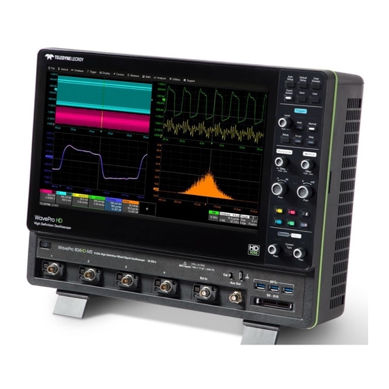
OVERVIEW Front of Oscilloscope A. Touch Screen Display B. Front Panel C. Power On/Off Button D. Calibration and Ground Terminals E. USB 3.1 Ports (3) F. Channel Inputs G. Ext In H. Aux Out I. Mixed Signal Interface J. Tilting Feet 929412-00 Rev A... -
Page 7: Powering On/Off
Note: The BNC inputs are rated to 8 GHz but will require a precision We recommend unplugging the instrument if it will remain unused for a adapter (available from Teledyne LeCroy Service) to accept SMA cables. long period of time. -
Page 8: Back And Side Of Oscilloscope
OVERVIEW Back and Side of Oscilloscope A. Built-in Carrying Handle D. Kensington Lock G. Speaker Out and Mic In I. USB 3.1 Ports (4) B. Removable Solid State Drive E. Ref In and Ref Out Connectors H. Ethernet Ports (2) J. -
Page 9: Connecting To External Devices/Systems
OVERVIEW Connecting to External Devices/Systems Printer After start up, configure external connections using the menu options WavePro HD supports USB printers that are compatible with the Windows listed below. See the WavePro HD Oscilloscopes Operator’s Manual for more detailed instructions. OS installed on the oscilloscope. - Page 10 WavePro HD oscilloscopes are compatible with the included passive Each flying lead has a signal and a ground connection. A variety of ground probes and most Teledyne LeCroy ProBus and ProBus2 active probes extenders and flying ground leads are available for different probing that are rated for the oscilloscope’s bandwidth.
-
Page 11: Front Panel
OVERVIEW Front Panel Most of the front panel controls duplicate functionality available through the touch screen display. They are covered in more detail in the Basics section and in the WavePro HD Oscilloscopes Operator’s Manual. Shortcut buttons arranged across the top of the front panel give quick access to commonly used functions. -
Page 12: Touch Screen Display
OVERVIEW Touch Screen Display The entire display is a capacitive touch screen. Use your finger or a capacitive stylus (not included) to touch, double-touch, touch-and-drag, or draw a selection box. Many controls that display information also work as “buttons” to access other functions. If you have a mouse installed, you can click anywhere you can touch to activate a control;... - Page 13 OVERVIEW A menu bar of drop-down menus lets you access all functionality. The Action toolbar on the main Channel, Math and Memory dialogs offers shortcuts to common actions so you don’t have to leave the underlying If an action can be “undone” (such as recalling a setup), a small dialog.
-
Page 14: Basics
BASICS Changing the Display Grid Mode The grid is 8 Vertical divisions representing 4096 Vertical levels and 10 By default, the oscilloscope has the Auto grid mode enabled. Auto adds a Horizontal time divisions. The value represented by each division depends grid for each new trace, up to 20 grids, until no more grids are available. - Page 15 BASICS Line, Intensity, and Persistence With the trace selected (and cursors The trace style can be set to a series of separate sample Points or a off), turn the front panel Adjust knobs to continuous vector Line. control the Trace Intensity. Grid Intensity makes the graticule dimmer or brighter relative to the trace.
-
Page 16: Working With Traces
BASICS Working with Traces Trace Descriptor Boxes Adjusting Channel (C1-C4), Zoom (Z1-Z12), Math (F1-F12), Memory (M1-M12), On setup dialogs, many entries can be made by selecting from the pop-up and Digital (Digital1-Digital4) descriptor boxes appear along the bottom menu that appears when you touch a control. of the grid area when a trace is turned on. -
Page 17: Maui With Onetouch
MAUI with OneTouch Touch, drag, swipe, pinch and flick can be used to create and change setups with one touch. Just as you change the display by using the setup dialogs, you can change the setups by moving different display objects. Use the setup dialogs to refine OneTouch gestures to precise values. As you drag-and-drop, valid targets are outlined with a white box. - Page 18 Copy Setups Change Source To copy the setup of one trace to another of the same type (e.g., channel to To change the source of a math, zoom or memory trace, drag-and-drop the channel, math to math), drag-and-drop the source descriptor box onto the descriptor box of the desired source onto the target descriptor box.
- Page 19 Position Cursors Change Trigger To change cursor measurement time/level, drag cursor markers to new To change the trigger level, drag the Trigger Level indicator to a new position positions on the grid. The cursor readout will update immediately. on the Y axis. The Trigger descriptor box will show the new Level. To place horizontal cursors on zooms or other calculated traces where the Horizontal Scale has forced cursors off the grid, drag the cursor readout from below the Timebase descriptor to the grid where you wish to place the...
- Page 20 Store to Memory Scroll To store a trace to internal memory, drag-and-drop its trace descriptor box To scroll long lists of values or readout tables, swipe the selection dialog or onto the target memory (Mn) descriptor box. table in an up or down direction. Move Trace To move a trace to a different grid, drag-and-drop the trace descriptor box onto the target grid.
- Page 21 Zoom Turn Off To create a new zoom trace, touch then drag To turn off a trace, flick the trace descriptor box toward the bottom of diagonally to draw a selection box around the the screen. portion of the trace you want to zoom. Touch the Zn descriptor box to open the zoom factor controls and adjust the zoom exactly.
-
Page 22: Vertical
BASICS Vertical Vertical controls adjust analog traces along the Y axis. Traces represent eight Vertical divisions of the source signal at the selected number of Volts or Amperes per division. The zero level is at the center grid line unless you add positive or negative Offset. The front panel Volts knob also controls the Vertical Scale of zoom, math and memory traces. - Page 23 BASICS From the Touch Screen Touch Channel descriptor once to reactivate the trace, twice to reopen the Cn dialog. Enter Attenuation for third-party probes. Refine Volts/div or Offset. Enter Enter signal Optionally, change Make other Pre-processing settings. Coupling Bandwidth. Vertical Unit of grid Note: Averaging, Interpolation and or Rescale trace.
-
Page 24: Digital
BASICS Digital On Mixed Signal instruments, Digital selections are added to the Vertical menu, and the front panel Vertical knobs control active Digital line and bus traces. From the Front Panel Digital Descriptor Box Turn Offset to # Digital Lines in Group raise/lower group Digital Sample Rate Vertical Position,... - Page 25 BASICS From the Touch Screen On the Logic Setup tab, choose a standard Touch Digital descriptor Logic Family, or enter a custom Threshold once to activate digital trace, and Hysteresis. Separate controls allow you twice to open Digitaln dialog. to set different values for each lead bank. Choose a Display Mode of individual digital lines, bus trace or both.
-
Page 26: Horizontal (Timebase)
BASICS BASICS Horizontal (Timebase) Horizontal controls adjust traces along the X axis. Analog traces usually represent one acquisition of the source signal for 10 divisions of the selected Time per division. The trigger event is shown at the center of the grid, unless you add positive or negative Delay time, which shifts the triger point left or right. The front panel Time/div knob also controls the Horizontal Scale of zoom, math and memory traces, allowing you to "zoom in"... - Page 27 BASICS From the Touch Screen Touch Timebase descriptor to open Timebase dialog. Select Sampling Refine Time/div Memory, sample Set Maximum Memory Use 4 standard or Change Time/div in and Delay. rate, and acquisition possible at Time/div, 2 interleaved channels reference to Center Mode.
-
Page 28: Navigating Long Acquisitions
BASICS Navigating Long Acquisitions For signal acquisitions >500 Mpts, measurements and math calculations take place on only the center 500 Mpts—the "Analysis Zone". This area is marked on the source channel trace by grey shading applied outside of it (over the part not analyzed). You may need to reposition the trace so that the portion you wish to analyze falls within the Analysis Zone. - Page 29 BASICS Navigating with Zoom Stop acquisition, then create a zoom trace of the area you wish to analyze. Apply math and measurements to the zoom rather than the channel trace. Math applied to a zoom is calculated on the entire trace (up to 500 Mpts). Highlighting on the source trace shows the zoomed area being analyzed.
- Page 30 BASICS Navigation Reference Changing the Navigation Reference setting can also help to reposition the acquired trace for analysis by selecting for different regions of the trace to remain centered as the Time/div changes: Centered (50%) scales divisions equally so that whatever is at the center (50%) grid line remains at the center of the display. Other events move in reference to the center as Time/div changes.
- Page 31 BASICS A Navigation Reference of Lock to Trigger rescales divisions around the trigger point. The trigger event remains in place as Time/div changes, while other events move in reference to the trigger. If the trigger is currently placed at time zero, this will appear to behave the same as Centered, but the difference will be apparent if you have used Delay to shift the trigger position.
-
Page 32: Triggers
BASICS Triggers Triggers tell the oscilloscope when to perform an acquisition. The acquisition starts as soon as the trigger is armed and all trigger conditions are met, unless postponed by a Holdoff count of time or number of trigger events. Trigger types and modes are described at more length in the WavePro HD Oscilloscopes Operator’s Manual. - Page 33 BASICS From the Touch Screen Touch Trigger descriptor to open Trigger dialog. Choose trigger Set trigger Levels, Source channel. or Find Levels based on the input signal mean. Choose trigger Type. Holdoff tab will appear when Edge or Pattern type Set other conditions, Icon summarizes the is selected.
-
Page 34: Zoom
BASICS Zoom Zoom traces display a magnified portion of another trace. Any trace can be zoomed, although Zoom is most useful for channel traces, as it allows you to see the source at the original Timebase at the same time as the Zoom "close up." Zoom is also useful for analyzing regions of >500 Mpts acquisitions that fall outside the center Analysis Zone. - Page 35 BASICS From the Touch Screen Zoom descriptor opens Zoom dialog Draw a Zoom box over a to make other portion of the source trace. adjustments. Repeat on another section to reposition the Zoom trace. On the source trace setup dialog, touch Action Toolbar Zoom button to create a new zoom of just that source trace.
-
Page 36: Cursors
BASICS Cursors Cursors set measurement points on the Vertical or Horizontal axis of a trace (or both). The five preset cursor types are described in more detail in the WavePro HD Oscilloscopes Operator’s Manual. From the Front Panel Adjust cursor position. Apply cursor. -
Page 37: Measurements & Statistics
BASICS Measurements & Statistics Measurements are waveform parameters that can be expressed as numerical values, such as amplitude or frequency. You can set up-to-12 simultaneous measurements and view the active readout in a table below the grid. Statistics can be displayed, along with histicons, a miniature histogram of the statistical distribution. -
Page 38: Math
BASICS Math Math creates a new trace that displays the result of applying a mathematical function (e.g., Sum, Product, FFT) to one or more source traces. One important distinction between math functions and measurement parameters is that the result of math is always another waveform, whereas the result of measurement is a number. -
Page 39: Memories (Reference Waveforms)
BASICS Memories (Reference Waveforms) Memories are traces stored for reference. They can be recalled to the display for comparison with other traces. A memory can be zoomed or measured for better analysis of historical data. You can store up-to-12 internal memories (M1-M12). After that, new memories will overwrite previously stored data. Internal memories persist only until the oscilloscope is rebooted. -
Page 40: Saving And Sharing Data
BASICS Saving and Sharing Data Setup, Waveform and Table Data Use the oscilloscope File menu options to save and recall data. See the WavePro HD Oscilloscopes Operator’s Manual for more information on using The current oscilloscope configuration can be saved to internal setup these features. -
Page 41: Maintenance
You will see a message on the oscilloscope that it is still warming up. Specifications are not guaranteed during the warm up period. To purchase an option (p.42), contact your Teledyne LeCroy sales representative. You will receive a license key via email that activates the Dynamic calibrations may occur during operation to maintain specified optional features on the oscilloscope. -
Page 42: Firmware Updates
MAINTENANCE Firmware Updates Switching Users Free firmware updates are available periodically from the Teledyne LeCroy The oscilloscope is by default set to operate from LeCroyUser, but you must website at teledynelecroy.com/support/softwaredownload. Registered run the oscilloscope from the Administrative User LCRYADMIN in order users will receive email notification when a new update is released. -
Page 43: Service
Service Centers COD or Collect shipments. We recommend air freighting. Insure the item For a complete list of Teledyne LeCroy offices by country, including our you’re returning for at least the replacement cost. Follow these steps for a sales and distribution partners, visit: teledynelecroy.com/support/contact smooth product return. -
Page 44: Reference
REFERENCE Software Options VectorLINQ (WPHD-VECTORLINQ) Vector Signal Analysis software These are just some of the software options available to enhance the options offer an extensive toolset for demodulation and analysis of RF operation of a WavePro HD oscilloscope. After activating your license key and IQ modulated signals. -
Page 45: Warranty
The product is warranted for normal use and operation, within specifications, for a period of three years from shipment. Teledyne LeCroy will either repair or, at our option, replace any product returned to one of our authorized service centers within this period. -
Page 46: Certifications
1 To ensure compliance with all applicable EMC standards, use high-quality shielded interface cables. 2 Emissions which exceed the levels required by this standard may occur when the instrument is Teledyne LeCroy certifies compliance to the following standards as of the time of publication. Please see the EC Declaration of Conformity connected to a test object. - Page 47 For more information about proper disposal and recycling of your • Measuring Circuit Terminals: No rated measurement category. Teledyne LeCroy product, please visit teledynelecroy.com/recycle. Terminals not intended to be connected directly to the mains supply. RESTRICTION OF HAZARDOUS SUBSTANCES (RoHS) •...
- Page 48 929412-00 Rev A, May, 2018 © 2018 Teledyne LeCroy, Inc. All rights reserved.