Table of Contents

Related Manuals for York YZ MODEL A


Summary of Contents for York YZ MODEL A
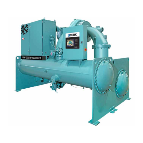
- Page 1 CENTRIFUGAL LIQUID CHILLERS WITH R-1233zd REFRIGERANT OPERATIONS AND MAINTENANCE NEW RELEASE Form 161.01-OM1 (618) 035-27132-100 YZ MODEL A MAGNETIC BEARING CENTRIFUGAL CHILLER WITH OPTIVIEW™ CONTROL CENTER Issue Date: June 8, 2018...
- Page 2 FORM 161.01-OM1 ISSUE DATE: 6/8/2018 IMPORTANT! READ BEFORE PROCEEDING! GENERAL SAFETY GUIDELINES This equipment is a relatively complicated apparatus. which it is situated, as well as severe personal injury or During rigging, installation, operation, maintenance, death to themselves and people at the site. or service, individuals may be exposed to certain com- This document is intended for use by owner-authorized ponents or conditions including, but not limited to:...
- Page 3 FORM 161.01-OM1 ISSUE DATE: 6/8/2018 CHANGEABILITY OF THIS DOCUMENT In complying with Johnson Controls’ policy for contin- these documents, the technician should verify whether uous product improvement, the information contained the equipment has been modified and if current litera- in this document is subject to change without notice. ture is available from the owner of the equipment prior Johnson Controls makes no commitment to update or to performing any work on the chiller.
- Page 4 FORM 161.01-OM1 ISSUE DATE: 6/8/2018 SYSTEM NOMENCLATURE YZ - MA033 AN030 P042N A Product Family Special Contract Motor End Name Unit Mod Level VSD Name Stage End Name MOTOR END NAMING Bearing Family Bearing Configuration Motor Configuration Motor HP Code Motor Family STAGE END NAMING A N 030 N...
- Page 5 FORM 161.01-OM1 ISSUE DATE: 6/8/2018 EVAPORATOR NAMING F A 21 12 ─ Z 750 ─ 2 Evap Number of Passes Evap Family 1, 2, 3 Pass Evap Mod Level Evap Tube Type Evap Diameter (Inches) Evap Bundle Fill Evap Length (Feet) Evap Bundle Code Evap Pass Limit 2 , 3 Pass...
-
Page 6: Table Of Contents
FORM 161.01-OM1 ISSUE DATE: 6/8/2018 TABLE OF CONTENTS SECTION 1 - SYSTEM FUNDAMENTALS ......................11 System Components ............................11 System Operation ............................15 Water Circuits ..............................17 SECTION 2 - SYSTEM OPERATING PROCEDURES ...................21 Pre-Starting ..............................21 Start-Up ................................21 Chiller Operation ............................ - Page 7 FORM 161.01-OM1 ISSUE DATE: 6/8/2018 TABLE OF CONTENTS (CONT'D) SECTION 6 - PRINTING ............................129 Printing Overview ............................129 Downloading System Prints to a Laptop ...................... 129 SECTION 7 - DECOMMISSIONING, DISMANTLING, AND DISPOSAL ............. 139 Temperature ..............................140 APPENDIX - MATERIAL SAFETY DATA SHEETS ....................141 JOHNSON CONTROLS...
- Page 8 FORM 161.01-OM1 ISSUE DATE: 6/8/2018 LIST OF FIGURES FIGURE 1 - YZ Chiller Components (Rear) ......................12 FIGURE 2 - YZ Chiller Components (Front) ......................12 FIGURE 3 - OptiView Control Center ........................13 FIGURE 4 - Refrigerant Flow-Thru Chiller.......................19 FIGURE 5 - Liquid Chiller Log Sheets ........................24 FIGURE 6 - Home Screen ............................30 FIGURE 7 - System Screen ............................32 FIGURE 8 - Evaporator Screen ..........................34...
- Page 9 FORM 161.01-OM1 ISSUE DATE: 6/8/2018 LIST OF FIGURES (CONT'D) FIGURE 55 - Sample Printout (Sales Order)......................135 FIGURE 56 - Sample Printout (Security Log Report) ....................136 FIGURE 57 - Sample Printout (Trend Data New or Existing Points) ..............137 FIGURE 58 - Sample Printout (Custom Screen Report) ..................137 LIST OF TABLES TABLE 1 - Input Current Limit Threshold ........................22 TABLE 2 - Temperature Setpoint ..........................23...
- Page 10 FORM 161.01-OM1 ISSUE DATE: 6/8/2018 THIS PAGE INTENTIONALLY LEFT BLANK. JOHNSON CONTROLS...
-
Page 11: Section 1 - System Fundamentals
SYSTEM COMPONENTS Condenser The condenser is a shell and tube type heat exchanger. The YORK Model YZ Centrifugal Chiller is complete- It has a discharge gas baffle to prevent direct high ve- ly factory-packaged. The package includes the evapo- locity impingement on the tubes. A separate subcooler rator, condenser, compressor, motor, variable speed is located in the condenser to enhance performance. -
Page 12: Figure 1 - Yz Chiller Components (Rear)
FORM 161.01-OM1 SECTION 1 - SYSTEM FUNDAMENTALS ISSUE DATE: 6/8/2018 Magnetic Bearing Motor Suction Line Purge Compact Waterboxes Evaporator LD22373 FIGURE 1 - YZ CHILLER COMPONENTS (REAR) Variable Optiview™ Speed Drive Control Panel Condenser Liquid Line Sight Liquid Level Glass Sensor LD22514 FIGURE 2 - YZ CHILLER COMPONENTS (FRONT) -
Page 13: Figure 3 - Optiview Control Center
Variable Speed Drive OptiView Control Center The Variable Speed Drive is factory packaged with The YORK OptiView™ control center LCD graphic the chiller. It is designed to vary the compressor motor display and keypad is the interface for starting, stop-... - Page 14 SC-EQUIP provides If the chiller is stopped and the condenser pump con- Johnson Controls and YORK mechanical equipment tacts are open (flow off), the contacts close when satu- such as the YZ chiller with building automation system rated condenser temperature is less than 35.0 °F (1.67...
-
Page 15: System Operation
FORM 161.01-OM1 SECTION 1 - SYSTEM FUNDAMENTALS ISSUE DATE: 6/8/2018 • Y – Commercial Chiller 03630 Microboard The speed at which the compressor rotates establishes the pressure differential that the chiller can operate • OPT - OptiView against. This is referred to as ‘lift’. Speed must always be maintained above the minimum necessary to create •... - Page 16 FORM 161.01-OM1 SECTION 1 - SYSTEM FUNDAMENTALS ISSUE DATE: 6/8/2018 • Conditions require capacity increase: Surge events are detected by monitoring the relation- ship between the Condenser pressure and Evaporator 1. HGBP (if present) is driven toward closed. pressure while the chiller is running. An excess surge condition is detected by comparing the number of 2.
-
Page 17: Water Circuits
FORM 161.01-OM1 SECTION 1 - SYSTEM FUNDAMENTALS ISSUE DATE: 6/8/2018 WATER CIRCUITS Flow Rate the condenser and evaporator must be analyzed by a For normal water chilling duty, the flow rates are per- water treatment specialist for practical and economical mitted at water velocity levels within the heat exchang- liquid chiller applications. - Page 18 FORM 161.01-OM1 SECTION 1 - SYSTEM FUNDAMENTALS ISSUE DATE: 6/8/2018 Connections Condenser Water The standard YZ chiller unit is designed for 1034 The chiller is engineered for maximum efficiency at kPa (150 PSIG) working pressure in both, chilled both design and part load operation by taking advan- water circuits and condenser water circuits.
-
Page 19: Figure 4 - Refrigerant Flow-Thru Chiller
FORM 161.01-OM1 SECTION 1 - SYSTEM FUNDAMENTALS ISSUE DATE: 6/8/2018 REFRIGERANT STATES Compressor Optional Hot Gas By- High Pressure Vapor pass Valve High Pressure Liquid Refrigerant Suction Line Evaporator Low Pressure Liquid Refrigerant Falling Film Hood Low Pressure Vapor Liquid Line Sub-Cooler Condenser Optional Isolation Valve... - Page 20 FORM 161.01-OM1 SECTION 1 - SYSTEM FUNDAMENTALS ISSUE DATE: 6/8/2018 THIS PAGE INTENTIONALLY LEFT BLANK. JOHNSON CONTROLS...
-
Page 21: Section 2 - System Operating Procedures
Condenser Water Temperature Control fail-closed, and set for a temperature The YORK YZ chiller is designed to lower power con- above dewpoint. It can be requested as sumption by taking advantage of lower than design factory-supplied by special quotation. -
Page 22: Chiller Operation
FORM 161.01-OM1 SECTION 2 - SYSTEM OPERATING PROCEDURES ISSUE DATE: 6/8/2018 The chiller will start if the following conditions are CHILLED LIQUID CONTROL SETTINGS met: Temperature Control Setpoint • Leaving Chilled Liquid Temperature is above the The temperature to which the chiller will control the setpoint chilled fluid leaving the evaporator must be set by the operator. -
Page 23: Operator Setpoints Quick Reference
FORM 161.01-OM1 SECTION 2 - SYSTEM OPERATING PROCEDURES ISSUE DATE: 6/8/2018 TABLE 2 - TEMPERATURE SETPOINT CONTROL LEAVING CHILLED LIQUID TEMPERATURE SETPOINT SOURCE Local Leaving Chilled Liquid Temperature Setpoint, entered from the panel. It is programmable over Local the range of 36.0°F to 72.0°F (2.2°C to 22.2 °C) (water) or 10.0°F to 72.0°F (-12.2 °C to 22.2 °C) (brine). -
Page 24: Stopping The System
FORM 161.01-OM1 SECTION 2 - SYSTEM OPERATING PROCEDURES ISSUE DATE: 6/8/2018 STOPPING THE SYSTEM SAFETY STOP There are three ways to stop the chiller. When depressed, the chiller will not run under any condition. For safety reasons, this position is required 1. -
Page 25: Fault Shutdowns
FORM 161.01-OM1 SECTION 2 - SYSTEM OPERATING PROCEDURES ISSUE DATE: 6/8/2018 For example, an increase in condenser approach tem- 3. If freezing temperatures could be encountered perature (condenser temperature minus leaving con- while the system is idle, drain the cooling water denser water temperature) may be an indication of from the cooling tower, condenser and condenser dirty condenser tubes. - Page 26 FORM 161.01-OM1 SECTION 2 - SYSTEM OPERATING PROCEDURES ISSUE DATE: 6/8/2018 THIS PAGE INTENTIONALLY LEFT BLANK. JOHNSON CONTROLS...
-
Page 27: Section 3 - Optiview™ Control Center Functions And Navigation
FORM 161.01-OM1 ISSUE DATE: 6/8/2018 SECTION 3 - OPTIVIEW™ CONTROL CENTER FUNCTIONS AND NAVIGATION INTERFACE CONVENTIONS • OPERATOR: The second access level is termed Each screen description in this document will begin OPERATOR and will allow the customer to with a section describing the graphical elements on change all of the setpoints required to operate the screen along with a short summary of the functions the chiller system. - Page 28 FORM 161.01-OM1 SECTION 3 - OPTIVIEW™ CONTROL CENTER FUNCTIONS AND NAVIGATION ISSUE DATE: 6/8/2018 Regardless of which setpoint is being programmed, the Navigation following procedure applies: In order to maximize the number of values which the panel can display to the user, and to place those values 1.
-
Page 29: Languages
FORM 161.01-OM1 SECTION 3 - OPTIVIEW™ CONTROL CENTER FUNCTIONS AND NAVIGATION ISSUE DATE: 6/8/2018 LANGUAGES ANALOG INPUT RANGES The screens can be displayed in various languages. The following table indicates the valid display range Language selection is done on the user screen. The de- for each of the analog input values. -
Page 30: Figure 6 - Home Screen
FORM 161.01-OM1 SECTION 3 - OPTIVIEW™ CONTROL CENTER FUNCTIONS AND NAVIGATION ISSUE DATE: 6/8/2018 LD26728 FIGURE 6 - HOME SCREEN When the chiller system is powered on, the above de- indicates chilled liquid flow and/or condenser cooling fault display appears. The Home Screen display depicts liquid flow when the flow switch inputs are satisfied. - Page 31 FORM 161.01-OM1 SECTION 3 - OPTIVIEW™ CONTROL CENTER FUNCTIONS AND NAVIGATION ISSUE DATE: 6/8/2018 PROGRAMMABLE BUTTON ACCESS LEVEL DESCRIPTION Use this key to generate a hard-copy report of the present system status. This provides a snapshot of the primary operating conditions at the time the key is Print VIEW pressed.
-
Page 32: Figure 7 - System Screen
FORM 161.01-OM1 SECTION 3 - OPTIVIEW™ CONTROL CENTER FUNCTIONS AND NAVIGATION ISSUE DATE: 6/8/2018 LD26729 FIGURE 7 - SYSTEM SCREEN The System Screen provides a general overview of common chiller parameters for both shells. DISPLAY ONLY FIELDS DISPLAY ONLY FIELDS FIELD/LED NAME DESCRIPTION Displays the temperature of the refrigerant in its gaseous state at discharge of... - Page 33 FORM 161.01-OM1 SECTION 3 - OPTIVIEW™ CONTROL CENTER FUNCTIONS AND NAVIGATION ISSUE DATE: 6/8/2018 DISPLAY ONLY FIELDS FIELD/LED NAME DESCRIPTION Displays the saturation temperature in the condenser calculated from condenser Condenser Saturation Temperature pressure. Evaporator Pressure Displays the present refrigerant pressure in the evaporator Displays the present saturation temperature in the evaporator calculated from Evaporator Saturation Temperature evaporator pressure.
-
Page 34: Figure 8 - Evaporator Screen
FORM 161.01-OM1 SECTION 3 - OPTIVIEW™ CONTROL CENTER FUNCTIONS AND NAVIGATION ISSUE DATE: 6/8/2018 LD26730 FIGURE 8 - EVAPORATOR SCREEN This screen displays a cutaway view of the chiller of the evaporation process indicates whether the chiller is presently in a RUN condition. Animation of the liq- evaporator. - Page 35 FORM 161.01-OM1 SECTION 3 - OPTIVIEW™ CONTROL CENTER FUNCTIONS AND NAVIGATION ISSUE DATE: 6/8/2018 DISPLAY ONLY FIELDS FIELD/LED NAME DESCRIPTION Leaving Chilled Liquid Temperature Displays the present value of the leaving chilled liquid temperature shutdown Setpoints (Shutdown) – Effective offset in effect limited by the chiller minimum temperature. Offset Leaving Chilled Liquid Temperature Displays the value set for leaving chilled liquid temperature restart offset.
-
Page 36: Figure 9 - Condenser Screen
FORM 161.01-OM1 SECTION 3 - OPTIVIEW™ CONTROL CENTER FUNCTIONS AND NAVIGATION ISSUE DATE: 6/8/2018 LD26731 FIGURE 9 - CONDENSER SCREEN This screen displays a cutaway view of the chiller con- dicates condenser liquid flow. This screen also serves denser. All setpoints relating to the condenser side of as a gateway to controlling the Refrigerant Level. - Page 37 FORM 161.01-OM1 SECTION 3 - OPTIVIEW™ CONTROL CENTER FUNCTIONS AND NAVIGATION ISSUE DATE: 6/8/2018 DISPLAY ONLY FIELDS FIELD/LED NAME DESCRIPTION Active Level Setpoint Displays the setpoint to which the refrigerant level is being controlled. Displays the position command to the level control valve in percent of travel with Level Control Valve Command 0% full closed to 100% full open.
-
Page 38: Figure 10 - Purge Screen
FORM 161.01-OM1 SECTION 3 - OPTIVIEW™ CONTROL CENTER FUNCTIONS AND NAVIGATION ISSUE DATE: 6/8/2018 LD26732 FIGURE 10 - PURGE SCREEN Low pressure systems such as the YZ chiller operate moves it. This screen displays a view of the purge sys- at pressures below atmospheric pressure. - Page 39 FORM 161.01-OM1 SECTION 3 - OPTIVIEW™ CONTROL CENTER FUNCTIONS AND NAVIGATION ISSUE DATE: 6/8/2018 DISPLAY ONLY FIELDS FIELD/LED NAME DESCRIPTION Purge Coil Temperature Displays the Purge Coil temperature. Displays the Condenser Saturation Temperature calculated from the Condenser Condenser Saturation Temperature Pressure.
-
Page 40: Figure 11 - Compressor Screen
FORM 161.01-OM1 SECTION 3 - OPTIVIEW™ CONTROL CENTER FUNCTIONS AND NAVIGATION ISSUE DATE: 6/8/2018 LD26733 FIGURE 11 - COMPRESSOR SCREEN This screen displays a cutaway view of the chiller com- presently in a RUN condition. This screen also serves pressor, revealing the impeller, and shows all condi- as a gateway to subscreens for jumping to capacity con- tions associated with the compressor. - Page 41 FORM 161.01-OM1 SECTION 3 - OPTIVIEW™ CONTROL CENTER FUNCTIONS AND NAVIGATION ISSUE DATE: 6/8/2018 NAVIGATION BUTTON DESCRIPTION Moves to the subscreen that allows viewing and programming of the Surge Surge Protection feature. Moves to the subscreen that allows viewing and calibrating the Variable Geom- etry Diffuser feature.
-
Page 42: Figure 12 - Capacity Control Screen
FORM 161.01-OM1 SECTION 3 - OPTIVIEW™ CONTROL CENTER FUNCTIONS AND NAVIGATION ISSUE DATE: 6/8/2018 LD26734 FIGURE 12 - CAPACITY CONTROL SCREEN This screen displays the pertinent parameters associat- anti-surge control. This screen also provides a means ed with capacity control in relation to Leaving Chilled for a Service Technician to control VGD, Speed, and Liquid temperature, current and pressure overrides, and Optional Hot Gas Bypass Valve manually for service. - Page 43 FORM 161.01-OM1 SECTION 3 - OPTIVIEW™ CONTROL CENTER FUNCTIONS AND NAVIGATION ISSUE DATE: 6/8/2018 DISPLAY ONLY FIELDS FIELD/LED NAME DESCRIPTION Displays the active temperature setpoint to which the chiller is set to control liq- uid leaving the evaporator. The Active Setpoint is a target to the Local, Remote or BAS (ISN) LCHLT programmed setpoint, depending on the control source selected.
- Page 44 FORM 161.01-OM1 SECTION 3 - OPTIVIEW™ CONTROL CENTER FUNCTIONS AND NAVIGATION ISSUE DATE: 6/8/2018 NAVIGATION NAVIGATION BUTTON DESCRIPTION Home Causes and instant return to the Home Screen. Compressor Causes an instant navigation to the Compressor Screen. Causes an instant navigation to the VSD Screen. JOHNSON CONTROLS...
-
Page 45: Figure 13 - Magnetic Bearing Controller (Mbc) Screen
FORM 161.01-OM1 SECTION 3 - OPTIVIEW™ CONTROL CENTER FUNCTIONS AND NAVIGATION ISSUE DATE: 6/8/2018 LD26735 FIGURE 13 - MAGNETIC BEARING CONTROLLER (MBC) SCREEN This screen displays the orientation of the magnetic on this screen. Many parameters are shown in the dia- bearing axes relative to the compressor driveline. - Page 46 FORM 161.01-OM1 SECTION 3 - OPTIVIEW™ CONTROL CENTER FUNCTIONS AND NAVIGATION ISSUE DATE: 6/8/2018 DISPLAY ONLY FIELDS FIELD/LED NAME DESCRIPTION Displays the Standard Deviation of the Radial Bearing J in the X and Y axis, Std Dev Thrust Bearing H and the Radial Bearing K in the X and Y axis expressed in Mils.
-
Page 47: Figure 14 - Surge Protection Screen
FORM 161.01-OM1 SECTION 3 - OPTIVIEW™ CONTROL CENTER FUNCTIONS AND NAVIGATION ISSUE DATE: 6/8/2018 LD26736 FIGURE 14 - SURGE PROTECTION SCREEN This screen displays the chiller compressor and all pa- The Surge Protection feature allows the user to define rameters relating to the Surge Protection feature. All how many surges are excessive and how the control setpoints relating to this screen are maintained on this will react to an excess surge condition. - Page 48 FORM 161.01-OM1 SECTION 3 - OPTIVIEW™ CONTROL CENTER FUNCTIONS AND NAVIGATION ISSUE DATE: 6/8/2018 PROGRAMMABLE PROGRAMMABLE BUTTON ACCESS LEVEL DESCRIPTION Shutdown Allows the user to select whether the chiller will shutdown or continue to run (Enabled/ Operator when an Excess Surge situation has been detected. Disabled) Extended Run Allows the user to select whether the chiller will shut-down or continue to run...
-
Page 49: Figure 15 - Variable Geometry Diffuser (Vgd) Screen
FORM 161.01-OM1 SECTION 3 - OPTIVIEW™ CONTROL CENTER FUNCTIONS AND NAVIGATION ISSUE DATE: 6/8/2018 LD26737 FIGURE 15 - VARIABLE GEOMETRY DIFFUSER (VGD) SCREEN This screen displays information pertinent to the VGD operation. DISPLAY ONLY FIELDS DISPLAY ONLY FIELDS FIELD/LED NAME DESCRIPTION Displays the Stall Detector output voltage (x.xxVdc), as received by the Stall Detector Voltage... -
Page 50: Figure 16 - Motor Details Screen
FORM 161.01-OM1 SECTION 3 - OPTIVIEW™ CONTROL CENTER FUNCTIONS AND NAVIGATION ISSUE DATE: 6/8/2018 LD26738 FIGURE 16 - MOTOR DETAILS SCREEN This screen displays information pertinent to the Motor perature. Also, individual winding temperature sensors Temperature Monitoring feature. The feature consists can be disabled on this screen of motor winding temperature and motor housing tem- DISPLAY ONLY FIELDS... - Page 51 FORM 161.01-OM1 SECTION 3 - OPTIVIEW™ CONTROL CENTER FUNCTIONS AND NAVIGATION ISSUE DATE: 6/8/2018 DISPLAY ONLY FIELDS FIELD/LED NAME DESCRIPTION When the optional Ambient Dew Point Temperature sensor is Enabled, its read- Ambient Dew Point Temperature ing is displayed here. Motor Cooling Valve Command Output to the motor cooling valve in percent from 0% (closed) to 100% Opened) Motor Cooling Control State...
-
Page 52: Figure 17 - Ups Screen
FORM 161.01-OM1 SECTION 3 - OPTIVIEW™ CONTROL CENTER FUNCTIONS AND NAVIGATION ISSUE DATE: 6/8/2018 LD26739 FIGURE 17 - UPS SCREEN This screen displays information pertaining to the un- interruptable power supply (UPS) and storage battery for essential loads necessary for shutdown during a line power loss. - Page 53 FORM 161.01-OM1 SECTION 3 - OPTIVIEW™ CONTROL CENTER FUNCTIONS AND NAVIGATION ISSUE DATE: 6/8/2018 UPS BATTERY MONITORING DISPLAY ONLY FIELDS FIELD/LED NAME DESCRIPTION Line Low Battery Voltage Offset, These are control setpoints for battery health fault logic. Inverter Low Battery Voltage Thresh- old, Line Low Battery Voltage Thresh- PROGRAMMABLE PROGRAMMABLE...
-
Page 54: Figure 18 - Motor - Variable Speed Drive (Vsd) Screen
FORM 161.01-OM1 SECTION 3 - OPTIVIEW™ CONTROL CENTER FUNCTIONS AND NAVIGATION ISSUE DATE: 6/8/2018 LD26740 FIGURE 18 - MOTOR - VARIABLE SPEED DRIVE (VSD) SCREEN This screen displays information pertaining to the Vari- able Speed Drive (VSD). DISPLAY ONLY FIELDS DISPLAY ONLY FIELDS FIELD/LED NAME DESCRIPTION... - Page 55 FORM 161.01-OM1 SECTION 3 - OPTIVIEW™ CONTROL CENTER FUNCTIONS AND NAVIGATION ISSUE DATE: 6/8/2018 HARMONIC FILTER DATA DISPLAY ONLY FIELDS FIELD/LED NAME DESCRIPTION Voltage Total Harmonic Distortion - Displays the Total Harmonic Distortion (THD) for each of the voltage lines as (L1, L2, L3) calculated by the VSD.
-
Page 56: Figure 19 - Variable Speed Drive (Vsd) Details Screen
FORM 161.01-OM1 SECTION 3 - OPTIVIEW™ CONTROL CENTER FUNCTIONS AND NAVIGATION ISSUE DATE: 6/8/2018 LD26741 FIGURE 19 - VARIABLE SPEED DRIVE (VSD) DETAILS SCREEN This screen displays more detailed parameters associ- ated with the Variable Speed Drive. This screen also provides a means for a Service Technician to access setpoints for maintenance or service. - Page 57 FORM 161.01-OM1 SECTION 3 - OPTIVIEW™ CONTROL CENTER FUNCTIONS AND NAVIGATION ISSUE DATE: 6/8/2018 NAVIGATION NAVIGATION BUTTON DESCRIPTION Home Causes an instant return to the Home screen. Causes an instant return to the VSD screen JOHNSON CONTROLS...
-
Page 58: Figure 20 - Harmonic Filter Details Screen
FORM 161.01-OM1 SECTION 3 - OPTIVIEW™ CONTROL CENTER FUNCTIONS AND NAVIGATION ISSUE DATE: 6/8/2018 LD26727 FIGURE 20 - HARMONIC FILTER DETAILS SCREEN This screen displays more detailed parameters associ- ated with the Harmonic Filter. DISPLAY ONLY FIELDS DISPLAY ONLY FIELDS FIELD/LED NAME DESCRIPTION Motor Run (LED) - Page 59 FORM 161.01-OM1 SECTION 3 - OPTIVIEW™ CONTROL CENTER FUNCTIONS AND NAVIGATION ISSUE DATE: 6/8/2018 NAVIGATION NAVIGATION BUTTON DESCRIPTION Home Causes an instant return to the Home screen. Causes an instant return to the VSD screen JOHNSON CONTROLS...
-
Page 60: Figure 21 - Setpoints Screen
FORM 161.01-OM1 SECTION 3 - OPTIVIEW™ CONTROL CENTER FUNCTIONS AND NAVIGATION ISSUE DATE: 6/8/2018 LD26742 FIGURE 21 - SETPOINTS SCREEN This screen provides a convenient location for pro- gramming the most common setpoints involved in the chiller control. This screen also serves as a gateway to a subscreen for defining the setup of general system parameters. - Page 61 FORM 161.01-OM1 SECTION 3 - OPTIVIEW™ CONTROL CENTER FUNCTIONS AND NAVIGATION ISSUE DATE: 6/8/2018 PROGRAMMABLE BUTTON ACCESS LEVEL DESCRIPTION Allows the user to specify the current limit value (as a percentage of Full Load Amps) to which the chiller will be limited during the specified pulldown limit time. Pulldown This value will override the Input Current Limit value during this time period.
-
Page 62: Figure 22 - Setup Screen
FORM 161.01-OM1 SECTION 3 - OPTIVIEW™ CONTROL CENTER FUNCTIONS AND NAVIGATION ISSUE DATE: 6/8/2018 LD26743 FIGURE 22 - SETUP SCREEN This screen is the top level of the general configura- be displayed (12 or 24 hour format). This screen also tion parameters. - Page 63 FORM 161.01-OM1 SECTION 3 - OPTIVIEW™ CONTROL CENTER FUNCTIONS AND NAVIGATION ISSUE DATE: 6/8/2018 PROGRAMMABLE PROGRAMMABLE BUTTON ACCESS LEVEL DESCRIPTION Power Failure Allows the user to select Manual or Automatic restart after power failure. Operator Restart Allows the user to specify the present date. This value is critical to logging system shutdowns accurately and for utilizing the scheduling capabilities.
-
Page 64: Figure 23 - Schedule Screen
FORM 161.01-OM1 SECTION 3 - OPTIVIEW™ CONTROL CENTER FUNCTIONS AND NAVIGATION ISSUE DATE: 6/8/2018 LD26744 FIGURE 23 - SCHEDULE SCREEN The schedule screen contains more programmable val- through several days, the Stop time of Day 1 can be ues than a normal display screen. As such, each pro- set to 11:59 PM and the Start time of Day 2 can be set grammable value is not linked to a specific button. - Page 65 FORM 161.01-OM1 SECTION 3 - OPTIVIEW™ CONTROL CENTER FUNCTIONS AND NAVIGATION ISSUE DATE: 6/8/2018 PROGRAMMABLE PROGRAMMABLE BUTTON ACCESS LEVEL DESCRIPTION Standard Week For each day of the week, the user may specify a time for the chiller to start and Start/Stop Operator a time for the chiller to stop.
-
Page 66: Figure 24 - User Screen
FORM 161.01-OM1 SECTION 3 - OPTIVIEW™ CONTROL CENTER FUNCTIONS AND NAVIGATION ISSUE DATE: 6/8/2018 LD26745 FIGURE 24 - USER SCREEN This screen allows definition of custom User ID’s and Each Custom User value is not linked to a specific matching passwords. This allows the building admin- button. -
Page 67: Figure 25 - Comms Screen
FORM 161.01-OM1 SECTION 3 - OPTIVIEW™ CONTROL CENTER FUNCTIONS AND NAVIGATION ISSUE DATE: 6/8/2018 LD26746 FIGURE 25 - COMMS SCREEN This screen allows definition of the necessary commu- setup. COM 2 communications features are automati- nications parameters. See SECTION 6 - PRINTING of cally set and can not be adjusted. -
Page 68: Figure 26 - Printer Screen
FORM 161.01-OM1 SECTION 3 - OPTIVIEW™ CONTROL CENTER FUNCTIONS AND NAVIGATION ISSUE DATE: 6/8/2018 LD26747 FIGURE 26 - PRINTER SCREEN This screen allows definition of the desired printer type and print interval. DISPLAY ONLY FIELDS DISPLAY ONLY FIELDS FIELD/LED NAME DESCRIPTION Time Remaining Until Next Print Displays the time until the next print log will occur, if the function is enabled. - Page 69 FORM 161.01-OM1 SECTION 3 - OPTIVIEW™ CONTROL CENTER FUNCTIONS AND NAVIGATION ISSUE DATE: 6/8/2018 NAVIGATION NAVIGATION BUTTON DESCRIPTION Home Causes an instant return to the Home Screen. Setup Return to the previous Setup Screen. JOHNSON CONTROLS...
-
Page 70: Figure 27 - Sales Order Screen
Service Tech- Controls Service Technician at the time of chiller com- nician. The remainder of the values are entered at the YORK Factory during the manufacturing of the chiller. DISPLAY ONLY FIELDS DISPLAY ONLY FIELDS... - Page 71 FORM 161.01-OM1 SECTION 3 - OPTIVIEW™ CONTROL CENTER FUNCTIONS AND NAVIGATION ISSUE DATE: 6/8/2018 DISPLAY ONLY FIELDS FIELD/LED NAME DESCRIPTION Volts Factory defined motor line Voltage. Phases Factory defined number of line Phases. Frequency Factory defined line Frequency. Factory defined motor Locked Rotor Amps. Full Load Amps Factory defined motor Full Load Amps.
-
Page 72: Figure 28 - Operations Screen
FORM 161.01-OM1 SECTION 3 - OPTIVIEW™ CONTROL CENTER FUNCTIONS AND NAVIGATION ISSUE DATE: 6/8/2018 LD26749 FIGURE 28 - OPERATIONS SCREEN This screen allows definition of general parameters having to do with the operation of the chiller. This screen also display the Johnson Control Service tele- phone number. -
Page 73: Figure 29 - Remote Control Screen
FORM 161.01-OM1 SECTION 3 - OPTIVIEW™ CONTROL CENTER FUNCTIONS AND NAVIGATION ISSUE DATE: 6/8/2018 LD26750 FIGURE 29 - REMOTE CONTROL SCREEN This screen allows the user to independently select the • In Local mode the chiller will control to the Local method of control for Run/Stop, Cooling Setpoint and Setpoint. -
Page 74: Figure 30 - History Screen
FORM 161.01-OM1 SECTION 3 - OPTIVIEW™ CONTROL CENTER FUNCTIONS AND NAVIGATION ISSUE DATE: 6/8/2018 LD26751 FIGURE 30 - HISTORY SCREEN This screen allows the user to browse through the faults. is used to jump to a subscreen containing stored chiller In order to get a more thorough reporting of the system parameters values at the time of the shutdown. - Page 75 FORM 161.01-OM1 SECTION 3 - OPTIVIEW™ CONTROL CENTER FUNCTIONS AND NAVIGATION ISSUE DATE: 6/8/2018 PROGRAMMABLE BUTTON ACCESS LEVEL DESCRIPTION Page Down Operator Scrolls down 10 faults on the display. Causes a move to a subscreen containing the values of select chiller parameters View Details Operator at the time of the associated shutdown...
-
Page 76: Figure 31 - History Details Screen
FORM 161.01-OM1 SECTION 3 - OPTIVIEW™ CONTROL CENTER FUNCTIONS AND NAVIGATION ISSUE DATE: 6/8/2018 LD26752 FIGURE 31 - HISTORY DETAILS SCREEN This screen allows the user to see an on-screen printout ber of screens required to display all of the data varies of all the system parameters at the time of the selected according to type of motor starter and options applied. -
Page 77: Figure 32 - Custom Screen
FORM 161.01-OM1 SECTION 3 - OPTIVIEW™ CONTROL CENTER FUNCTIONS AND NAVIGATION ISSUE DATE: 6/8/2018 LD26753 FIGURE 32 - CUSTOM SCREEN This screen allows up to 10 Service Technician select- parameters pertinent to a particular problem during ed parameters to be displayed. These parameters are troubleshooting. -
Page 78: Figure 33 - Custom Setup Screen
FORM 161.01-OM1 SECTION 3 - OPTIVIEW™ CONTROL CENTER FUNCTIONS AND NAVIGATION ISSUE DATE: 6/8/2018 LD26754 FIGURE 33 - CUSTOM SETUP SCREEN This screen allows the Service technician to select up to 10 parameters for display on the Custom View Screen. DISPLAY ONLY FIELDS DISPLAY ONLY FIELDS FIELD/LED NAME... - Page 79 FORM 161.01-OM1 SECTION 3 - OPTIVIEW™ CONTROL CENTER FUNCTIONS AND NAVIGATION ISSUE DATE: 6/8/2018 NAVIGATION NAVIGATION BUTTON DESCRIPTION Home Causes an instant return to the Home Screen. Custom View Causes a return to the custom view screen. JOHNSON CONTROLS...
-
Page 80: Figure 34 - Trend Screen
FORM 161.01-OM1 SECTION 3 - OPTIVIEW™ CONTROL CENTER FUNCTIONS AND NAVIGATION ISSUE DATE: 6/8/2018 LD26755 FIGURE 34 - TREND SCREEN As many as six Operator selected parameters (data There are three types of charts that can be created: points) can be plotted in an X/Y graph format. The X- •... - Page 81 FORM 161.01-OM1 SECTION 3 - OPTIVIEW™ CONTROL CENTER FUNCTIONS AND NAVIGATION ISSUE DATE: 6/8/2018 A red screen displaying TREND MAX DISPLAY ONLY FIELDS MUST BE > TREND MIN will appear This screen allows the user to view the graphical trend- if the Y-Axis minimum has been pro- ing of the selected parameters and is also a gateway to grammed to a value that is greater than...
-
Page 82: Figure 35 - Trend Setup Screen
FORM 161.01-OM1 SECTION 3 - OPTIVIEW™ CONTROL CENTER FUNCTIONS AND NAVIGATION ISSUE DATE: 6/8/2018 LD26756 FIGURE 35 - TREND SETUP SCREEN This screen is used to configure the trending screen. 6. The Y-Axis minimum and maximum values for each The parameters to be trended are selected from the parameter are entered as Data Point Min and Data Common Slots Screen or Common Slots Master list Point Max for Data Points 1 through 6. - Page 83 FORM 161.01-OM1 SECTION 3 - OPTIVIEW™ CONTROL CENTER FUNCTIONS AND NAVIGATION ISSUE DATE: 6/8/2018 PROGRAMMABLE BUTTON ACCESS LEVEL DESCRIPTION This key is used to enter the slot numbers and the minimum and maximum Y-Axis values of each parameter to be trended. Pressing this key places a yel- low box around Data Point 1 Slot Number.
-
Page 84: Figure 36 - Advanced Trend Setup Screen
FORM 161.01-OM1 SECTION 3 - OPTIVIEW™ CONTROL CENTER FUNCTIONS AND NAVIGATION ISSUE DATE: 6/8/2018 LD26757 FIGURE 36 - ADVANCED TREND SETUP SCREEN The desired data collection start/stop triggers are setup A Secondary Trigger can be evaluated with the Prima- on this screen. The trend data collection can be set to ry Trigger to start/stop data collection. - Page 85 FORM 161.01-OM1 SECTION 3 - OPTIVIEW™ CONTROL CENTER FUNCTIONS AND NAVIGATION ISSUE DATE: 6/8/2018 PROGRAMMABLE PROGRAMMABLE BUTTON ACCESS LEVEL DESCRIPTION Selects the first parameter to be evaluated. Selection is made from the Slot Primary Trigger Operator Numbers listing on the Trend Common Slots Screen or the Master Slot Numbers List in this manual.
-
Page 86: Figure 37 - Common Slots Screen
FORM 161.01-OM1 SECTION 3 - OPTIVIEW™ CONTROL CENTER FUNCTIONS AND NAVIGATION ISSUE DATE: 6/8/2018 LD26758 FIGURE 37 - COMMON SLOTS SCREEN This screen displays the slot numbers of the commonly From these lists, select up to six parameters to be trend- monitored parameters. -
Page 87: Master Slot Numbers List For Use With Trend Feature
FORM 161.01-OM1 SECTION 3 - OPTIVIEW™ CONTROL CENTER FUNCTIONS AND NAVIGATION ISSUE DATE: 6/8/2018 MASTER SLOT NUMBERS LIST FOR USE WITH TREND FEATURE SLOT # DESCRIPTION SLOT # DESCRIPTION SYSTEM SURGE Chiller Operating State 8236 ACC Surge Detected Safety Relay 8238 Surge Avoidance Count Cycling Relay... - Page 88 FORM 161.01-OM1 SECTION 3 - OPTIVIEW™ CONTROL CENTER FUNCTIONS AND NAVIGATION ISSUE DATE: 6/8/2018 SLOT # DESCRIPTION SLOT # DESCRIPTION CAPACITY CONTROL 23844 MBC Motor Speed 18273 Control State 23849 MBC Heatsink Temperature 18280 Load Limit 23845 J Bearing Temperature 18122 VSD Frequency Command 23848...
- Page 89 FORM 161.01-OM1 SECTION 3 - OPTIVIEW™ CONTROL CENTER FUNCTIONS AND NAVIGATION ISSUE DATE: 6/8/2018 SLOT # DESCRIPTION 24354 Control Voltage 24353 Power Loss Time 24355 UPS Line/Charging 24356 UPS Inverter 24357 UPS Fault 24360 UPS Battery Voltage 24358 UPS Inverter Enable PURGE 24322 Purge Control State...
-
Page 90: Display Messages
FORM 161.01-OM1 SECTION 3 - OPTIVIEW™ CONTROL CENTER FUNCTIONS AND NAVIGATION ISSUE DATE: 6/8/2018 DISPLAY MESSAGES The Status Bar of the Display contains a Status Line To aid in the meaning of the message, messages are and, beneath it a Details Line. The Status Line contains displayed in different colors as follows: a message describing the operating state of the chill- •... -
Page 91: Table 6 - Run Messages
FORM 161.01-OM1 SECTION 3 - OPTIVIEW™ CONTROL CENTER FUNCTIONS AND NAVIGATION ISSUE DATE: 6/8/2018 TABLE 6 - RUN MESSAGES MESSAGE DESCRIPTION LEAVING CHILLED LIQUID The chiller is running, controlling the Leaving Chilled Liquid to the Leaving Chilled Liquid CONTROL Temperature Setpoint. No system conditions is inhibiting this operation. This non-annunciating message alerts that the DC Bus is precharged or pre-regulated for a state outside of chiller run. -
Page 92: Table 9 - Warning Messages
FORM 161.01-OM1 SECTION 3 - OPTIVIEW™ CONTROL CENTER FUNCTIONS AND NAVIGATION ISSUE DATE: 6/8/2018 TABLE 9 - WARNING MESSAGES MESSAGE DESCRIPTION While the chiller state is Stopped, the Saturated Condenser Temperature decreased WARNING - CONDENSER below 35.0 °F (1.7 °C). The condenser pump run contacts close. The message is auto- FREEZE THREAT FROM LOW matically reset and pump contacts return to prior state when either the chiller is not in PRESSURE... - Page 93 FORM 161.01-OM1 SECTION 3 - OPTIVIEW™ CONTROL CENTER FUNCTIONS AND NAVIGATION ISSUE DATE: 6/8/2018 TABLE 9 - WARNING MESSAGES MESSAGE DESCRIPTION The chiller motor current is greater than or equal to the Motor Overload current limit. The Motor Overload current limit is predetermined from the motor model and Maximum WARNING –...
-
Page 94: Table 10 - Routine Shutdown Messages
FORM 161.01-OM1 SECTION 3 - OPTIVIEW™ CONTROL CENTER FUNCTIONS AND NAVIGATION ISSUE DATE: 6/8/2018 TABLE 9 - WARNING MESSAGES (CONT'D) MESSAGE DESCRIPTION This auto reset warning is set when all of the following are true for 5 continuous sec- onds: WARNING –... -
Page 95: Table 11 - Cycling Shutdown Messages
FORM 161.01-OM1 SECTION 3 - OPTIVIEW™ CONTROL CENTER FUNCTIONS AND NAVIGATION ISSUE DATE: 6/8/2018 TABLE 11 - CYCLING SHUTDOWN MESSAGES The chiller will automatically restart when the cycling condition clears. MESSAGE DESCRIPTION The Chilled Liquid Flow Switch has remained open for 5 continuous seconds while the CHILLED LIQUID –... - Page 96 FORM 161.01-OM1 SECTION 3 - OPTIVIEW™ CONTROL CENTER FUNCTIONS AND NAVIGATION ISSUE DATE: 6/8/2018 TABLE 11 - CYCLING SHUTDOWN MESSAGES (CONT'D) MESSAGE DESCRIPTION The optional brine freeze protection motorized isolation valves Close output is ener- ISOLATION VALVES - NOT gized > 40 seconds but the feedback from the valve limit switch does not indicate it CLOSED closed for 3 continuous seconds.
- Page 97 FORM 161.01-OM1 SECTION 3 - OPTIVIEW™ CONTROL CENTER FUNCTIONS AND NAVIGATION ISSUE DATE: 6/8/2018 TABLE 11 - CYCLING SHUTDOWN MESSAGES (CONT'D) MESSAGE DESCRIPTION The DC bus voltage is continuously monitored and a shutdown will occur if the DC bus VSD – HIGH DC BUS VOLTAGE voltage exceeds 737-795 VDC.
- Page 98 FORM 161.01-OM1 SECTION 3 - OPTIVIEW™ CONTROL CENTER FUNCTIONS AND NAVIGATION ISSUE DATE: 6/8/2018 TABLE 11 - CYCLING SHUTDOWN MESSAGES (CONT'D) MESSAGE DESCRIPTION During Pre-charge, the dc-link voltage must reach at least low threshold which is determined by Line Voltage Setpoint (see the table below) within 4 seconds after the pre-charge signal has been commanded.
- Page 99 FORM 161.01-OM1 SECTION 3 - OPTIVIEW™ CONTROL CENTER FUNCTIONS AND NAVIGATION ISSUE DATE: 6/8/2018 TABLE 11 - CYCLING SHUTDOWN MESSAGES (CONT'D) MESSAGE DESCRIPTION The three phases of RMS filter current are measured by the filter DCCTs’. This informa- tion is sent to the harmonic filter logic board. If any one phase of filter current exceeds a threshold for 40 seconds a shutdown will occur.
- Page 100 FORM 161.01-OM1 SECTION 3 - OPTIVIEW™ CONTROL CENTER FUNCTIONS AND NAVIGATION ISSUE DATE: 6/8/2018 TABLE 11 - CYCLING SHUTDOWN MESSAGES (CONT'D) MESSAGE DESCRIPTION The harmonic filter dynamically generates its own filter DC bus voltage by the interac- tion of the harmonic filter inductor and switching the power devices in the harmonic filter power unit.
-
Page 101: Table 12 - Safety Shutdown Messages
For Brine cooling applications, the shutdown threshold varies according to the concentration of the Brine solution. The Brine shutdown thresh- old is programmed at the YORK Factory. The chiller can be started after the evaporator pressure EVAPORATOR – LOW increases to the restart threshold and the CLEAR FAULT key is pressed. - Page 102 FORM 161.01-OM1 SECTION 3 - OPTIVIEW™ CONTROL CENTER FUNCTIONS AND NAVIGATION ISSUE DATE: 6/8/2018 TABLE 12 - SAFETY SHUTDOWN MESSAGES (CONT'D) MESSAGE DESCRIPTION The optional brine freeze protection motorized isolation valves Open output is energized 40 seconds but the feedback from the valve limit switch does not indicate it opened for 3 continu- ISOLATION VALVES - ous seconds.
- Page 103 FORM 161.01-OM1 SECTION 3 - OPTIVIEW™ CONTROL CENTER FUNCTIONS AND NAVIGATION ISSUE DATE: 6/8/2018 TABLE 12 - SAFETY SHUTDOWN MESSAGES (CONT'D) MESSAGE DESCRIPTION This Safety Shutdown is set when OptiView software is commanding MBC Levitation Mode ON but the MBC is not reporting Levitated within 15 seconds. This fault is prohibited when the MBC MBC –...
- Page 104 FORM 161.01-OM1 SECTION 3 - OPTIVIEW™ CONTROL CENTER FUNCTIONS AND NAVIGATION ISSUE DATE: 6/8/2018 TABLE 12 - SAFETY SHUTDOWN MESSAGES (CONT'D) MESSAGE DESCRIPTION This safety shutdown is set when the Model Number field entered on the Setpoints – Setup – Sales Order screen does not conform to the format expected.
- Page 105 FORM 161.01-OM1 SECTION 3 - OPTIVIEW™ CONTROL CENTER FUNCTIONS AND NAVIGATION ISSUE DATE: 6/8/2018 TABLE 12 - SAFETY SHUTDOWN MESSAGES (CONT'D) MESSAGE DESCRIPTION The drive logic board generates this shutdown by reading the current from the 3 output cur- rent transformers. The shutdown is generated when the drive logic board has detected that the VSD –...
- Page 106 FORM 161.01-OM1 SECTION 3 - OPTIVIEW™ CONTROL CENTER FUNCTIONS AND NAVIGATION ISSUE DATE: 6/8/2018 TABLE 12 - SAFETY SHUTDOWN MESSAGES (CONT'D) MESSAGE DESCRIPTION The control center determines this shutdown by using data supplied from the harmonic filter logic board. This shutdown indicates that the filter is not operating correctly or the input current to Harmonic Filter –...
-
Page 107: Section 4 - Vsd Operation
SECTION 4 - VSD OPERATION PYT MODEL VSD OVERVIEW AC to DC Rectifier The YORK PYT model VSD is a liquid cooled, transis- torized, PWM inverter in a highly integrated package The AC to DC converter uses 3 Silicon Controlled mounted directly to the chiller. -
Page 108: Pyt Model Vsd (330, 420, 780, 1020 & 1280 Amp)
FORM 161.01-OM1 SECTION 4 - VSD OPERATION ISSUE DATE: 6/8/2018 DC to AC Converter PYT MODEL VSD (330, 420, 780, 1020 & 1280 AMP) The DC to AC inverter section of the VSD serves to convert the DC voltage to AC voltage at the proper All PYT model VSDs function in the same manner and magnitude and frequency, as commanded by the VSD have the same basic components. -
Page 109: Critical Load Power
FORM 161.01-OM1 SECTION 4 - VSD OPERATION ISSUE DATE: 6/8/2018 ter power unit is disconnected from the AC line. When Transistor Module the chiller begins to run, the pre-charge resistors are The transistor module contains a temperature sensor switched into the circuit via the precharge contactor for that provides temperature information back to the fil- a fixed time period of 5 seconds. -
Page 110: Figure 38 - Drive Cabinet Door (Pyt330, Pyt420, Pyt780 & Pyt1020)
FORM 161.01-OM1 SECTION 4 - VSD OPERATION ISSUE DATE: 6/8/2018 DRIVE LOGIC BOARD FILTER LOGIC BOARD LD26706 FIGURE 38 - DRIVE CABINET DOOR (PYT330, PYT420, PYT780 & PYT1020) DRIVE LOGIC BOARD FILTER LOGIC BOARD LD26707 FIGURE 39 - DRIVE CABINET DOOR (PYT1280) JOHNSON CONTROLS... -
Page 111: Figure 40 - Drive Cabinet Model Pyt330
FORM 161.01-OM1 SECTION 4 - VSD OPERATION ISSUE DATE: 6/8/2018 Main UPS UPS Battery Filter Power Unit Filter Inductor Input Inductor Circuit Breaker Filter Supply POWER Contactor UNIT Filter Trap Assembly Cooling Coil Cooling Fan 300VDC Magnetic Bearing Power Supply Rectifier Inverter LD26704... -
Page 112: Figure 42 - Left Side Of Drive Cabinet Model Pyt780
FORM 161.01-OM1 SECTION 4 - VSD OPERATION ISSUE DATE: 6/8/2018 Filter Inductor Input Inductor Circuit Breaker Filter Supply Contactor Filter Trap Assembly Cooling Coil Cooling Fan LD26709 FIGURE 42 - LEFT SIDE OF DRIVE CABINET MODEL PYT780 JOHNSON CONTROLS... -
Page 113: Figure 43 - Right Side Of Drive Cabinet Model Pyt780
FORM 161.01-OM1 SECTION 4 - VSD OPERATION ISSUE DATE: 6/8/2018 300VDC Magnetic Bearing Power Supply Main UPS UPS Battery (Behind Panel) Filter Power Unit Cooling Coil Cooling Fan Rectifier Inverter POWER UNIT LD26710 FIGURE 43 - RIGHT SIDE OF DRIVE CABINET MODEL PYT780 JOHNSON CONTROLS... -
Page 114: Figure 44 - Left Side Of Drive Cabinet Model Pyt1020
FORM 161.01-OM1 SECTION 4 - VSD OPERATION ISSUE DATE: 6/8/2018 Filter Supply Contactor Input Inductor Filter Inductor Harmonic Filter Circuit Breaker Cooling Coil Cooling Fan Rectifier Inverter POWER UNIT LD26716 FIGURE 44 - LEFT SIDE OF DRIVE CABINET MODEL PYT1020 JOHNSON CONTROLS... -
Page 115: Figure 45 - Right Side Of Drive Cabinet Model Pyt1020
FORM 161.01-OM1 SECTION 4 - VSD OPERATION ISSUE DATE: 6/8/2018 300VDC Magnetic Bearing Power Supply Main UPS Bus Capacitors UPS Battery (Behind Panel) Filter Power Unit Cooling Coil Cooling Fan LD26717 FIGURE 45 - RIGHT SIDE OF DRIVE CABINET MODEL PYT1020 JOHNSON CONTROLS... -
Page 116: Figure 46 - Left Side Of Drive Cabinet Model Pyt1280
FORM 161.01-OM1 SECTION 4 - VSD OPERATION ISSUE DATE: 6/8/2018 Filter Power Unit Filter Inductor Filter Supply Contactor Input Inductor Circuit Breaker Filter Trap Assembly Cooling Coil Cooling Fan LD26711 FIGURE 46 - LEFT SIDE OF DRIVE CABINET MODEL PYT1280 JOHNSON CONTROLS... -
Page 117: Figure 47 - Right Side Of Drive Cabinet Model Pyt1280
FORM 161.01-OM1 SECTION 4 - VSD OPERATION ISSUE DATE: 6/8/2018 300VDC Magnetic Bearing Power Supply UPS Battery (Behind Panel) Main UPS Cooling Coil Cooling Fan Rectifier Inverter POWER UNIT LD26712 FIGURE 47 - RIGHT SIDE OF DRIVE CABINET MODEL PYT1280 JOHNSON CONTROLS... - Page 118 FORM 161.01-OM1 SECTION 4 - VSD OPERATION ISSUE DATE: 6/8/2018 THIS PAGE INTENTIONALLY LEFT BLANK. JOHNSON CONTROLS...
-
Page 119: Section 5 - Maintenance
This procedure must be performed at the specified time interval by an Industry Certified Technician who has been trained and qualified to work on this type of YORK equipment. A record of this procedure being successfully carried out must be maintained on file by the equipment owner should proof of adequate maintenance be required at a later date for warranty validation purposes. -
Page 120: Renewal Parts
FORM 161.01-OM1 SECTION 5 - MAINTENANCE ISSUE DATE: 6/8/2018 RENEWAL PARTS Annually (More Often If Necessary) 1. Evaporator and Condenser Parts Navi- For any required Renewal Parts, refer to gator a. Inspect and clean water strainers b. Inspect and clean tubes as required OPERATING INSPECTIONS c. -
Page 121: System Evacuation
FORM 161.01-OM1 SECTION 5 - MAINTENANCE ISSUE DATE: 6/8/2018 4. To improve evacuation circulate hot water, not 4. Test around each joint and factory weld carefully to exceed 120 °F (49 ºC) through the evaporator and thoroughly. and condenser tubes to thoroughly dehydrate the 5. -
Page 122: Figure 48 - Evacuation Of Chiller
FORM 161.01-OM1 SECTION 5 - MAINTENANCE ISSUE DATE: 6/8/2018 TABLE 14 - SYSTEM PRESSURES *GAUGE ABSOLUTE BOILING INCHES OF MERCURY MILLIMETERS TEMPERATURES (HG) BELOW ONE PSIA OF MERCURY MICRONS OF WATER °F STANDARD (HG) ATMOSPHERE 0" 14.6960 760.00 760,000 10.240" 9.6290 500.00 500,000... -
Page 123: Figure 49 - Saturation Curve
FORM 161.01-OM1 SECTION 5 - MAINTENANCE ISSUE DATE: 6/8/2018 Operation Dehydration of a refrigerant system can be obtained by this method because the water present in the system reacts much as a refrigerant would. By pulling down the pressure in the system to a point where its satu- ration temperature is considerably below that of room temperature, heat will flow from the room through the walls of the system and vaporize the water, allowing... -
Page 124: Conduct Pressure Test
FORM 161.01-OM1 SECTION 5 - MAINTENANCE ISSUE DATE: 6/8/2018 CONDUCT PRESSURE TEST Refrigerant may be furnished in cylinders containing either 100 lbs or 1900 lbs. (45 kg or 862 kg) of refrig- If a pressure test indicates all joints are not leaking, erant. -
Page 125: Handling Refrigerant For Dismantling And Repairs
FORM 161.01-OM1 SECTION 5 - MAINTENANCE ISSUE DATE: 6/8/2018 HANDLING REFRIGERANT FOR COMPRESSOR AND MOTOR DISMANTLING AND REPAIRS 1. Check mounting screws and piping joint nuts fre- If it becomes necessary to open any part of the refriger- quently to insure tightness. ant system for repairs, it will be necessary to remove 2. - Page 126 FORM 161.01-OM1 SECTION 5 - MAINTENANCE ISSUE DATE: 6/8/2018 1. The condenser tubes should be cleaned annually Condenser or earlier if conditions warrant. If the temperature In a condenser, trouble due to fouled tubes is usually difference between the water off the condenser indicated by a steady rise in head pressure, over a pe- and the condenser liquid temperature is more than riod of time, accompanied by a steady rise in condens-...
-
Page 127: Electrical Controls
FORM 161.01-OM1 SECTION 5 - MAINTENANCE ISSUE DATE: 6/8/2018 from the tubes with the result that a more satisfactory 3. With nitrogen or dry air, blow out the tubes to cleaning job will be accomplished with a probable sav- clear them of traces of refrigerant laden moisture ing of time. -
Page 128: Automatic Battery Health Test - During Shutdown
FORM 161.01-OM1 SECTION 5 - MAINTENANCE ISSUE DATE: 6/8/2018 AUTOMATIC BATTERY HEALTH TEST – DURING SHUTDOWN For periodic maintenance or to diagnose battery faults • If the UPS shuts down (OptiView will lose power) or warnings, a battery health test can be performed. due to voltage, fuses, disconnect, or any other rea- This test is initiated from the Power Panel screen of son the test fails and the Optiview displays a fault... -
Page 129: Section 6 - Printing
FORM 161.01-OM1 ISSUE DATE: 6/8/2018 SECTION 6 - PRINTING PRINTING OVERVIEW A laptop computer can be connected to the Control Automatic Data Logging Center’s Microboard to print the following reports. Access Level Required: OPERATOR The screen from which each report can be generated is If automatic data logging is desired, a status report can listed below in parenthesis. - Page 130 FORM 161.01-OM1 SECTION 6 - PRINTING ISSUE DATE: 6/8/2018 3. Setup HyperTerminal The following additional RS232 connections, are used to wire up serial devices for desktop and laptop com- a. Go to START menu puters. b. Select All Programs c. Select Accessories RS-232 PIN ASSIGNMENTS (DB25 PC SIGNAL SET) d.
-
Page 131: Figure 50 - Communications Block Diagram
FORM 161.01-OM1 SECTION 6 - PRINTING ISSUE DATE: 6/8/2018 The connector on the PC has male pins; therefore, the mating cable needs to terminate DB9/F (female pin) connector. RS-232 COM 1 MICRO HYPERTERMINAL Port 2B EQ 232 Port COM 4B OPTIVIEW SC-EQUIP LD26723... -
Page 132: Figure 52 - Sample Printout (Status Or History)
= 3 Min Surge Window Count YK CHILLER ID 0 Surge Detection State = State 3 (C) 1997 - 2014 YORK, A JOHNSON CONTROLS COMPANY TUE 29 AUG 2017 9:52:26 AM Condenser Refrigerant Level Control ----------------------------------------------------- SYSTEM RUN Condenser Refrigerant Lev = 47.6 %... -
Page 133: Figure 53 - Sample Printout (Setpoints)
FORM 161.01-OM1 SECTION 6 - PRINTING ISSUE DATE: 6/8/2018 YORK Setpoints COM 2 Setup ------------------------------------------------------ ¬Sales Order Job Name here Baud = 38400 Baud Sales Order Model Number here Data Bits = 8 Bits Sales Order Serial Number here Parity... - Page 134 FORM 161.01-OM1 SECTION 6 - PRINTING ISSUE DATE: 6/8/2018 Temperature Control Max Loading Delta Variable Geometry Diffuser Temperature Control Max Unloading Delta ------------------------------------------------------ VSD Output Gain 100% VGD Counts 2000 VGD Output Gain 0% VGD Counts = 28493 HGBP Output Gain VGD Feedback Calibrated = True Max Frequency Multiplier...
-
Page 135: Figure 54 - Sample Printout (Schedule)
ISSUE DATE: 6/8/2018 YORK SALES ORDER YORK SCHEDULE YZ ¬CHILLER ID CHILLER ID (C) 2010 JOHNSON CONTROLS © 1997 - 1999 YORK INTERNATIONAL CORPORATION MON 01 NOV 2010 9:25:18 AM MON 29 MAR 1999 1 27 PM ORDER INFORMATION SCHEDULE... -
Page 136: Figure 56 - Sample Printout (Security Log Report)
SECTION 6 - PRINTING ISSUE DATE: 6/8/2018 EVAPORATOR FOULING FACTOR (HR-FT-°F/BTU OR M^2-°C/KW) CHILLER ID 0 (c) 1997 – 2001 YORK INTERNATIONAL CORPORATION EVAPORATOR LIQUID TYPE Fri 05 Oct 2001 4:48:04 PM EVAPORATOR BRINE PERCENT Log Entry 1 Evaporator - Leaving Chilled Local Setpoint... - Page 137 SECTION 6 - PRINTING ISSUE DATE: 6/8/2018 YORK CUSTOM VIEW CHILLER ID 0 CHILLER ID 163 (c) 1997 – 2001 YORK INTERNATIONAL CORPORATION Mon 21 Jun 1999 1:28:25 PM © 1997 – 2000 YORK INTERNATIONAL CORPORATION Leaving Chilled Liquid Temperature = 45.0 ~F MON 09 OCT 2000 3:33:47 PM Return Chilled Liquid Temperature = 55.0 ~F...
- Page 138 FORM 161.01-OM1 SECTION 6 - PRINTING ISSUE DATE: 6/8/2018 THIS PAGE INTENTIONALLY LEFT BLANK. JOHNSON CONTROLS...
-
Page 139: Section 7 - Decommissioning, Dismantling, And Disposal
FORM 161.01-OM1 SECTION 7 - DECOMMISSIONING, DISMANTLING, AND DISPOSAL ISSUE DATE: 6/8/2018 SECTION 7 - DECOMMISSIONING, DISMANTLING, AND DISPOSAL Never release refrigerant to the atmo- 5. After draining the heat exchangers, disconnect the sphere when emptying the refrigerating water lines. circuits. -
Page 140: Temperature
FORM 161.01-OM1 SECTION 7 - DECOMMISSIONING, DISMANTLING, AND DISPOSAL ISSUE DATE: 6/8/2018 The following factors can be used to convert from English to the most common SI Metric values. TABLE 16 - SI METRIC CONVERSION MEASUREMENT MULTIPLY ENGLISH UNIT BY FACTOR TO OBTAIN METRIC UNIT Capacity Tons Refrigerant Effect (ton) -
Page 141: Appendix - Material Safety Data Sheets
FORM 161.01-OM1 APPENDIX - MATERIAL SAFETY DATA SHEETS ISSUE DATE: 6/8/2018 APPENDIX - MATERIAL SAFETY DATA SHEETS JOHNSON CONTROLS... - Page 142 FORM 161.01-OM1 APPENDIX - MATERIAL SAFETY DATA SHEETS ISSUE DATE: 6/8/2018 JOHNSON CONTROLS...
- Page 143 FORM 161.01-OM1 APPENDIX - MATERIAL SAFETY DATA SHEETS ISSUE DATE: 6/8/2018 JOHNSON CONTROLS...
- Page 144 FORM 161.01-OM1 APPENDIX - MATERIAL SAFETY DATA SHEETS ISSUE DATE: 6/8/2018 JOHNSON CONTROLS...
- Page 145 FORM 161.01-OM1 APPENDIX - MATERIAL SAFETY DATA SHEETS ISSUE DATE: 6/8/2018 JOHNSON CONTROLS...
- Page 146 FORM 161.01-OM1 APPENDIX - MATERIAL SAFETY DATA SHEETS ISSUE DATE: 6/8/2018 JOHNSON CONTROLS...
- Page 147 FORM 161.01-OM1 APPENDIX - MATERIAL SAFETY DATA SHEETS ISSUE DATE: 6/8/2018 JOHNSON CONTROLS...
- Page 148 FORM 161.01-OM1 APPENDIX - MATERIAL SAFETY DATA SHEETS ISSUE DATE: 6/8/2018 JOHNSON CONTROLS...
- Page 149 FORM 161.01-OM1 APPENDIX - MATERIAL SAFETY DATA SHEETS ISSUE DATE: 6/8/2018 JOHNSON CONTROLS...
- Page 150 FORM 161.01-OM1 APPENDIX - MATERIAL SAFETY DATA SHEETS ISSUE DATE: 6/8/2018 JOHNSON CONTROLS...
- Page 151 FORM 161.01-OM1 APPENDIX - MATERIAL SAFETY DATA SHEETS ISSUE DATE: 6/8/2018 JOHNSON CONTROLS...
- Page 152 FORM 161.01-OM1 APPENDIX - MATERIAL SAFETY DATA SHEETS ISSUE DATE: 6/8/2018 JOHNSON CONTROLS...
- Page 153 FORM 161.01-OM1 APPENDIX - MATERIAL SAFETY DATA SHEETS ISSUE DATE: 6/8/2018 JOHNSON CONTROLS...
- Page 154 FORM 161.01-OM1 APPENDIX - MATERIAL SAFETY DATA SHEETS ISSUE DATE: 6/8/2018 JOHNSON CONTROLS...
- Page 155 FORM 161.01-OM1 APPENDIX - MATERIAL SAFETY DATA SHEETS ISSUE DATE: 6/8/2018 Du Pont Page 1 Material Safety Data Sheet ---------------------------------------------------------------------- "SUVA" HP62 (R404A) CEFSHP62 Revised 9-Mar-11 Printed 03/09/2011 ---------------------------------------------------------------------- Substance ID :130000000494 ---------------------------------------------------------------------- CHEMICAL PRODUCT/COMPANY IDENTIFICATION ---------------------------------------------------------------------- Material Identification Corporate MSDS Number : DU005612 Product Use Refrigerant...
- Page 156 FORM 161.01-OM1 APPENDIX - MATERIAL SAFETY DATA SHEETS ISSUE DATE: 6/8/2018 Du Pont CEFSHP62 Page 2 Material Safety Data Sheet without warning. Vapor reduces oxygen available for breathing and is heavier than air. Liquid contact can cause frostbite. HUMAN HEALTH EFFECTS: Overexposure to the vapors by inhalation may include temporary nervous system depression with anesthetic effects such as dizziness, headache, confusion, incoordination, and...
- Page 157 FORM 161.01-OM1 APPENDIX - MATERIAL SAFETY DATA SHEETS ISSUE DATE: 6/8/2018 Du Pont CEFSHP62 Page 3 Material Safety Data Sheet Notes to Physicians THIS MATERIAL MAY MAKE THE HEART MORE SUSCEPTIBLE TO ARRHYTHMIAS. Catecholamines such as adrenaline, and other compounds having similar effects, should be reserved for emergencies and then used only with special caution.
- Page 158 FORM 161.01-OM1 APPENDIX - MATERIAL SAFETY DATA SHEETS ISSUE DATE: 6/8/2018 Du Pont CEFSHP62 Page 4 Material Safety Data Sheet Extinguishing Media As appropriate for combustibles in area. Fire Fighting Instructions Cool cylinder with water spray or fog. Self-contained breathing apparatus (SCBA) is required if cylinders rupture and contents are released under fire conditions.
- Page 159 FORM 161.01-OM1 APPENDIX - MATERIAL SAFETY DATA SHEETS ISSUE DATE: 6/8/2018 Du Pont CEFSHP62 Page 5 Material Safety Data Sheet determine vapor concentrations in work areas prior to use of torches or other open flames, or if employees are entering enclosed areas.
- Page 160 FORM 161.01-OM1 APPENDIX - MATERIAL SAFETY DATA SHEETS ISSUE DATE: 6/8/2018 Du Pont CEFSHP62 Page 6 Material Safety Data Sheet Color : Clear, colorless Specific Gravity : 1.05 @ 25C (77F) ---------------------------------------------------------------------- STABILITY AND REACTIVITY ---------------------------------------------------------------------- Chemical Stability Material is stable. However, avoid open flames and high temperatures.
- Page 161 FORM 161.01-OM1 APPENDIX - MATERIAL SAFETY DATA SHEETS ISSUE DATE: 6/8/2018 Du Pont CEFSHP62 Page 7 Material Safety Data Sheet mammalian cell cultures or when tested in animals (not tested for heritable genetic damage). HFC-134a Inhalation 4-hour LC50: 567,000 ppm in rats Single exposure caused: Cardiac sensitization, a potentially fatal disturbance of heart rhythm associated with a heightened sensitivity to the action of epinephrine.
- Page 162 FORM 161.01-OM1 APPENDIX - MATERIAL SAFETY DATA SHEETS ISSUE DATE: 6/8/2018 Du Pont CEFSHP62 Page 8 Material Safety Data Sheet significantly decreased body weights in male rats fed 300 mg/kg for 52 weeks, but there was no effect on mortality. Tests in rats demonstrated no carcinogenic activity when administered orally 300 mg/kg/day for 52 weeks and observed for an additional 73 weeks.
- Page 163 FORM 161.01-OM1 APPENDIX - MATERIAL SAFETY DATA SHEETS ISSUE DATE: 6/8/2018 Du Pont CEFSHP62 Page 9 Material Safety Data Sheet # Shipping Information -- Canada Proper Shipping Name : Refrigerant Gas R-404A TDG Class : 2.2 UN # : 3337 ---------------------------------------------------------------------- REGULATORY INFORMATION ----------------------------------------------------------------------...
- Page 164 FORM 161.01-OM1 APPENDIX - MATERIAL SAFETY DATA SHEETS ISSUE DATE: 6/8/2018 Du Pont CEFSHP62 Page 10 Material Safety Data Sheet ---------------------------------------------------------------------- The data in this Material Safety Data Sheet relates only to the specific material designated herein and does not relate to use in combination with any other material or in any process.
- Page 165 FORM 161.01-OM1 APPENDIX - MATERIAL SAFETY DATA SHEETS ISSUE DATE: 6/8/2018 Manufactured For: Johnson Controls Inc. (York International) For emergency assistance, call: INFOTRAC at 1-800-535-5053 Safety Data Sheet Solid State Starter / VSD Coolant 1. IDENTIFICATION Product name Solid State Starter / VSD Coolant...
- Page 166 FORM 161.01-OM1 APPENDIX - MATERIAL SAFETY DATA SHEETS ISSUE DATE: 6/8/2018 Safety Data Sheet Product: Solid State Starter / VSD Coolant 4. FIRST-AID MEASURES Eye contact Flush eyes with plenty of water for at least 15 minutes, lifting lower and upper eyelids occasionally to ensure complete rinsing.
- Page 167 FORM 161.01-OM1 APPENDIX - MATERIAL SAFETY DATA SHEETS ISSUE DATE: 6/8/2018 Safety Data Sheet Product: Solid State Starter / VSD Coolant Storage conditions Store in a cool, dry, well-ventilated area away from incompatible materials. Keep containers closed when not in use. Suitable materials of No information available construction...
- Page 168 FORM 161.01-OM1 APPENDIX - MATERIAL SAFETY DATA SHEETS ISSUE DATE: 6/8/2018 Safety Data Sheet Product: Solid State Starter / VSD Coolant 10. STABILITY AND REACTIVITY Chemical stability Stable under normal conditions of storage and handling. Hazardous polymerization Polymerization will not occur. Conditions to avoid Extreme temperatures, incompatibilities Incompatibilities...
- Page 169 FORM 161.01-OM1 APPENDIX - MATERIAL SAFETY DATA SHEETS ISSUE DATE: 6/8/2018 Product: Solid State Starter / VSD Coolant Safety Data Sheet 14. TRANSPORT INFORMATION US Department of Transportation (DOT) UN Number Proper shipping name Not regulated Primary hazard class/division Secondary hazard Packing group Label 15.
- Page 170 5000 Renaissance Drive, New Freedom, Pennsylvania USA 17349 800-861-1001 Subject to change without notice. Printed in USA Copyright © by Johnson Controls 2018 www.johnsoncontrols.com ALL RIGHTS RESERVED Form 161.01-OM1 (618) Issue Date: June 8, 2018 New Release...