Table of Contents
Advertisement
Quick Links
Advertisement
Table of Contents

Related Manuals for Teledyne Lecroy HVD3000 Series


Summary of Contents for Teledyne Lecroy HVD3000 Series
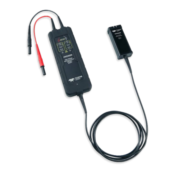
- Page 1 Operator's Manual HVD3000 Series High-Voltage Differential Probes...
- Page 3 HVD3000 Series High-Voltage Differential Probes Operator's Manual July, 2015...
- Page 4 Teledyne LeCroy documentation for their own internal educational purposes. Teledyne LeCroy is a trademark of Teledyne LeCroy, Inc. Other product or brand names are trademarks or requested trademarks of their respective holders. Information in this publication supersedes all earlier versions. Specifications are subject to change without notice.
-
Page 5: Table Of Contents
Contents Introduction Safety Voltage Derating for HVD3000 Accessories HVD310x Probes HVD310x Probe Kit HVD310x Specifications HVD3206 Probe HVD3206 Probe Kit HVD3206 Specifications HVD3605 Probe HVD3605 Probe Kit HVD3605 Specifications Functional Test Procedure Performance Verification Procedure Required Equipment Preliminary Procedure Certification Procedure Checking Probe Attenuation in XStream Browser HVD3000 Test Record Operation... - Page 6 HVD3000 Series High-Voltage Differential Probes Operator's Manual Certifications EMC Compliance Safety Compliance Environmental Compliance Warranty...
-
Page 7: Introduction
(V/div) setting, and the offset adjust is unified with that of the oscilloscope (maximum offset depends on the V/div setting and the oscilloscope model). In general, Teledyne LeCroy 12-bit High Resolution Oscilloscopes (HRO) and HD4096 High Definition Oscilloscopes (HDO) provide the most offset capability over the widest range of V/div settings. -
Page 8: Safety
HVD3000 Series High-Voltage Differential Probes Operator's Manual Safety To maintain the probe in a correct and safe condition, observe generally accepted safety procedures in addition to the precautions specified in this section. The overall safety of any system incorporating this product is the responsibility of the assembler of the system. -
Page 9: Operating Environment
Do not bend cables excessively. The input leads have a jacket wear indicator that shows through when the jacket is excessively worn. If the white "WEAR" indicator on the input leads is visible, cease use and contact Teledyne LeCroy service for repair or replacement. -
Page 10: Voltage Derating For Hvd3000 Accessories
HVD3000 Series High-Voltage Differential Probes Operator's Manual Voltage Derating for HVD3000 Accessories Derated Max. Input Voltage for Combined Probe and Accessory Part Number Accessory (from either input to ground) * Spade Terminals PK-HVA-05 1000 V CAT III Safety Alligator Clips... -
Page 11: Hvd310X Probes
HVD310x Probes HVD310x Probes HVD310x Probe Kit HVD310x Probe Kit The HVD310x probes are delivered with the following: ‡ Item Description Safety Rating* Part Number Spade Designed to connect to terminal Insulated PK-HVA-05 Terminals strips, posts and screws, the overall 1000 V CAT III length is 63 mm (2.48 inches). - Page 12 HVD3000 Series High-Voltage Differential Probes Operator's Manual ‡ Item Description Safety Rating* Part Number The clip is designed to securely Insulated PK-HVA-04 Plunger grasp thick wires, cables, ground 1000 V CAT III Alligator Clips leads, rails, and screw heads. The overall length is 153 mm (6.02...
-
Page 13: Hvd310X Specifications
HVD310x Probes HVD310x Specifications For the current specifications, see the product datasheet at teledynelecroy.com. Below are some key product specifications. Specifications are subject to change without notice. Guaranteed Specifications HVD3102 HVD3106 HVD3106-6M Bandwidth (probe only) 25 MHz 120 MHz 80 MHz Risetime 10-90 % 14 ns 2.9 ns... - Page 14 HVD3000 Series High-Voltage Differential Probes Operator's Manual Bandwidth HVD3102 T YPICAL ANDWIDTH HVD3106 T YPICAL ANDWIDTH...
- Page 15 HVD310x Probes HVD3106-6M T YPICAL ANDWIDTH...
- Page 16 HVD3000 Series High-Voltage Differential Probes Operator's Manual Common Mode Rejection Ratio HVD3102 T CMRR P YPICAL ERFORMANCE HVD3106 T CMRR P YPICAL ERFORMANCE...
- Page 17 HVD310x Probes Voltage Derating and Burn Limit The Maximum Input Voltage curve (solid line) shows the maximum voltage that can be applied to the HVD310x probe inputs without risking damage to the probe. The lower Burn Limit curve (dashed line) shows the maximum voltage that can be applied to the probe inputs while the operator is handling the inputs.
-
Page 18: Hvd3206 Probe
HVD3000 Series High-Voltage Differential Probes Operator's Manual HVD3206 Probe HVD3206 Probe Kit HVD3206 Probe Kit The HVD3206 probe is delivered with the following: ‡ Item Description Safety Rating* Part Number 6kV Alligator Designed to reliably grip large 6000 V CAT I **... -
Page 19: Hvd3206 Specifications
HVD3206 Probe HVD3206 Specifications For the current specifications, see the product datasheet at teledynelecroy.com. Below are some key product specifications. Specifications are subject to change without notice. Guaranteed Specifications HVD3206 Bandwidth (probe only) 120 MHz Risetime 10-90 % 2.9 ns CMRR Test Limits, 23 C 80 dB @ 50 Hz 60 dB @ 1 MHz... - Page 20 HVD3000 Series High-Voltage Differential Probes Operator's Manual Bandwidth HVD3206 T YPICAL ANDWIDTH Common Mode Rejection Ratio HVD3206 T CMRR P YPICAL ERFORMANCE...
- Page 21 HVD3206 Probe Voltage Derating and Burn Limit The Maximum Input Voltage curve (solid line) shows the maximum voltage that can be applied to the HVD3206 probe inputs without risking damage to the probe. The lower Burn Limit curve (dashed line) shows the maximum voltage that can be applied to the probe inputs while the operator is handling the inputs.
-
Page 22: Hvd3605 Probe
HVD3000 Series High-Voltage Differential Probes Operator's Manual HVD3605 Probe HVD3605 Probe Kit HVD3605 Probe Kit The HVD3605 probe is delivered with the following: ‡ Item Description Safety Rating* Part Number 6kV Alligator Designed to reliably grip large 6000 V CAT I **... -
Page 23: Hvd3605 Specifications
HVD3605 Probe HVD3605 Specifications For the current specifications, see the product datasheet at teledynelecroy.com. Below are some key product specifications. Specifications are subject to change without notice. Guaranteed Specifications HVD3605 Bandwidth (probe only) 100 MHz Risetime 10-90 % 4.3 ns CMRR Test Limits, 23 C 80 dB @ 50 Hz 60 dB @ 10 kHz... - Page 24 HVD3000 Series High-Voltage Differential Probes Operator's Manual Bandwidth HVD3605 T YPICAL ANDWIDTH Common Mode Rejection Ratio HVD3605 T CMRR P YPICAL ERFORMANCE...
- Page 25 HVD3605 Probe Voltage Derating and Burn Limit The Maximum Input Voltage curve (solid line) shows the maximum voltage that can be applied to the HVD3605 probe inputs without risking damage to the probe. The lower Burn Limit curve (dashed line) shows the maximum voltage that can be applied to the probe inputs while the operator is handling the inputs.
-
Page 26: Functional Test Procedure
HVD3000 Series High-Voltage Differential Probes Operator's Manual Functional Test Procedure This procedure should be performed to confirm the basic operation of an HVD3000 series probe, or to aid in determining the source of a problem rather than to verify the accuracy of the probe. -
Page 27: Performance Verification Procedure
This procedure can be used to verify the warranted characteristics of an HVD3000 series probe. If the product does not meet specifications, it should be returned to a Teledyne LeCroy service center. As there are no user accessible adjustments, there is no adjustment procedure. -
Page 28: Preliminary Procedure
HVD3000 Series High-Voltage Differential Probes Operator's Manual Preliminary Procedure 1. Connect the probe under test to the female end of the ProBus Extension Cable. Connect the male end of the ProBus Extension Cable to channel 1 (C1) of the oscilloscope. -
Page 29: Checking Probe Attenuation In Xstream Browser
This completes the Performance Verification Procedure. Complete and file the Test Record as required to support your internal calibration procedure. If the criteria in steps 14 or 19 are not met, contact your local Teledyne LeCroy service center. Checking Probe Attenuation in XStream Browser Probe attenuation and other values can be found by using the XStream Browser application that is installed with the oscilloscope firmware. -
Page 30: Hvd3000 Test Record
HVD3000 Series High-Voltage Differential Probes Operator's Manual HVD3000 Test Record Serial Number: Asset / Tracking Number: Date: Technician: Calibration Equipment Model Serial Number Due Date Oscilloscope Digital Multimeter Function Generator 1 1 In this Performance Verification Procedure, the function generator is used for making relative measurements. The output of the generator is measured with a DMM or oscilloscope. -
Page 31: Operation
Operation Operation Connecting to the Test Instrument The HVD3000 Series probes have been designed for use with Teledyne LeCroy oscilloscopes equipped with the ProBus interface. When you attach the probe output connector to the oscilloscope’s input connector, the instrument will: Recognize the probe Set the oscilloscope input termination to 1 MΩ... -
Page 32: Operating With An Oscilloscope
Operating with an Oscilloscope When the probe is connected to a Teledyne LeCroy oscilloscope, the displayed scale factor and measurement values will be adjusted to account for the effective gain of the probe. The probe’s internal attenuation is shown on the Probe dialog, which is added to the oscilloscope's... - Page 33 Operation connected. This may be calculated as follows: Oscilloscope Front End V/Div = (Probe and Oscilloscope) V/Div ÷ Probe_Attenuation Once the oscilloscope front end V/div value is known, then it is possible to know the maximum offset available in the oscilloscope at this V/div setting either by referencing the oscilloscope specifications or setting the maximum offset value on the oscilloscope for that V/div setting.
- Page 34 HVD3000 Series High-Voltage Differential Probes Operator's Manual x100 x200 x500 x1000 x2000 (<7V/div) (<7V/div) (<28V/div) (>7V/div) (>7V/div) (>28V/div) 3102 200Vpk 2000Vpk 3106 200Vpk 2000Vpk 3206 200Vpk 2000Vpk 3605 760Vpk 7600Vpk NOTE: Since this AC coupling is on the probe output, DC voltages beyond the linear range of the probe will cause the amplifier to saturate and make the displayed waveform inaccurate.
-
Page 35: Maintenance
Performance Verification Procedure is included in this manual. Service Strategy The HVD3000 series probes utilize fine-pitch surface mount devices. It is, therefore, impractical to attempt repair in the field. Defective probes must be returned to a Teledyne LeCroy service facility for diagnosis and exchange. -
Page 36: Returning A Product For Service
4. Pack the product case in a cardboard shipping box with adequate padding to avoid damage in transit. 5. Mark the outside of the box with the shipping address given to you by Teledyne LeCroy; be sure to add the following: ATTN: <RMA code assigned by Teledyne LeCroy>... -
Page 37: Contact Us
Rm. 2002 Support: Ph: 86-10-82800245 Ph: 800-553-2769 Service.China@teledynelecroy.com support@teledynelecroy.com Korea US Protocol Solutions Group Teledyne LeCroy Korea Teledyne LeCroy 10th fl. 333 Yeongdong-daero 3385 Scott Boulevard Gangnam-gu Santa Clara, CA, 95054, USA Seoul 135-280, Korea teledynelecroy.com teledynelecroy.com/korea Sales and Service:... -
Page 38: Reference
HVD3000 Series High-Voltage Differential Probes Operator's Manual Reference Common Mode Rejection Ratio The ideal differential probe/amplifier would sense and amplify only the differential mode voltage component and reject the entire common mode voltage component. Real differential amplifiers are not perfect, and a small portion of the common mode voltage component appears at the output. -
Page 39: Differential Mode Range And Common Mode Range
Reference Differential Mode Range and Common Mode Range Differential Mode range is the maximum signal that can be applied between the + and - inputs without overloading the amplifier, which otherwise would result in clipping or distorting of the waveform measured by the oscilloscope. The Common Mode Range is the maximum voltage with respect to earth ground that can be applied to either input. -
Page 40: Certifications
HVD3000 Series High-Voltage Differential Probes Operator's Manual Certifications EMC Compliance EC Declaration of Conformity - EMC The probe meets the intent of EC Directive 2004/108/EC for Electromagnetic Compatibility. Compliance was demonstrated to the following specifications as listed in the Official Journal of... -
Page 41: Safety Compliance
Many countries prohibit the disposal of waste electronic equipment in standard waste receptacles. For more information about proper disposal and recycling of your Teledyne LeCroy product, please visit teledynelecroy.com/recycle. Restriction of Hazardous Substances (RoHS) The product and its accessories conform to the 2011/65/EU RoHS2 Directive. -
Page 42: Warranty
Teledyne LeCroy shall not be responsible for any defect, damage, or failure caused by any of the following: a) attempted repairs or installations by personnel other than Teledyne LeCroy representatives, b) improper connection to incompatible equipment, or c) use of non-Teledyne LeCroy supplies. - Page 44 925782-00 July, 2015...