Table of Contents
Advertisement
Quick Links
GENERA TOR - DIESEL
GENERA
GENERA
ASSEMBLY AND OPERATING INSTRUCTIONS
3491 Mission Oaks Blvd., Camarillo, CA 93011
Visit our Web site at http://www.harborfreight.com
Copyright © 2002 by Harbor Freight T ools
this manual or any artwork contained herein may be reproduced in any shape
or form without the express written consent of Harbor Freight T ools.
For technical questions and replacement parts, please call 1-800-444-3353
CHICAGO
Electric
Generators
20 KV
20 KV A
20 KV
20 KV
20 KV
Model
02514
®
. All rights reserved. No portion of
Advertisement
Table of Contents

Related Manuals for Chicago Electric 02514


Summary of Contents for Chicago Electric 02514
- Page 1 20 KV 20 KV A 20 KV 20 KV 20 KV Model 02514 ASSEMBLY AND OPERATING INSTRUCTIONS 3491 Mission Oaks Blvd., Camarillo, CA 93011 Visit our Web site at http://www.harborfreight.com Copyright © 2002 by Harbor Freight T ools ® . All rights reserved. No portion of this manual or any artwork contained herein may be reproduced in any shape or form without the express written consent of Harbor Freight T ools.
-
Page 2: Specifications
Keep your invoice with this manual. Write the invoice number on the inside of the front cover. Keep the manual and invoice in a safe and dry place for future reference. SKU 02514 Page 2... -
Page 3: Safety Warnings And Precautions
The supporting floor should be level, and strong enough to safely hold the weight of the generator. If the floor is not level, strong cross members should be placed under the full length of the generator steel frame at its low side. SKU 02514 Page 3... - Page 4 If this occurs, open exhaust system drain plugs, if equipped, and allow the gases to dissipate before attempting to restart the generator. Use only engine manufacturer’s recommended fuel, oil, and cooling fluids (see engine manufacturer’s instruction manuals). SKU 02514 Page 4...
- Page 5 The generator must be earth-grounded in accordance with all relevant electrical codes and standards before operation. Before performing any maintenance or connecting or disconnecting any electrical load connections, the negative (–) battery cable must be removed from the battery. SKU 02514 Page 5...
- Page 6 If there is any doubt, do not operate the generator. Maintenance . For your safety, service and maintenance should be performed regularly by a qualified technician. Never work alone on the generator. SKU 02514 Page 6...
-
Page 7: Installation
Caution: Do not attempt to start or crank the generator engine before it has been checked for sufficient and recommended oil, coolant, and the battery is fully charged. Otherwise, engine damage may occur. SKU 02514 Page 7... - Page 8 If one phase draws more current than the others, damage can occur to the generator. Install the 1-1/2” rigid conduit from the generator connection box to the outside of the generator housing. Mount a junction box which connects it to the external rigid conduit routed to the transfer switch. SKU 02514 Page 8...
- Page 9 “Do Not T ouch - Wiring in Progress”. Connect the utility power supply leads to the transfer switch. Connect the circuit load leads from the emergency distribution panel (if used) to the transfer switch. Generator Connection Box 115V 220V Typical Emergency Power System SKU 02514 Page 9...
-
Page 10: Operation
Verify that the ON/OFF switch is in the Off position. Check fuel level. If low, refill with clean diesel fuel. Check oil level. Add oil if low. Check coolant level. Add coolant if low. Check voltage cables junction box for secure and clean connections. SKU 02514 Page 10... - Page 11 Turn off the utility power supply to the transfer switch from the utility main line circuit breaker. Set the transfer switch to the standby (generator-to-load) position. Controls and Indicators The table on the next page defines each item on the Control Panel. SKU 02514 Page 11...
-
Page 12: Controls And Indicators
View the ampere and voltage meters on the control panel. Adjust voltage regulator to change voltage, if necessary. T otal ampere should not exceed the maximum capacity of the generator. Listen for unusual noises, vibration, or other indications of abnormal operation. Check for oil leaks and evidence of overheating. SKU 02514 Page 12... -
Page 13: Maintenance
SHOULD BE UNDERTAKEN BY CERTIFIED AND LICENSED TECHNICIANS AND NOT BY THE BUYER. THE BUYER ASSUMES ALL RISK AND LIABILITY ARISING OUT OF HIS OR HER REPAIRS TO THE ORIGINAL PRODUCT OR REPLACEMENT PARTS THERETO, OR ARISING OUT OF HIS OR HER INSTALLATION OF REPLACEMENT PARTS THERETO. SKU 02514 Page 13... - Page 14 OIL PRESSURE TRANSDUCER RESET STOP Fig.3 Diagram For Protection Patter Plate Of Diesel Generating Set Oil Pressure And Water Temperature Plug 1 (Female) Plug 2 (Male) Fig.4Instruction For The Plug Of Diesel Generating Set Protection Pattern Plate SKU 02514 Page 14...
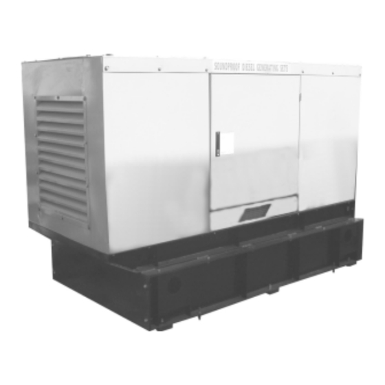
- Page 15 2.Harmonic Coil Of The Auxiliary 3.Automatic Voltage Regulator 4.AVR Winding 5.Silicon Rectifier 6.Stator's Harmonic Generator Layout Diagram 1.DIesel Engine 2.Couple Kit 3.Generator 4.Sound-Proof Housing 5.Fuel Tank 6.Contorl Cables 7.Contorl Panel 8.Base Frame 9.Anti-Vibration Mounting Base 10.Exhaust Pipe 11.Radiator SKU 02514 Page 15...
- Page 16 £ £ £ 1.Change Switch 2.Indicating Lamp 3.Calculagraph 4.Meter 5.Start Key 6.DC Charge Current Meter 7.Generator 8.Start Motor 9.Preheat Winding 10.Battery Wiring Diagram Of Engine Control SKU 02514 Page 16...