Table of Contents
Advertisement
Quick Links
Advertisement
Table of Contents

Related Manuals for York YK Style H


Summary of Contents for York YK Style H
- Page 1 OPTIVIEW™ CONTROL CENTER CENTRIFUGAL LIQUID CHILLERS OPERATION MANUAL New Release Form 160.76-O2 (615) MODEL YK (STYLE H) R-134a WITH OPTIVIEW™ CONTROL CENTER FOR ELECTRO-MECHANICAL STARTER, SOLID STATE STARTER AND VARIABLE SPEED DRIVE LD15222 Issue Date: June 15, 2015...
- Page 2 FORM 160.76-O2 issue date: 6/15/2015 IMPORTANT! READ BEFORE PROCEEDING! GENERAL SAFETY GUIDELINES This equipment is a relatively complicated apparatus. which it is situated, as well as severe personal injury or During rigging, installation, operation, maintenance, death to themselves and people at the site. or service, individuals may be exposed to certain com- This document is intended for use by owner-authorized ponents or conditions including, but not limited to:...
- Page 3 FORM 160.76-O2 issue date: 6/15/2015 CHANGEABILITY OF THIS DOCUMENT In complying with Johnson Controls’ policy for con- regarding the applicability of these documents, rig- tinuous product improvement, the information con- ging, lifting, and operating/service personnel should tained in this document is subject to change without verify whether the equipment has been modified and notice.
- Page 4 FORM 160.76-O2 issue date: 6/15/2015 NOMENCLATURE – STYLE (Design Level) MOTOR CODE POWER SUPPLY – for 60 Hz 5 for 50 Hz COMPRESSOR CODE* CONDENSER CODE* EVAPORATOR CODE* * Refer to YK Engineering Guide for (Form 160.76-EG1) Shell/Motor/Compressor combinations. MODEL* JOHNsON CONtROLs...
-
Page 5: Table Of Contents
FORM 160.76-O2 issue date: 6/15/2015 TABLE OF CONTENTS SECTION 1 - DESCRIPTION OF SYSTEM AND FUNDAMENTALS OF OPERATION .......... 9 SYSTEM OPERATION DESCRIPTION ......................9 Capacity Control ............................. 10 SECTION 2 - OPTIVIEW CONTROL CENTER INTRODUCTION ................13 Optiview Control Center ..........................15 Safety Stop .............................. - Page 6 FORM 160.76-O2 issue date: 6/15/2015 TABLE OF CONTENTS (CONT'D) Schedule Screen ............................131 User Screen ..............................133 COMMS Screen ............................135 Printer Screen .............................. 137 Sales Order Screen ............................139 Operations Screen ............................141 History Screen .............................. 143 History Details Screen ..........................145 Security Log Screen .............................
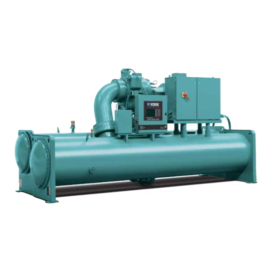
- Page 7 FORM 160.76-O2 issue date: 6/15/2015 LIST OF FIGURES FIGURE 1 - Model YK Chiller ............................9 FIGURE 2 - Compressor Pre-rotation Vanes ......................10 FIGURE 3 - Refrigerant Flow-Thru Chiller....................... 11 FIGURE 4 - Optiview Control Center........................15 FIGURE 5 - Home Screen ............................21 FIGURE 6 - Home Screen With Stop Button ......................23 FIGURE 7 - System Screen ............................25 FIGURE 8 - Evaporator Screen ..........................27...
- Page 8 FORM 160.76-O2 issue date: 6/15/2015 LIST OF FIGURES (CONT'D) FIGURE 55 - Custom View Setup Screen ......................153 FIGURE 56 - Trend Screen ...........................155 FIGURE 57 - Trend Setup Screen .........................157 FIGURE 58 - Advanced Trend Setup Screen ......................159 FIGURE 59 - Common Slots Screen ........................161 FIGURE 60 - Printer ..............................189 FIGURE 62 - Communications Block Diagram......................193 FIGURE 61 - Breckman Printer ..........................193...
-
Page 9: Section 1 - Description Of System And Fundamentals Of Operation
Drive (optional). flow control. When the compressor motor is driven by a YORK The chiller is controlled by a modern state of the art Solid State Starter, one of two different starters could Microcomputer Control Center that monitors its opera- be applied. -
Page 10: Capacity Control
Pre-rotation Vanes (PRV), located at the entrance to the compressor impeller, compensate for When the compressor motor is driven by a YORK variation in load (Refer to Figure 2 on Page 10). Variable Speed Drive, there could be a Variable Speed... -
Page 11: Figure 3 - Refrigerant Flow-Thru Chiller
FORM 160.76-O2 SECTION 1 - DESCRIPTION OF SYSTEM AND FUNDAMENTALSOF OPERATION issue date: 6/15/2015 Refrigerant Flow-Thru Chiller (Falling Film Evaporator) YK Mod G Refrigerant Flow-Thru Cross-Section Diagram (Falling-Film Evaporator) LEGEND High Pressure Vapor High Pressure Liquid Refrigerant Low Pressure Liquid Refrigerant Low Pressure Vapor COMPRESSOR PRE-ROTATION... - Page 12 FORM 160.76-O2 SECTION 1 - DESCRIPTION OF SYSTEM AND FUNDAMENTALSOF OPERATION issue date: 6/15/2015 THIS PAGE INTENTIONALLY LEFT BLANK JOHNsON CONtROLs...
-
Page 13: Section 2 - Optiview Control Center Introduction
Instructions for specific operations are provided on networking protocol through the Building Automation many of the screens. System (BAS), YORK Chillers not only work well in- The graphic display also allows information to be rep- dividually, but also as a team. This BAS communica- resented in both English (temperatures in °F and pres-... - Page 14 FORM 160.76-O2 SECTION 2 - OPTIVIEW CONTROL CENTER INTRODUCTION issue date: 6/15/2015 The chiller operating program resides in the OptiV- Software versions (Y.OPT.01.xx.yzz are alpha-numeric iew Control Center Microboard. The Control Center is codes that represent the application language package equipped with the following Microboard: and revision levels per be-low.
-
Page 15: Optiview Control Center
FORM 160.76-O2 SECTION 2 - OPTIVIEW CONTROL CENTER INTRODUCTION issue date: 6/15/2015 OPTIVIEW CONTROL CENTER ± LD19567 FIGURE 4 - OPTIVIEW CONTROL CENTER The OptiView™ Control Center display is highlighted Cursor Arrow keys are pro- by a full screen graphics display. This display is nested vided to allow movement on within a standard keypad, and is surrounded by SOFT screens which contain a large... -
Page 16: Safety Stop
FORM 160.76-O2 SECTION 2 - OPTIVIEW CONTROL CENTER INTRODUCTION issue date: 6/15/2015 • Remotely through digital inputs in digital or ana- with the ‘>’ symbol; if it is below the normal operating log remote mode range, the low limit value will be displayed along with the ‘<’... -
Page 17: Navigation
FORM 160.76-O2 SECTION 2 - OPTIVIEW CONTROL CENTER INTRODUCTION issue date: 6/15/2015 Setpoints Manual Controls The Control Center uses the setpoint values to control Some keys are used to perform manual control func- the chiller and other devices connected to the chiller tions. - Page 18 FORM 160.76-O2 SECTION 2 - OPTIVIEW CONTROL CENTER INTRODUCTION issue date: 6/15/2015 Home Screen (Page 21) System Screen (Page 25) Evaporator (Page 27) History (Page 143) Heat Pump (Page 41) History Details (Page 145) Condenser (Page 31) Security Log Screen (Page 147) Level Control (Page 45) Security Log Details Screen (Page 149) Heat Recovery (Page 35)
-
Page 19: Table 1 - Addresses And Associated Data
FORM 160.76-O2 SECTION 2 - OPTIVIEW CONTROL CENTER INTRODUCTION issue date: 6/15/2015 ANALOG INPUT RANGES The following table indicates the valid display range the < or > symbols will be displayed beside the mini- for each of the analog input values. In the event that the mum or maximum value, respectively. - Page 20 FORM 160.76-O2 SECTION 2 - OPTIVIEW CONTROL CENTER INTRODUCTION issue date: 6/15/2015 THIS PAGE INTENTIONALLY LEFT BLANK JOHNsON CONtROLs...
-
Page 21: Home Screen
FORM 160.76-O2 SECTION 2 - OPTIVIEW CONTROL CENTER INTRODUCTION issue date: 6/15/2015 HOME SCREEN LD19445 FIGURE 5 - HOME SCREEN OVERVIEW Motor Run (LED) Is ON when the digital output controlling the motor When the chiller system is powered on, the above de- starter contact is on. - Page 22 FORM 160.76-O2 SECTION 2 - OPTIVIEW CONTROL CENTER INTRODUCTION issue date: 6/15/2015 Heating Condenser Liquid Temperature – Print Return Access Level Required: VIEW Use this key to generate a hard-copy report of the Displays the temperature of the liquid as it enters the heating condenser tube bundle.
-
Page 23: Figure 6 - Home Screen With Stop Button
FORM 160.76-O2 SECTION 2 - OPTIVIEW CONTROL CENTER INTRODUCTION issue date: 6/15/2015 LD19446 FIGURE 6 - HOME SCREEN WITH STOP BUTTON Motor NAVIGATION A detailed view of the motor controller parameters, System specific to the controller type presently utilized on the Used to provide additional system information. - Page 24 FORM 160.76-O2 SECTION 2 - OPTIVIEW CONTROL CENTER INTRODUCTION issue date: 6/15/2015 THIS PAGE INTENTIONALLY LEFT BLANK JOHNsON CONtROLs...
-
Page 25: System Screen
FORM 160.76-O2 SECTION 2 - OPTIVIEW CONTROL CENTER INTRODUCTION issue date: 6/15/2015 SYSTEM SCREEN LD19447 FIGURE 7 - SYSTEM SCREEN OVERVIEW CONDENSER LIQUID TEMPERATURE – EN- TERING This screen gives a general overview of common chill- er parameters for both shells. Displays the temperature of the liquid as it enters the condenser. -
Page 26: Displays The Temperature Of The Liquid As It Enters The Condenser
FORM 160.76-O2 SECTION 2 - OPTIVIEW CONTROL CENTER INTRODUCTION issue date: 6/15/2015 Head Pressure Heating Condenser Liquid Temperature – Leaving Displays the pressure difference between the condens- er and evaporator (condenser minus evaporator). This Displays the temperature of the liquid as it leaves the is also called the Head Pressure. -
Page 27: Evaporator Screen
FORM 160.76-O2 SECTION 2 - OPTIVIEW CONTROL CENTER INTRODUCTION issue date: 6/15/2015 EVAPORATOR SCREEN LD19448 FIGURE 8 - EVAPORATOR SCREEN OVERVIEW Evaporator Small Temperature Difference Displays the difference between the Leaving Chilled This screen displays a cutaway view of the chiller Liquid temperature and the Evaporator Refrigerant evaporator. - Page 28 FORM 160.76-O2 SECTION 2 - OPTIVIEW CONTROL CENTER INTRODUCTION issue date: 6/15/2015 Leaving Chilled Liquid Temperature Setpoints Local Leaving Chilled Liquid Temperature – – Shutdown Setpoint Displays the Leaving Chilled Liquid Temperature at Access Level Required: OPERATOR which the chiller will shutdown on Leaving Chilled This value allows the user to define the Leaving Liquid –...
- Page 29 FORM 160.76-O2 SECTION 2 - OPTIVIEW CONTROL CENTER INTRODUCTION issue date: 6/15/2015 Leaving Chilled Liquid Temperature from going below Sensitivity the minimum allowed value: 36°F (water), 34°F (water Access Level Required: SERVICE with smart freeze enabled) or 6°F (brine). For example, This value allows the user to adjust the sensitivity of if the Leaving Chilled Liquid Temperature Setpoint is the Leaving Chilled Liquid Temperature control.
- Page 30 FORM 160.76-O2 SECTION 2 - OPTIVIEW CONTROL CENTER INTRODUCTION issue date: 6/15/2015 THIS PAGE INTENTIONALLY LEFT BLANK JOHNsON CONtROLs...
-
Page 31: Condenser Screen
FORM 160.76-O2 SECTION 2 - OPTIVIEW CONTROL CENTER INTRODUCTION issue date: 6/15/2015 CONDENSER SCREEN LD19449 FIGURE 9 - CONDENSER SCREEN OVERVIEW Leaving Condenser Liquid Temperature Setpoint This screen displays a cutaway view of the chiller con- Displays the active setpoint to which the Heat Pump denser. - Page 32 FORM 160.76-O2 SECTION 2 - OPTIVIEW CONTROL CENTER INTRODUCTION issue date: 6/15/2015 Condenser Pressure Condenser Refrigerant Level Displays the refrigerant pressure in the condenser. Displays the present position of the refrigerant level if this function is enabled. Leaving Heating Condenser Liquid Tempera- ture Active Level Setpoint Displays the temperature of the liquid as it leaves the...
- Page 33 FORM 160.76-O2 SECTION 2 - OPTIVIEW CONTROL CENTER INTRODUCTION issue date: 6/15/2015 Heat Recovery Heat Pump Access Level Required: SERVICE Access Level Required: VIEW Moves to a sub screen allowing programming and Moves to a sub screen allowing programming and viewing of the Heat Recovery setpoints and parame- viewing of the Heat Pump Setpoints and parameters.
- Page 34 FORM 160.76-O2 SECTION 2 - OPTIVIEW CONTROL CENTER INTRODUCTION issue date: 6/15/2015 THIS PAGE INTENTIONALLY LEFT BLANK JOHNsON CONtROLs...
-
Page 35: Heat Recovery/Head Pressure Control Screen
FORM 160.76-O2 SECTION 2 - OPTIVIEW CONTROL CENTER INTRODUCTION issue date: 6/15/2015 HEAT RECOVERY/HEAD PRESSURE CONTROL SCREEN LD19450 FIGURE 10 - HEAT RECOVERY/HEAD PRESSURE CONTROL SCREEN OVERVIEW ery is disabled, the condenser flow animation is based on the standard Condenser Flow Switch. This screen This screen displays all parameters related to the Heat also serves as a gateway to controlling the Refrigerant Recovery feature. - Page 36 FORM 160.76-O2 SECTION 2 - OPTIVIEW CONTROL CENTER INTRODUCTION issue date: 6/15/2015 Leaving Heating Condenser Liquid ing conditions cause it to switch over to Head Pressure Temperature Control. When performing Hot Water Control, Hot Water is displayed. When performing Head Pressure Displays the temperature of the liquid as it leaves the Control, Head Pressure is displayed.
- Page 37 FORM 160.76-O2 SECTION 2 - OPTIVIEW CONTROL CENTER INTRODUCTION issue date: 6/15/2015 Head Pressure Setpoint Control Valve Output Settings – Auto (15.0 to 60 PSID; default 23.0 PSID) Sets the pressure Places the Control Valve in automatic control. Only ap- differential to which the Control Valve will control pears when Hot Water Control is enabled or Head Pres- the Head Pressure.
- Page 38 FORM 160.76-O2 SECTION 2 - OPTIVIEW CONTROL CENTER INTRODUCTION issue date: 6/15/2015 NAVIGATION Home Returns user to HOME Screen. Condenser Returns user to CONDENSER Screen. JOHNsON CONtROLs...
-
Page 39: Head Pressure Control Screen
FORM 160.76-O2 SECTION 2 - OPTIVIEW CONTROL CENTER INTRODUCTION issue date: 6/15/2015 HEAD PRESSURE CONTROL SCREEN LD19450 FIGURE 11 - HEAD PRESSURE CONTROL SCREEN OVERVIEW DISPLAY ONLY This screen displays all parameters related to the Head Entering Condenser Liquid Temperature Pressure Control feature. - Page 40 FORM 160.76-O2 SECTION 2 - OPTIVIEW CONTROL CENTER INTRODUCTION issue date: 6/15/2015 be at minimum; the 100% output will be at maximum. Change Setpoints If set to reverse, the 0.0% output will be at maximum; Use to enter the Head Pressure Control PID variables the 100% output will be at minimum.
-
Page 41: Heat Pump Screen
FORM 160.76-O2 SECTION 2 - OPTIVIEW CONTROL CENTER INTRODUCTION issue date: 6/15/2015 HEAT PUMP SCREEN LD19566 FIGURE 12 - HEAT PUMP SCREEN All setpoints pertinent to this feature are maintained on OVERVIEW this screen. Heat Pump is an available option on certain models of YK chillers. - Page 42 FORM 160.76-O2 SECTION 2 - OPTIVIEW CONTROL CENTER INTRODUCTION issue date: 6/15/2015 ture Setpoint in Heating mode. See the Leaving Con- mode. It determines the magnitude of PRV movement denser Liquid Temperature Setpoint – Range Setpoint in response to a change in Leaving Condenser Liquid description below.
- Page 43 FORM 160.76-O2 SECTION 2 - OPTIVIEW CONTROL CENTER INTRODUCTION issue date: 6/15/2015 setpoint is 90°F, the remote device can set the Leaving start when this temperature is reached. This setpoint Condenser Liquid Temperature Setpoint over the range can be used to reduce chiller cycling by delaying the of 90 to 80°F.
- Page 44 FORM 160.76-O2 SECTION 2 - OPTIVIEW CONTROL CENTER INTRODUCTION issue date: 6/15/2015 THIS PAGE INTENTIONALLY LEFT BLANK JOHNsON CONtROLs...
-
Page 45: Refrigerant Level Control Screen
FORM 160.76-O2 SECTION 2 - OPTIVIEW CONTROL CENTER INTRODUCTION issue date: 6/15/2015 REFRIGERANT LEVEL CONTROL SCREEN LD19451 FIGURE 13 - REFRIGERANT LEVEL CONTROL SCREEN actual level is 32% to 47%, the level is shown as 70% OVERVIEW full. When the actual level is 48% to 63%, the level This screen displays a cutaway view of the chiller con- is shown as 80% full. - Page 46 FORM 160.76-O2 SECTION 2 - OPTIVIEW CONTROL CENTER INTRODUCTION issue date: 6/15/2015 Level Control Valve Command Close Indicates the valve command as a percentage of full Pressing this button will set the Condenser Level Con- open. It is only displayed when the valve control meth- trol Valve Mode to Manual if it had been in Auto and od is analog.
-
Page 47: Compressor Screen
FORM 160.76-O2 SECTION 2 - OPTIVIEW CONTROL CENTER INTRODUCTION issue date: 6/15/2015 COMPRESSOR SCREEN LD19452 FIGURE 14 - COMPRESSOR SCREEN (SCREEN SHOWN IS A UNIT WITH PROXIMITY PROBE) OVERVIEW displayed value includes offset pressure derived from auto-zeroing during the System Prelube. If either of the This screen displays a cutaway view of the chiller com- transducers used to calculate this differential is out of pressor, revealing the impeller, and shows all condi-... - Page 48 FORM 160.76-O2 SECTION 2 - OPTIVIEW CONTROL CENTER INTRODUCTION issue date: 6/15/2015 Oil Sump Temperature PRV Closing (LED) Displays the temperature of the oil in the sump Indicates whether the vanes are in the process of clos- ing. Discharge Temperature PRV Command Displays the temperature of the refrigerant in its gas- eous state at discharge of the compressor as it travels...
- Page 49 FORM 160.76-O2 SECTION 2 - OPTIVIEW CONTROL CENTER INTRODUCTION issue date: 6/15/2015 Surge Proximity Probe Calibrate Moves to the subscreen that allows viewing and pro- Only available if the chiller is stopped. Moves to the gramming of the Surge Protection feature. subscreen allowing calibration of the High Speed Thrust Bearing Proximity Probe sensor.
- Page 50 FORM 160.76-O2 SECTION 2 - OPTIVIEW CONTROL CENTER INTRODUCTION issue date: 6/15/2015 THIS PAGE INTENTIONALLY LEFT BLANK JOHNsON CONtROLs...
-
Page 51: Capacity Control Screen
FORM 160.76-O2 SECTION 2 - OPTIVIEW CONTROL CENTER INTRODUCTION issue date: 6/15/2015 CAPACITY CONTROL SCREEN LD19453 FIGURE 15 - CAPACITY CONTROL SCREEN OVERVIEW [Condenser Pressure] Override Threshold Displays the condenser pressure setpoint above which This screen applies to all VSD drive type chillers. the high condenser pressure capacity control override Some of the fields will not be visible depending upon takes effect. - Page 52 FORM 160.76-O2 SECTION 2 - OPTIVIEW CONTROL CENTER INTRODUCTION issue date: 6/15/2015 Motor Current % FLA • Condenser Pressure – Condenser Pressure Over- ride is in control. Displays the percentage of maximum motor current delivered to the motor, determined from the highest of • Evaporator Pressure- Evaporator Pressure Over- the three phase Motor Currents/Maximum Motor Cur- ride is in control.
- Page 53 FORM 160.76-O2 SECTION 2 - OPTIVIEW CONTROL CENTER INTRODUCTION issue date: 6/15/2015 the Local, Remote or BAS (ISN) LCLT programmed Manual Increment setpoint, depending on the control source selected. Access Level Required: SERVICE Only displayed when the unit is a Heating/Cooling This key enables the change increment to be set for unit.
- Page 54 FORM 160.76-O2 SECTION 2 - OPTIVIEW CONTROL CENTER INTRODUCTION issue date: 6/15/2015 ACC DETAILS Hot Gas Access Level Required: SERVICE Access Level Required: SERVICE Moves to the Hot Gas Bypass subscreen. This button Causes an instant navigation to the ACC Details will only be shown and enabled when the Access Level Screen.
-
Page 55: Capacity Control Setpoints Screen
FORM 160.76-O2 SECTION 2 - OPTIVIEW CONTROL CENTER INTRODUCTION issue date: 6/15/2015 CAPACITY CONTROL SETPOINTS SCREEN LD19453 FIGURE 16 - CAPACITY CONTROL SETPOINTS SCREEN (SCREEN SHOWN IS HEATING/COOLING UNIT WITH RAPTYR VSD) OVERVIEW Capacity Control Navigates to the Capacity Control Screen. This screen shows Service-level setpoints related to the Capacity Control logic. -
Page 56: Table 2 - Capacity Control Setpoint Programmable Settings
FORM 160.76-O2 SECTION 2 - OPTIVIEW CONTROL CENTER INTRODUCTION issue date: 6/15/2015 TABLE 2 - CAPACITY CONTROL SETPOINT PROGRAMMABLE SETTINGS ACCESS LEVEL/ PROGRAM SETTING LOW LIMIT HIGH LIMIT DEFAULT STATE LCHLT Setpoint Ramp Rate Service 0.1 ºF/s 2.0 ºF/s 0.1 ºF/s LCHLT Setpoint Start Offset Service 0.0 ºF (differential) -
Page 57: Anti-Surge Turning Screen
FORM 160.76-O2 SECTION 2 - OPTIVIEW CONTROL CENTER INTRODUCTION issue date: 6/15/2015 ANTI-SURGE TURNING SCREEN LD19466 FIGURE 17 - ANTI SURGE SCREEN (PRV CAPACITY CONTROL SCREEN SHOWN) OVERVIEW NAVIGATION This screen shows Service and Admin level setpoints Home related to the Anti-Surge Tuning logic. Navigates to the Home Screen. - Page 58 FORM 160.76-O2 SECTION 2 - OPTIVIEW CONTROL CENTER INTRODUCTION issue date: 6/15/2015 THIS PAGE INTENTIONALLY LEFT BLANK JOHNsON CONtROLs...
-
Page 59: Capacity Control Override Turning Screen
FORM 160.76-O2 SECTION 2 - OPTIVIEW CONTROL CENTER INTRODUCTION issue date: 6/15/2015 CAPACITY CONTROL OVERRIDE TURNING SCREEN LD19467 FIGURE 18 - CAPACITY CONTROL OVERRIDE TURNING SCREEN OVERVIEW Capacity Control Navigates to the Capacity Control Screen. This screen shows Service and Admin level setpoints related to the Anti-Surge Tuning logic. - Page 60 FORM 160.76-O2 SECTION 2 - OPTIVIEW CONTROL CENTER INTRODUCTION issue date: 6/15/2015 THIS PAGE INTENTIONALLY LEFT BLANK JOHNsON CONtROLs...
-
Page 61: Proximity Probe Calibration Screen
FORM 160.76-O2 SECTION 2 - OPTIVIEW CONTROL CENTER INTRODUCTION issue date: 6/15/2015 PROxIMITY PROBE CALIBRATION SCREEN 00305VIP FIGURE 19 - PROXIMITY PROBE CALIBRATION SCREEN OVERVIEW Oil Pressure Displays the pressure differential between the high This screen displays a cutaway view of the chiller com- side oil pressure transducer (compressor bearing input) pressor, revealing the Proximity Probe sensor and provides and the low side oil pressure transducer (oil sump). - Page 62 FORM 160.76-O2 SECTION 2 - OPTIVIEW CONTROL CENTER INTRODUCTION issue date: 6/15/2015 Start Calibration NAVIGATION Press this key to start the calibration. Home Access Level Required: VIEW Cancel Calibration Returns user to HOME Screen. Press this key to cancel calibration. Compressor Accept Calibration Access Level Required: VIEW...
-
Page 63: Hot Gas Bypass Screen
FORM 160.76-O2 SECTION 2 - OPTIVIEW CONTROL CENTER INTRODUCTION issue date: 6/15/2015 HOT GAS BYPASS SCREEN LD19454 FIGURE 20 - HOT GAS BYPASS SCREEN OVERVIEW PRV Position Displays the present Pre-rotation Vanes position as a This screen displays a cutaway view of the Hot Gas By- value between 0% (closed) and 100% (full open). - Page 64 FORM 160.76-O2 SECTION 2 - OPTIVIEW CONTROL CENTER INTRODUCTION issue date: 6/15/2015 ACC Surge Detected (LED) Setpoint. Only displayed if equipped with a VSD or MV VSD]. Maximum Open Illuminates momentarily when a surge is detected by (25 to 100%) the ACC function in the Microboard, while the drive is The maximum allowed position for the Hot Gas Valve running at less than maximum frequency.
-
Page 65: Surge Protection Screen
FORM 160.76-O2 SECTION 2 - OPTIVIEW CONTROL CENTER INTRODUCTION issue date: 6/15/2015 SURGE PROTECTION SCREEN LD13827 FIGURE 21 - SURGE PROTECTION SCREEN OVERVIEW DISPLAY ONLY This screen displays a cutaway view of the chiller com- Delta P/P pressor and all parameters relating to the Surge Pro- A parameter that represents the system differential or tection feature. - Page 66 FORM 160.76-O2 SECTION 2 - OPTIVIEW CONTROL CENTER INTRODUCTION issue date: 6/15/2015 Surge Avoidance Surge Detected (LED) If this setpoint is Disabled, refer to operation under Count Limit on Page 66. Illuminates momentarily when a surge is detected by the Surge Protection feature. If equipped with a VSD • If equipped with a compressor Variable Speed or MV VSD these are only the surges detected while Drive or MVVSD, the VSD output frequency...
- Page 67 FORM 160.76-O2 SECTION 2 - OPTIVIEW CONTROL CENTER INTRODUCTION issue date: 6/15/2015 Allows the user to define the maximum number of surge is invoked as described above. However, if the events (4 to 20; default 15; that can occur within a de- Surge Window Count exceeds the Count Limit fined period of time before an Excess Surge situation is at the completion of the 10 minute Extended Run...
- Page 68 FORM 160.76-O2 SECTION 2 - OPTIVIEW CONTROL CENTER INTRODUCTION issue date: 6/15/2015 THIS PAGE INTENTIONALLY LEFT BLANK JOHNsON CONtROLs...
-
Page 69: Variable Geometry Diffuser Screen
FORM 160.76-O2 SECTION 2 - OPTIVIEW CONTROL CENTER INTRODUCTION issue date: 6/15/2015 VARIABLE GEOMETRY DIFFUSER SCREEN LD19455 FIGURE 22 - VARIABLE GEOMETRY DIFFUSER SCREEN OVERVIEW VGD Closed Limit Switch Displays the status of the VGD Limit Switch. Dis- This screen displays information pertinent to the VGD played as CLOSED when the VGD is in the fully operation. - Page 70 FORM 160.76-O2 SECTION 2 - OPTIVIEW CONTROL CENTER INTRODUCTION issue date: 6/15/2015 It illuminates momentarily when a surge is detected by [VGD] Hold (Manual) the Surge Protection feature, regardless of the VSD op- This key puts the VGD in manual mode and sends a erating speed.
-
Page 71: Variable Geometry Diffuser Setpoints Screen
FORM 160.76-O2 SECTION 2 - OPTIVIEW CONTROL CENTER INTRODUCTION issue date: 6/15/2015 VARIABLE GEOMETRY DIFFUSER SETPOINTS SCREEN LD19456 FIGURE 23 - VARIABLE GEOMETRY DIFFUSER SETPOINTS SCREEN OVERVIEW The minimum difference between the High Limit Setpoint and the Low Limit Setpoint is 0.1VDC. If The Variable Geometry Diffuser setpoints are main- a Low Limit Setpoint is entered which is less than tained on this screen. - Page 72 FORM 160.76-O2 SECTION 2 - OPTIVIEW CONTROL CENTER INTRODUCTION issue date: 6/15/2015 VGD Position Open Pulse Setpoint. While this is in effect, PRV Posi- tion Override is displayed as Control Status. Shows the position of the VGD. 0 to 100% open. PRV Offset Maximum VGD Position (0 to 5%;...
-
Page 73: Variable Geometry Diffuser Calibration Screen
FORM 160.76-O2 SECTION 2 - OPTIVIEW CONTROL CENTER INTRODUCTION issue date: 6/15/2015 VARIABLE GEOMETRY DIFFUSER CALIBRATION SCREEN LD19457 FIGURE 24 - VARIABLE GEOMETRY DIFFUSER CALIBRATION SCREEN OVERVIEW 100% VGD Voltage Displays the feedback voltage calibration at the 100% This screen displays a cutaway view of the chiller com- position. - Page 74 FORM 160.76-O2 SECTION 2 - OPTIVIEW CONTROL CENTER INTRODUCTION issue date: 6/15/2015 Set 100% VGD NAVIGATION Pressed during the VGD calibration routine to indicate Home that the VGD is physically at the 100% position. Access Level Required: SERVICE Set 0% VGD Returns user to HOME Screen.
-
Page 75: Pre-Rotation Vanes Calibration Screen
FORM 160.76-O2 SECTION 2 - OPTIVIEW CONTROL CENTER INTRODUCTION issue date: 6/15/2015 PRE-ROTATION VANES CALIBRATION SCREEN LD19458 FIGURE 25 - PRE-ROTATION VANES CALIBRATION SCREEN OVERVIEW PRV Actuator Mode Displays Manual when either the PRV Open or Close This screen displays a cutaway view of the chiller com- or Hold manual buttons are pressed at Service level. - Page 76 FORM 160.76-O2 SECTION 2 - OPTIVIEW CONTROL CENTER INTRODUCTION issue date: 6/15/2015 [PRV] Auto NAVIGATION This key puts the PRV into automatic control mode. Home Access Level Required: VIEW Start Calibration Returns user to HOME Screen. Pressing this initiates the PRV Calibration routine. This option is hidden after calibration has started.
-
Page 77: Vsd Tuning Screen
FORM 160.76-O2 SECTION 2 - OPTIVIEW CONTROL CENTER INTRODUCTION issue date: 6/15/2015 VSD TUNING SCREEN LD13828 FIGURE 26 - VSD TUNING SCREEN OVERVIEW Delta P/P Displays the chiller head pressure calculated as (condens- This screen applies to both Variable Speed Drives er pressure - evaporator pressure/evaporator pressure). - Page 78 FORM 160.76-O2 SECTION 2 - OPTIVIEW CONTROL CENTER INTRODUCTION issue date: 6/15/2015 Pre-rotation Vanes Control Mode Lower Indicates whether the vanes are under manual or auto- Puts the drive frequency control into manual mode. matic control. Each time it is pressed it lowers the Command Fre- quency to the drive by the amount defined by the [Pre-rotation Vanes] Open (LED) MANUAL INCREMENT key.
-
Page 79: Oil Sump Screen
FORM 160.76-O2 SECTION 2 - OPTIVIEW CONTROL CENTER INTRODUCTION issue date: 6/15/2015 OIL SUMP SCREEN LD19565 FIGURE 27 - OIL SUMP SCREEN OVERVIEW Oil – Saturated Condenser Temperature Differential This screen displays a close-up of the chiller oil sump Displays the difference between the Oil Sump Temper- and provides all the necessary setpoints for maintain- ature and the Saturated Condenser Temperature. - Page 80 FORM 160.76-O2 SECTION 2 - OPTIVIEW CONTROL CENTER INTRODUCTION issue date: 6/15/2015 Oil Heater (LED – Variable Speed Oil Pump Only) Access Level Required: SERVICE This key allows the user to specify a fixed manual Indicates whether the oil heater output is energized. speed at which the VSOP will run.
- Page 81 FORM 160.76-O2 SECTION 2 - OPTIVIEW CONTROL CENTER INTRODUCTION issue date: 6/15/2015 • When the compressor is running and Oil Sump NAVIGATION Temperature is more than Oil Return Min plus Home 7°F, open (energize) the Oil Return Solenoid by Access Level Required: VIEW energizing K12 relay.
- Page 82 FORM 160.76-O2 SECTION 2 - OPTIVIEW CONTROL CENTER INTRODUCTION issue date: 6/15/2015 THIS PAGE INTENTIONALLY LEFT BLANK JOHNsON CONtROLs...
-
Page 83: Electro-Mechanical Starter Screen
FORM 160.76-O2 SECTION 2 - OPTIVIEW CONTROL CENTER INTRODUCTION issue date: 6/15/2015 ELECTRO-MECHANICAL STARTER SCREEN LD10706a FIGURE 28 - ELECTRO-MECHANICAL STARTER SCREEN For fields requiring access level of SER- OVERVIEW VICE. Service Technicians refer to the This screen displays all information pertaining to an OptiView Control Center - Service Instruc- Electro-Mechanical Starter. - Page 84 FORM 160.76-O2 SECTION 2 - OPTIVIEW CONTROL CENTER INTRODUCTION issue date: 6/15/2015 Pulldown Demand Time Setup KW Meter Access Level Required: OPERATOR Access Level Required: ADMIN Allows the user to set a period of time for which the Moves to a subscreen that allows the service technician pulldown demand limit will be in effect after the chiller to set in the KW Meter parameters.
-
Page 85: Mod "B" Solid State Starter Screen
FORM 160.76-O2 SECTION 2 - OPTIVIEW CONTROL CENTER INTRODUCTION issue date: 6/15/2015 MOD “B” SOLID STATE STARTER SCREEN LD10708a FIGURE 29 - MOD “B” SOLID STATE STARTER SCREEN OVERVIEW Input Power Displays the kilowatts measured by the Solid State This screen displays all information pertaining to the Starter. - Page 86 FORM 160.76-O2 SECTION 2 - OPTIVIEW CONTROL CENTER INTRODUCTION issue date: 6/15/2015 For fields requiring access level of SER- Starting Current VICE. Service Technicians refer to the Access Level Required: SERVICE OptiView Control Center - Service Instruc- Defines the maximum allowed motor starting amps. The tions (Form 160.76-M1) for operation Solid State Starter will limit the motor starting current to instructions and explanation of all pro-...
-
Page 87: Medium Voltage Solid State Starter Screen
FORM 160.76-O2 SECTION 2 - OPTIVIEW CONTROL CENTER INTRODUCTION issue date: 6/15/2015 MEDIUM VOLTAGE SOLID STATE STARTER SCREEN LD12573a FIGURE 30 - MEDIUM VOLTAGE SOLID STATE STARTER SCREEN OVERVIEW Input Power Displays the kilowatts measured by and transmitted This screen displays all information pertinent to the from the starter. - Page 88 FORM 160.76-O2 SECTION 2 - OPTIVIEW CONTROL CENTER INTRODUCTION issue date: 6/15/2015 For fields requiring access level of SER- Full Load Amps VICE. Service Technicians refer to the Access Level Required: SERVICE OptiView Control Center - Service Instruc- Defines the maximum amps at which the motor can tions (Form 160.76-M1) for operation operate.
-
Page 89: Vyper/Mod D Variable Speed Drive Screen
FORM 160.76-O2 SECTION 2 - OPTIVIEW CONTROL CENTER INTRODUCTION issue date: 6/15/2015 VYPER/MOD D VARIABLE SPEED DRIVE SCREEN LD19460 FIGURE 31 - VYPER/MOD D VARIABLE SPEED DRIVE SCREEN OVERVIEW Output Voltage Displays the output voltage measured to the motor. This screen displays information pertaining to a Vyper/ Mod D Variable Speed Drive (VSD). - Page 90 FORM 160.76-O2 SECTION 2 - OPTIVIEW CONTROL CENTER INTRODUCTION issue date: 6/15/2015 For fields requiring access level of SER- OptiSave VICE. Service Technicians refer to the Access Level Required: SERVICE OptiView Control Center - Service Instruc- Moves to a subscreen that displays OptiSave data, Op- tions (Form 160.76-M1) for operation tisave calculates the amount of energy a chiller with a instructions and explanation of all pro-...
-
Page 91: Raptyr Variable Speed Drive Screen
FORM 160.76-O2 SECTION 2 - OPTIVIEW CONTROL CENTER INTRODUCTION issue date: 6/15/2015 RAPTYR VARIABLE SPEED DRIVE SCREEN LD19461 FIGURE 32 - RAPTYR VARIABLE SPEED DRIVE SCREEN OVERVIEW Input Current Limit Setpoint This screen displays information pertaining to a Raptyr Displays the current limit value in use. This value could Variable Speed Drive (VSD). - Page 92 FORM 160.76-O2 SECTION 2 - OPTIVIEW CONTROL CENTER INTRODUCTION issue date: 6/15/2015 Input Current Total Demand Distortion – Motor Lube (L1, L2, L3) Displays the calculated Total Dynamic Access Level Required: VIEW Moves to the subscreen allowing operator acknowl- Distortion (TDD) for each of the input current lines. edgement of the compressor motor lubrication and Output Current (RMS) –...
-
Page 93: Medium Voltage Variable Speed Drive Screen
FORM 160.76-O2 SECTION 2 - OPTIVIEW CONTROL CENTER INTRODUCTION issue date: 6/15/2015 MEDIUM VOLTAGE VARIABLE SPEED DRIVE SCREEN LD14337a FIGURE 33 - MEDIUM VOLTAGE VARIABLE SPEED DRIVE SCREEN OVERVIEW Pulldown Demand Time Left Displays the time remaining in the programmed This screen displays information pertaining to a Medi- pulldown period if the value is not zero. -
Page 94: Table 3 - Voltage (V)
FORM 160.76-O2 SECTION 2 - OPTIVIEW CONTROL CENTER INTRODUCTION issue date: 6/15/2015 Pre-rotation Vanes Position TABLE 3 - VOLTAGE (V) Displays the Pre-rotation Vane position as a value be- MOTOR RATED VOLTAGE (V) tween 0 and 100%. 2300 V 3300 V 4160 V 107 A 78 A... - Page 95 FORM 160.76-O2 SECTION 2 - OPTIVIEW CONTROL CENTER INTRODUCTION issue date: 6/15/2015 For fields requiring access level of SER- The maximum programmable value of this setpoint VICE. Service Technicians refer to the is equal to Programmed Drive Current value received OptiView Control Center - Service Instruc- from the MV VSD.
- Page 96 FORM 160.76-O2 SECTION 2 - OPTIVIEW CONTROL CENTER INTRODUCTION issue date: 6/15/2015 THIS PAGE INTENTIONALLY LEFT BLANK JOHNsON CONtROLs...
-
Page 97: Adaptive Capacity Control Details Screen
FORM 160.76-O2 SECTION 2 - OPTIVIEW CONTROL CENTER INTRODUCTION issue date: 6/15/2015 ADAPTIVE CAPACITY CONTROL DETAILS SCREEN LD19462 FIGURE 34 - ADAPTIVE CAPACITY CONTROL DETAILS SCREEN OVERVIEW Current Limit Setpoint Displays the current limit setpoint value in use. This This screen displays detailed information pertaining to value could come from a 0 to 20mA, 4 to 20mA, 0 to the Adaptive Capacity Control (ACC). - Page 98 FORM 160.76-O2 SECTION 2 - OPTIVIEW CONTROL CENTER INTRODUCTION issue date: 6/15/2015 Temperature Differential (LCHLT – Setpoint) PROGRAMMABLE Displays the difference between the Leaving Chilled VSD Start Frequency Liquid Temperature and the Leaving Chilled Liquid Sets the starting frequency from which the ramp-up Temperature Setpoint.
- Page 99 FORM 160.76-O2 SECTION 2 - OPTIVIEW CONTROL CENTER INTRODUCTION issue date: 6/15/2015 Manual Surge Point Capacity Control Allows the Service Technician to manually log the Access Level Required: View Navigates to the Capacity Control Screen. present running operating conditions into the surge map as a valid surge point.
- Page 100 FORM 160.76-O2 SECTION 2 - OPTIVIEW CONTROL CENTER INTRODUCTION issue date: 6/15/2015 THIS PAGE INTENTIONALLY LEFT BLANK JOHNsON CONtROLs...
-
Page 101: Surge Map Screen - Table View
FORM 160.76-O2 SECTION 2 - OPTIVIEW CONTROL CENTER INTRODUCTION issue date: 6/15/2015 SURGE MAP SCREEN - TABLE VIEW LD19468 FIGURE 35 - SURGE MAP SCREEN - TABLE VIEW This screen is applicable to Variable Speed Drives OVERVIEW (VSD) and Medium Voltage Variable Speed Drives The surge map can be shown in either Table (default) or (MV VSD. - Page 102 FORM 160.76-O2 SECTION 2 - OPTIVIEW CONTROL CENTER INTRODUCTION issue date: 6/15/2015 Speed Decrease Inhibit – Surge Map Point PROGRAMMABLE (LED) Map View Illuminates when the Microboard ACC function is not Allows a Service Technician to change the view from permitted to reduce speed due to a mapped surge point.
-
Page 103: Surge Map Screen - List View
FORM 160.76-O2 SECTION 2 - OPTIVIEW CONTROL CENTER INTRODUCTION issue date: 6/15/2015 SURGE MAP SCREEN - LIST VIEW LD13833 FIGURE 36 - SURGE MAP SCREEN - LIST VIEW Requires a login access level of SERVICE. OVERVIEW Service Technicians refer to the OptiView The surge map can be shown in either Table (default) Control Center - Service Instructions or List view as selected with the MAP VIEW key. - Page 104 FORM 160.76-O2 SECTION 2 - OPTIVIEW CONTROL CENTER INTRODUCTION issue date: 6/15/2015 NAVIGATION ACC Details Returns user to ACC DETAILS Screen. Home Returns user to HOME Screen. Returns user to VSD Screen. JOHNsON CONtROLs...
-
Page 105: Harmonic Filter Details Screen
FORM 160.76-O2 SECTION 2 - OPTIVIEW CONTROL CENTER INTRODUCTION issue date: 6/15/2015 HARMONIC FILTER DETAILS SCREEN LD15431 FIGURE 37 - HARMONIC FILTER DETAILS SCREEN (STYLE D VSD AND VSD WITH PART NUMBER 371- 03789-XXX (503HP 60Hz; 419HP 50Hz) OVERVIEW Pulldown Demand Time Left Displays the time remaining in the programmed This screen displays more detailed information per- pulldown period if the value is nonzero. - Page 106 FORM 160.76-O2 SECTION 2 - OPTIVIEW CONTROL CENTER INTRODUCTION issue date: 6/15/2015 For fields requiring access level of SER- Precharge Contactor (LED) VICE. Service Technicians refer to the Indicates whether the output to the Precharge Contactor OptiView Control Center - Service Instruc- is energized.
-
Page 107: Motor Lubrication Screen
FORM 160.76-O2 SECTION 2 - OPTIVIEW CONTROL CENTER INTRODUCTION issue date: 6/15/2015 MOTOR LUBRICATION SCREEN LD10702 FIGURE 38 - MOTOR LUBRICATION SCREEN OVERVIEW Last Lubrication. This also clears any motor lubrica- tion warning or safety that is in effect and resets the This feature provides an indication when the compres- operating hours since last lubrication to zero. - Page 108 FORM 160.76-O2 SECTION 2 - OPTIVIEW CONTROL CENTER INTRODUCTION issue date: 6/15/2015 Time of Last Motor Lubrication 1. At the keypad, log in at OPERATOR access lev- el using password 9 6 7 5. If resetting the safety Displays the time of the last motor lubrication. This shutdown Motor –...
- Page 109 FORM 160.76-O2 SECTION 2 - OPTIVIEW CONTROL CENTER INTRODUCTION issue date: 6/15/2015 Shutdown NAVIGATION Access Level Required: SERVICE Home If the Auto Lube Setpoint is set to Disabled, the Shut- Access Level Required: VIEW down Setpoint is used to enable or disable the safety Returns user to HOME Screen.
- Page 110 FORM 160.76-O2 SECTION 2 - OPTIVIEW CONTROL CENTER INTRODUCTION issue date: 6/15/2015 THIS PAGE INTENTIONALLY LEFT BLANK JOHNsON CONtROLs...
-
Page 111: Motor Details Screen
FORM 160.76-O2 SECTION 2 - OPTIVIEW CONTROL CENTER INTRODUCTION issue date: 6/15/2015 MOTOR DETAILS SCREEN LD19463 FIGURE 39 - MOTOR DETAILS SCREEN OVERVIEW DISPLAY ONLY This screen displays information pertinent to the Mo- Motor Run (LED) tor Monitoring feature. The feature consists of motor Illuminates when the OptiView Control Center is com- winding temperature, motor bearing temperature, mo- manding the motor to run. - Page 112 FORM 160.76-O2 SECTION 2 - OPTIVIEW CONTROL CENTER INTRODUCTION issue date: 6/15/2015 Motor Windings Vibration Displays the Shaft End and Opposite End vibration val- Temperature ues. The vibration values are not in any particular units Displays the enabled Motor Winding Temperatures for of measure.
- Page 113 FORM 160.76-O2 SECTION 2 - OPTIVIEW CONTROL CENTER INTRODUCTION issue date: 6/15/2015 If no baseline values are entered, by either the auto • TRANSMITTER - Enables and displays the 3 baseline routine or manual entry, the message WARN- Motor Winding Temperatures, as reported by the ING –...
- Page 114 FORM 160.76-O2 SECTION 2 - OPTIVIEW CONTROL CENTER INTRODUCTION issue date: 6/15/2015 equipped with bearing vibration sensors or if is Manual Baseline (Motor Bearing Vibration) desired to disable the feature for service reasons. Access Level Required: SERVICE This is the default setting. Used to manually enter a vibration baseline value (0.1 to 5;...
-
Page 115: Motor Setpoints Screen
FORM 160.76-O2 SECTION 2 - OPTIVIEW CONTROL CENTER INTRODUCTION issue date: 6/15/2015 MOTOR SETPOINTS SCREEN LD10702b FIGURE 40 - MOTOR SETPOINTS SCREEN OVERVIEW perature Protection Setpoint on the MOTOR DETAILS Screen is set to Disabled. This screen allows programming of the winding and bearing High Temperature Warning/Safety Shutdown Winding Hotspot Allowance thresholds and the High Vibration Warning/Safety... - Page 116 FORM 160.76-O2 SECTION 2 - OPTIVIEW CONTROL CENTER INTRODUCTION issue date: 6/15/2015 High Vibration Warning sensors. The respective temperature data box reflects enabled or disabled status. This could be applied to de- Displays the High Vibration Warning threshold for fective sensors or for service reasons. When a sensor is the Shaft End and Opposite Shaft End bearings.
- Page 117 FORM 160.76-O2 SECTION 2 - OPTIVIEW CONTROL CENTER INTRODUCTION issue date: 6/15/2015 The Vibration Baseline values from which the Vibra- are set to X.X while this message is displayed. When tion Shutdown and Warning thresholds are derived, the Motor Vibration Protection Setpoint is set to Dis- are displayed on the MOTOR DETAILS Screen.
- Page 118 FORM 160.76-O2 SECTION 2 - OPTIVIEW CONTROL CENTER INTRODUCTION issue date: 6/15/2015 THIS PAGE INTENTIONALLY LEFT BLANK JOHNsON CONtROLs...
-
Page 119: Setpoints Screen
FORM 160.76-O2 SECTION 2 - OPTIVIEW CONTROL CENTER INTRODUCTION issue date: 6/15/2015 SETPOINTS SCREEN LD14342 FIGURE 41 - SETPOINTS SCREEN OVERVIEW Offset – Shutdown from the Leaving Chilled Liquid Temperature – Setpoint. If this value is below the abso- This screen provides a convenient location for pro- lute minimum allowed shutdown temperature the mini- gramming the most common setpoints involved in the mum value is displayed. - Page 120 FORM 160.76-O2 SECTION 2 - OPTIVIEW CONTROL CENTER INTRODUCTION issue date: 6/15/2015 For fields requiring access level of SER- Leaving Chilled Liquid Temperature Cycling VICE. Service Technicians refer to the Offset – Shutdown OptiView Control Center - Service Instruc- Access Level Required: OPERATOR tions (Form 160.76-M1) for operation This value allows the user to specify the Leaving instructions and explanation of all pro-...
- Page 121 FORM 160.76-O2 SECTION 2 - OPTIVIEW CONTROL CENTER INTRODUCTION issue date: 6/15/2015 Motor Current Limit NAVIGATION Access Level Required: OPERATOR Home Allows the user to specify the maximum allowed mo- Access Level Required: VIEW tor current (as a percentage of FLA). When the motor Returns user to HOME Screen.
- Page 122 FORM 160.76-O2 SECTION 2 - OPTIVIEW CONTROL CENTER INTRODUCTION issue date: 6/15/2015 THIS PAGE INTENTIONALLY LEFT BLANK JOHNsON CONtROLs...
-
Page 123: Setup Screen
FORM 160.76-O2 SECTION 2 - OPTIVIEW CONTROL CENTER INTRODUCTION issue date: 6/15/2015 SETUP SCREEN LD19464 FIGURE 42 - SETUP SCREEN OVERVIEW PROGRAMMABLE This screen is the top level of the general configura- Clock (Enabled / Disabled) tion parameters. It allows programming of the time and Access Level Required: OPERATOR date, along with specifications as to how the time will Allows the user to enable or disable the Real Time... - Page 124 FORM 160.76-O2 SECTION 2 - OPTIVIEW CONTROL CENTER INTRODUCTION issue date: 6/15/2015 ed to enter a time value, the user must enter the hour Heat Recovery and minute desired (using leading zeroes as necessary). Access Level Required: SERVICE If the chiller is presently set to 24-hour mode, the time Allows a Service Technician to enable or disable the must be entered in the 24-hour format.
- Page 125 FORM 160.76-O2 SECTION 2 - OPTIVIEW CONTROL CENTER INTRODUCTION issue date: 6/15/2015 Line Voltage NAVIGATION Access Level Required: SERVICE Home Allows Service Technician to set the applicable Line Access Level Required: VIEW Voltage value. Returns user to HOME Screen. Line Frequency Schedule Access Level Required: SERVICE Access Level Required: VIEW...
- Page 126 FORM 160.76-O2 SECTION 2 - OPTIVIEW CONTROL CENTER INTRODUCTION issue date: 6/15/2015 THIS PAGE INTENTIONALLY LEFT BLANK JOHNsON CONtROLs...
-
Page 127: Quick Start Screen
FORM 160.76-O2 SECTION 2 - OPTIVIEW CONTROL CENTER INTRODUCTION issue date: 6/15/2015 QUICK START SCREEN LD14341 FIGURE 43 - QUICK START SCREEN OVERVIEW • Quick Normal Start – If the conditions for a Quick Restart are not met, the next time the chiller is The Quick Start feature is useful in data center and started, it has a prelube period just like a normal process control applications where it is desirable to re-... - Page 128 Leaving Chilled Active Setpoint or MVVSD, or the Motor Communications Protocol is Displays the setpoint to which the Leaving Chilled changed to YORK, or the Heat Pump Duty (if enabled) Liquid is being controlled. Operational Setpoint is set to Heating mode.
- Page 129 FORM 160.76-O2 SECTION 2 - OPTIVIEW CONTROL CENTER INTRODUCTION issue date: 6/15/2015 VSD Start Frequency Quick Ramp Current Threshold Access Level Required: SERVICE Access Level Required: SERVICE The VSD Start Frequency is as follows: (20% to 80% FLA; default 50%) This setpoint sets the motor current threshold where the VSD speed com- • 60Hz units with quick start enabled equal 30Hz to mand ramp rate changes.
- Page 130 FORM 160.76-O2 SECTION 2 - OPTIVIEW CONTROL CENTER INTRODUCTION issue date: 6/15/2015 THIS PAGE INTENTIONALLY LEFT BLANK JOHNsON CONtROLs...
-
Page 131: Schedule Screen
FORM 160.76-O2 SECTION 2 - OPTIVIEW CONTROL CENTER INTRODUCTION issue date: 6/15/2015 SCHEDULE SCREEN 00331VIP FIGURE 44 - SCHEDULE SCREEN OVERVIEW the end of each week the schedule for the next week is created by combining the standard week definition and The SCHEDULE Screen contains more programma- the next defined exception week. - Page 132 FORM 160.76-O2 SECTION 2 - OPTIVIEW CONTROL CENTER INTRODUCTION issue date: 6/15/2015 Exception Start/Stop Times Select Access Level Required: OPERATOR Access Level Required: OPERATOR For each day of the week, the user may specify a time Places a selection box around a start time for a given for the chiller to start and a time for the chiller to stop.
-
Page 133: User Screen
FORM 160.76-O2 SECTION 2 - OPTIVIEW CONTROL CENTER INTRODUCTION issue date: 6/15/2015 USER SCREEN LD15432 FIGURE 45 - USER SCREEN OVERVIEW PROGRAMMABLE This screen allows definition of custom User ID’s and System Language matching passwords. This allows the building admin- Access Level Required: OPERATOR istrator to assign custom passwords to those who are Allows the user to define the language for all Screens. - Page 134 FORM 160.76-O2 SECTION 2 - OPTIVIEW CONTROL CENTER INTRODUCTION issue date: 6/15/2015 Custom User ID (4) Date Format Access Level Required: SERVICE Access Level Required: OPERATOR This allows the user to specify up to four (4) custom This setpoint allows the date format to be displayed in User ID values.
-
Page 135: Comms Screen
FORM 160.76-O2 SECTION 2 - OPTIVIEW CONTROL CENTER INTRODUCTION issue date: 6/15/2015 COMMS SCREEN 00470VIP FIGURE 46 - COMMS SCREEN OVERVIEW Printer Setup and COM 2 Setup Access Level Required: OPERATOR This screen allows definition of the necessary commu- Pressing either key places a green selection box around nications parameters. - Page 136 FORM 160.76-O2 SECTION 2 - OPTIVIEW CONTROL CENTER INTRODUCTION issue date: 6/15/2015 Printer Stop Bit(s) NAVIGATION Define the number of stop bits with which the panel Home shall communicate to the printer. Access Level Required: VIEW Returns user to HOME Screen. COM 2 Baud Rate Define the baud rate at which the panel shall communi- Setup...
-
Page 137: Printer Screen
FORM 160.76-O2 SECTION 2 - OPTIVIEW CONTROL CENTER INTRODUCTION issue date: 6/15/2015 PRINTER SCREEN 00319VIP FIGURE 47 - PRINTER SCREEN OVERVIEW Output Interval Access Level Required: OPERATOR This screen allows definition of the necessary commu- Define the interval at which log printing will occur. nications parameters for the printer. - Page 138 FORM 160.76-O2 SECTION 2 - OPTIVIEW CONTROL CENTER INTRODUCTION issue date: 6/15/2015 ACC Map Report Print All Histories Access Level Required: SERVICE Access Level Required: OPERATOR Only available if the chiller system utilizes a Variable Generate a report of the system data at the time of all Speed Drive motor controller.
-
Page 139: Sales Order Screen
OptiView Control Center – Service Instructions (Form 160.76-M1). The Condenser and Evaporator Design Load remainder of the values are entered at the YORK Fac- Information tory during the manufacturing of the chiller. Factory defined description of the condenser and evap- When changing a Microboard it may be necessary to orator configuration at time of shipment. - Page 140 FORM 160.76-O2 SECTION 2 - OPTIVIEW CONTROL CENTER INTRODUCTION issue date: 6/15/2015 PROGRAMMABLE Print Access Level Required: VIEW Commissioning Date This generates a listing of the Sales Order data. Access Level Required: SERVICE Define the date at which the chiller was commissioned. NAVIGATION Job Name Home...
-
Page 141: Operations Screen
FORM 160.76-O2 SECTION 2 - OPTIVIEW CONTROL CENTER INTRODUCTION issue date: 6/15/2015 OPERATIONS SCREEN LD09578a FIGURE 49 - OPERATIONS SCREEN OVERVIEW PROGRAMMABLE This screen allows definition of general parameters Control Source having to do with the operation of the chiller. Access Level Required: OPERATOR Define whether the control of the chiller will be Local, Digital Remote, Analog Remote, Modem Remote or... - Page 142 FORM 160.76-O2 SECTION 2 - OPTIVIEW CONTROL CENTER INTRODUCTION issue date: 6/15/2015 Hot Gas Control (Enabled/Disabled) Edit Phone Numbers Access Level Required: SERVICE Access Level Required: SERVICE Enables and disables the optional Hot Gas Bypass Displays up to two service phone numbers. The Re- Control feature.
-
Page 143: History Screen
FORM 160.76-O2 SECTION 2 - OPTIVIEW CONTROL CENTER INTRODUCTION issue date: 6/15/2015 HISTORY SCREEN 00661VIP FIGURE 50 - HISTORY SCREEN OVERVIEW Last Fault While Running This window displays the date and time and the de- This screen allows the user to browse through the faults. scription of the last safety or cycling shutdown while In order to get a more thorough reporting of the system the system was running. - Page 144 FORM 160.76-O2 SECTION 2 - OPTIVIEW CONTROL CENTER INTRODUCTION issue date: 6/15/2015 Print All Histories Trending Access Level Required: VIEW Access Level Required: VIEW This generates a report listing the status of the chiller Causes a move to a subscreen allowing the user to view parameters at the time of each of the stored shutdowns.
-
Page 145: History Details Screen
FORM 160.76-O2 SECTION 2 - OPTIVIEW CONTROL CENTER INTRODUCTION issue date: 6/15/2015 HISTORY DETAILS SCREEN 00660VIP FIGURE 51 - HISTORY DETAILS SCREEN OVERVIEW Page Down Access Level Required: VIEW This screen allows the user to see an on-screen printout Scroll down in the displayed data (if applicable). of all the system parameters at the time of the selected shutdown. - Page 146 FORM 160.76-O2 SECTION 2 - OPTIVIEW CONTROL CENTER INTRODUCTION issue date: 6/15/2015 THIS PAGE INTENTIONALLY LEFT BLANK JOHNsON CONtROLs...
-
Page 147: Security Log Screen
FORM 160.76-O2 SECTION 2 - OPTIVIEW CONTROL CENTER INTRODUCTION issue date: 6/15/2015 SECURITY LOG SCREEN 00662VIP FIGURE 52 - SECURITY LOG SCREEN OVERVIEW DISPLAY ONLY This screen displays a listing of the last 75 setpoint Category changes. They are listed and numbered in reverse order Displays the category of the setpoint (motor, evapora- in which they were changed, with the most recent listed tor, condenser, etc.). - Page 148 FORM 160.76-O2 SECTION 2 - OPTIVIEW CONTROL CENTER INTRODUCTION issue date: 6/15/2015 Page Down History Scroll down in the displayed data (if applicable). Access Level Required: SERVICE Returns user to HISTORY Screen. NAVIGATION View Details Access Level Required: SERVICE Home Causes a move to a subscreen containing the details Access Level Required: SERVICE of the setpoint change selected with the LOG ENTRY...
-
Page 149: Security Log Details Screen
FORM 160.76-O2 SECTION 2 - OPTIVIEW CONTROL CENTER INTRODUCTION issue date: 6/15/2015 SECURITY LOG DETAILS SCREEN 00663VIP FIGURE 53 - SECURITY LOG DETAILS SCREEN OVERVIEW Date Displays the date the setpoint was changed. This screen allows the user to view the details of a logged setpoint change, selected from the list on Access Level the SECURITY LOG Screen. - Page 150 FORM 160.76-O2 SECTION 2 - OPTIVIEW CONTROL CENTER INTRODUCTION issue date: 6/15/2015 NAVIGATION Security Log Access Level Required: SERVICE Home Returns user to SECURITY LOG Screen. Access Level Required: SERVICE Returns user to HOME Screen. JOHNsON CONtROLs...
-
Page 151: Custom View Screen
FORM 160.76-O2 SECTION 2 - OPTIVIEW CONTROL CENTER INTRODUCTION issue date: 6/15/2015 CUSTOM VIEW SCREEN 00324VIP FIGURE 54 - CUSTOM VIEW SCREEN OVERVIEW PROGRAMMABLE This screen allows up to 10 Service Technician select- Print ed parameters to be displayed. These parameters are Access Level Required: VIEW selected from a list on the CUSTOM VIEW SETUP This generates a listing of the parameters displayed on... - Page 152 FORM 160.76-O2 SECTION 2 - OPTIVIEW CONTROL CENTER INTRODUCTION issue date: 6/15/2015 THIS PAGE INTENTIONALLY LEFT BLANK JOHNsON CONtROLs...
-
Page 153: Custom View Setup Screen
FORM 160.76-O2 SECTION 2 - OPTIVIEW CONTROL CENTER INTRODUCTION issue date: 6/15/2015 CUSTOM VIEW SETUP SCREEN 00325VIP FIGURE 55 - CUSTOM VIEW SETUP SCREEN OVERVIEW Page Down Scroll down through list of available parameters. This screen allows the Service Technician to select up to 10 parameters for display on the CUSTOM VIEW Select Screen. - Page 154 FORM 160.76-O2 SECTION 2 - OPTIVIEW CONTROL CENTER INTRODUCTION issue date: 6/15/2015 NAVIGATION Home Access Level Required: VIEW Returns user to HOME Screen. Custom View Access Level Required: SERVICE Returns user to CUSTOM VIEW Screen. JOHNsON CONtROLs...
-
Page 155: Trend Screen
FORM 160.76-O2 SECTION 2 - OPTIVIEW CONTROL CENTER INTRODUCTION issue date: 6/15/2015 TREND SCREEN 00472VIP FIGURE 56 - TREND SCREEN value. Similarly, if the actual value is greater than the OVERVIEW Y-Axis label maximum for that parameter, the value As many as six Operator selected parameters (Data will be plotted at the maximum value. - Page 156 FORM 160.76-O2 SECTION 2 - OPTIVIEW CONTROL CENTER INTRODUCTION issue date: 6/15/2015 DISPLAY ONLY Data Select Access Level Required: VIEW This screen allows the user to view the graphical trend- Allows the user to display all trended data points si- ing of the selected parameters and is also a gateway to multaneously or select a single trended data point for the graph setup screens.
-
Page 157: Trend Setup Screen
FORM 160.76-O2 SECTION 2 - OPTIVIEW CONTROL CENTER INTRODUCTION issue date: 6/15/2015 TREND SETUP SCREEN 00473VIP FIGURE 57 - TREND SETUP SCREEN OVERVIEW PROGRAMMABLE This screen is used to configure the TRENDING Screen. The parameters to be trended are selected from Chart Type the COMMON SLOTS Screen or Common Slots Mas- Access Level Required: OPERATOR... - Page 158 FORM 160.76-O2 SECTION 2 - OPTIVIEW CONTROL CENTER INTRODUCTION issue date: 6/15/2015 Therefore, the selected interval is a compromise be- Point Max. Otherwise, a red graph is displayed on the tween resolution and full screen time display. Select the TREND Screen with the words TREND MAX MUST desired Data Collection Interval as follows: BE >...
-
Page 159: Advanced Trend Setup Screen
FORM 160.76-O2 SECTION 2 - OPTIVIEW CONTROL CENTER INTRODUCTION issue date: 6/15/2015 ADVANCED TREND SETUP SCREEN 00474VIP FIGURE 58 - ADVANCED TREND SETUP SCREEN OVERVIEW Entry fields are as follows: The desired data collection start/stop triggers are setup I. Primary Trigger on this screen. - Page 160 FORM 160.76-O2 SECTION 2 - OPTIVIEW CONTROL CENTER INTRODUCTION issue date: 6/15/2015 DISPLAY ONLY elapsed. If the Trigger Action is set to Stop, data col- lection will stop after the triggers evaluate as true and None the delay timer has elapsed. For fields requiring access level of SER- VICE.
-
Page 161: Common Slots Screen
FORM 160.76-O2 SECTION 2 - OPTIVIEW CONTROL CENTER INTRODUCTION issue date: 6/15/2015 COMMON SLOTS SCREEN 00328VIP FIGURE 59 - COMMON SLOTS SCREEN OVERVIEW PROGRAMMABLE This screen displays the Slot Numbers of the common- Page Down ly monitored parameters. The Slot Numbers for the re- Access Level Required: OPERATOR mainder of the available parameters are listed on the Scroll down in the displayed data. -
Page 162: Table 4 - Master Slot Numbers List For Use With Trend Feature
FORM 160.76-O2 SECTION 2 - OPTIVIEW CONTROL CENTER INTRODUCTION issue date: 6/15/2015 TABLE 4 - MASTER SLOT NUMBERS LIST FOR TABLE 4 - MASTER SLOT NUMBERS LIST FOR USE WITH TREND FEATURE USE WITH TREND FEATURE (CONT'D) SLOT SLOT DESCRIPTION DESCRIPTION NUMBER NUMBER... - Page 163 FORM 160.76-O2 SECTION 2 - OPTIVIEW CONTROL CENTER INTRODUCTION issue date: 6/15/2015 TABLE 4 - MASTER SLOT NUMBERS LIST FOR TABLE 4 - MASTER SLOT NUMBERS LIST FOR USE WITH TREND FEATURE (CONT'D) USE WITH TREND FEATURE (CONT'D) SLOT SLOT DESCRIPTION DESCRIPTION NUMBER...
- Page 164 FORM 160.76-O2 SECTION 2 - OPTIVIEW CONTROL CENTER INTRODUCTION issue date: 6/15/2015 TABLE 4 - MASTER SLOT NUMBERS LIST FOR TABLE 4 - MASTER SLOT NUMBERS LIST FOR USE WITH TREND FEATURE (CONT'D) USE WITH TREND FEATURE (CONT'D) SLOT SLOT DESCRIPTION DESCRIPTION NUMBER...
-
Page 165: Section 3 - Display Messages
FORM 160.76-O2 issue date: 6/15/2015 SECTION 3 - DISPLAY MESSAGES The Status Bar of the display contains a Status Line System Prelube and, beneath it a Details Line. The Status Line contains A chiller start has been initiated and the pre-start lu- a message describing the operating state of the chill- brication is being performed. -
Page 166: Run Messages
FORM 160.76-O2 SECTION 3 - DISPLAY MESSAGES issue date: 6/15/2015 Vanes Closing Before Shutdown Current Pulldown Limit Displayed while the Pre-rotation Vanes are closing The Pulldown Demand Limit Setpoint timer is in effect during a Soft Shutdown. During Soft Shutdowns, the and the Compressor Motor current is greater than or Vanes are driven fully closed prior to shutting down the equal to the Pulldown Demand Current Limit Setpoint... -
Page 167: Start Inhibit Messages
FORM 160.76-O2 SECTION 3 - DISPLAY MESSAGES issue date: 6/15/2015 Load Control Mode WARNING MESSAGES Access Level Required: SERVICE Warning – Condenser or Evaporator xDCR Error The Compressor Motor Variable Speed Drive has not The Evaporator Pressure transducer is indicating a yet reached full speed after having been commanded to higher pressure than the Condenser pressure transducer do so in Manual Speed Control mode. - Page 168 The Safety threshold in Brine ap- plications is determined by the Brine solution and is • Filter present status is true determined by the YORK Factory. While this condition is in effect, the Pre-rotation Vanes are inhibited from • Run Time greater than 20 seconds further opening.
- Page 169 FORM 160.76-O2 SECTION 3 - DISPLAY MESSAGES issue date: 6/15/2015 tended Run period. This period begins when the Surge (VGD) is driven to the full open position and held there Window Count exceeds the Count Limit. During this until the message is manually cleared. This protects the period, the Pre-rotation Vanes are driven closed.
-
Page 170: Routine Shutdown Messages
FORM 160.76-O2 SECTION 3 - DISPLAY MESSAGES issue date: 6/15/2015 structions. The date and time of this entry is automati- Warning – Motor – High Bearing Vibration cally logged as the Date Of Last Motor Lubrication and Either the Shaft End or Opposite Shaft End motor bear- Time Of Last Motor Lubrication. - Page 171 FORM 160.76-O2 SECTION 3 - DISPLAY MESSAGES issue date: 6/15/2015 Oil – Low Temperature Differential Leaving Chilled Liquid – Low Temperature The chiller is prevented from starting because for one of The Leaving Chilled Liquid Temperature has decreased the following reasons. The chiller will automatically re- to the programmed Shutdown Temperature Setpoint.
- Page 172 FORM 160.76-O2 SECTION 3 - DISPLAY MESSAGES issue date: 6/15/2015 Condenser – Flow Switch Open between TB6-16 and TB6-53 in the Control Center in less than 3 seconds to initiate the shutdown and pro- The condenser water flow switch has remained open duce this message.
-
Page 173: Mod "B" Solid State Starter Cycling Shutdown Messages
FORM 160.76-O2 SECTION 3 - DISPLAY MESSAGES issue date: 6/15/2015 LCSSS – Serial Communications and until the motor current is greater than 25% of the Job FLA. The chiller will automatically restart upon After communications have been successfully estab- completion of System Coastdown. lished in the Initialization process, the Control Center initiates a data transmission to the Liquid Cooled Solid LCSSS –... -
Page 174: Compressor Motor Variable Speed Drive: Cycling Shutdown Messages
FORM 160.76-O2 SECTION 3 - DISPLAY MESSAGES issue date: 6/15/2015 low line voltage threshold continuously for 20 seconds. LCSSS – Phase Loss The chiller will automatically restart when the voltage The Liquid Cooled Solid State Starter Logic/Trigger in all phases returns to the restart level. The thresholds Board has detected the line-to-line RMS voltage in any are as follows: phase has decreased to less than or equal to 30% of the... - Page 175 FORM 160.76-O2 SECTION 3 - DISPLAY MESSAGES issue date: 6/15/2015 VSD Initialization Failed VSD – High Phase A Instantaneous Current Upon application of power, all boards go through the This shutdown is generated by the VSD if the motor initialization process. At this time, memory locations are current in phase “A”...
- Page 176 FORM 160.76-O2 SECTION 3 - DISPLAY MESSAGES issue date: 6/15/2015 VSD – Phase B Gate Driver VSD – DC Bus Voltage Imbalance See Phase A Gate Driver message above. The DC link is filtered by many large electrolytic ca- pacitors, rated for 450VDC. These capacitors are wired VSD –...
- Page 177 FORM 160.76-O2 SECTION 3 - DISPLAY MESSAGES issue date: 6/15/2015 • Plugged Heat-exchanger – In cases where the VSD – Low Converter Heatsink Temperature strainer plugs frequently, the heat-exchanger may If VSD part number is 371-02767-XXX (60Hz) or 371- eventually plug or become restricted to the point 03700-XXX (50Hz), a heatsink temperature sensor in- of reduced flow. At this point, we suggest you dicating a temperature of less than 37°F will cause the...
- Page 178 FORM 160.76-O2 SECTION 3 - DISPLAY MESSAGES issue date: 6/15/2015 VSD – Low Inverter Baseplate Temperature should be taken to reduce the level to within specified limits. The cause of this message is typically high line (Applicable to VSD with part number 371-02767- voltage or a surge on the utility supply.
-
Page 179: Safety Shutdown Messages
Brine solution. The Brine shutdown thresh- and if any one of the three phases continuously exceeds old is programmed at the YORK Factory. It should not a given threshold for 7 seconds, a chiller shutdown is be changed by anyone other than a qualified Service performed and this message is displayed. - Page 180 FORM 160.76-O2 SECTION 3 - DISPLAY MESSAGES issue date: 6/15/2015 Center – Service Instructions (Form 160.76-M1). The Evaporator – Transducer Or Leaving Liquid chiller can be started after the Evaporator Pressure in- Probe creases to the restart threshold and the Clear Fault key A possible defective Evaporator Pressure transducer is pressed on the display.
- Page 181 FORM 160.76-O2 SECTION 3 - DISPLAY MESSAGES issue date: 6/15/2015 Condenser – High Pressure Contacts Open This is outside the normal operating range of the transducer. This is generally indicates a defective The contacts of the electro-mechanical high pressure transducer. The chiller can be started after the trans- safety switch have opened because this device has de- ducer is indicating a pressure that is within range and tected a high pressure:...
- Page 182 FORM 160.76-O2 SECTION 3 - DISPLAY MESSAGES issue date: 6/15/2015 Oil – High Differential Pressure Oil – Variable Speed Pump – Setpoint Not Achieved The differential oil pressure increased to greater than 120.0 PSID while the oil pump was running. The dif- This is only applicable to chillers equipped with the ferential oil pressure is the difference between the Variable Speed Oil Pump Drive.
- Page 183 FORM 160.76-O2 SECTION 3 - DISPLAY MESSAGES issue date: 6/15/2015 This shutdown must be evaluated by a The imbalance is calculated as: qualified Service Technician prior to start- (Ia-Iave) + (Ib-Iave) + (Ic-Iave) ing the chiller. Starting the chiller without x 100 2(Iave) this evaluation could result in severe...
- Page 184 FORM 160.76-O2 SECTION 3 - DISPLAY MESSAGES issue date: 6/15/2015 as the count exceeds the limit. If the Extended Run fea- perature Protection Setpoint is set to Disabled on the ture is Enabled, this shutdown occurs only if the count MOTOR DETAILS Screen.
-
Page 185: Mod "B" Solid State Starter Safety Shutdown Messages
FORM 160.76-O2 SECTION 3 - DISPLAY MESSAGES issue date: 6/15/2015 MOD “B” SOLID STATE STARTER LCSSS – Phase (x) Shorted SCR SAFETY SHUTDOWN MESSAGES A shorted Silicon Controlled Rectifier (SCR) in phase A, B or C (designated as X in the message) has been LCSSS Shutdown –... -
Page 186: Compressor Motor Variable Speed Drive: Safety Shutdown Messages
FORM 160.76-O2 SECTION 3 - DISPLAY MESSAGES issue date: 6/15/2015 COMPRESSOR MOTOR VARIABLE SPEED after the fault condition clears, the RESET button on DRIVE: SAFETY SHUTDOWN MESSAGES the VSD Logic Board is pressed and the Clear Fault key is pressed on the display. The following safety shutdown messages are displayed on Compressor Motor Variable Speed Drive (VSD) VSD –... - Page 187 (15 or 30 min de- transmitter on the 790 HP units. If the temperature on mand). In the filter option supplied by YORK, the dis- any heatsink exceeds 167°F, the unit will shut down. played TDD is the total RMS value of all the harmonic...
- Page 188 FORM 160.76-O2 SECTION 3 - DISPLAY MESSAGES issue date: 6/15/2015 VSD – Low Frequency Detected After a 20 second bypass after entering System Run, if the VSD frequency decreases to below 1Hz less than the minimum allowed frequency for 25 continuous sec- onds, this shutdown is initiated.
-
Page 189: Section 4 - Printing
FORM 160.76-O2 issue date: 6/15/2015 SECTION 4 - PRINTING • Adaptive Capacity Control (ACC) Surge Map ‑ System conditions at instant all surge points were mapped. (Compressor Motor Variable Speed Drive applications; requires SERVICE access lev- el) (Printer, ACC) • Trend ‑ Prints a snapshot of the existing TREND Screen data or prints new data collected after the TREND PRINT key is pressed. -
Page 190: Acceptable Printers
FORM 160.76-O2 SECTION 4 - PRINTING issue date: 6/15/2015 ACCEPTABLE PRINTERS PRINTER CONNECTIONS The following printers can be used. Printers must be Connect the printers to the Control Center Microboard equipped with an RS-232 Serial interface. as follows. Only one printer can be connected at a time. Okidata –... -
Page 191: Printer Setup
FORM 160.76-O2 SECTION 4 - PRINTING issue date: 6/15/2015 PRINTER SETUP Printer Type Access Level Required: OPERATOR The selected printer must be configured as follows. Re- Using the PRINTER Screen, set the printer type to fer to manual provided by printer manufacturer with Weigh-Tronix. - Page 192 FORM 160.76-O2 SECTION 4 - PRINTING issue date: 6/15/2015 3. Setup HyperTerminal The following additional RS232 connections, are used to wire up serial devices for desktop and laptop computers. a. Go to START menu RS-232 PIN ASSIGNMENTS b. Select All Programs (DB25 PC SIGNAL SET) c.
-
Page 193: Printer Connections
FORM 160.76-O2 SECTION 4 - PRINTING issue date: 6/15/2015 Brecknell – PRINTER CONNECTIONS Connect the printer to the Control Center Microboard Models: Brecknell CP130 as follows. Only one printer can be connected at a time. • Dimensions: 5.25″ Long x 3.75″ Wide x 2.5″ High TABLE 6 - BRECKNELL CP130 • Paper: Thermal 57mm (2.25”) Modify the cable and connect as shown below. -
Page 194: Figure 63 - Sample Printout (Status)
6/15/2015 YORK Update [Skip the following section if Hot Gas Bypass is not ChilleR id 0 enabled] Hot Gas (c) 1997 – 2001 YORK INTERNATIONAL CORPORATION Mon 22 Nov 1999 8:50:45 AM ----------------------------------------------------------------------------------- Valve Position = 15 % SYSTEM RUN... - Page 195 FORM 160.76-O2 SECTION 4 - PRINTING issue date: 6/15/2015 Phase A Voltage = 422 V [Skip the following section if Motor Type is not VSD, Phase B Voltage = 449 V or Filter is not present] Phase C Voltage = 449 V Harmonic Filter Data Phase A Current = 253 A...
-
Page 196: Figure 64 - Sample Printout (Setpoints)
6/15/2015 YORK SetpOintS Remote Range = 10.0 ~F ChilleR id 0 Sensitivity = Normal (c) 1997 – 2001 YORK INTERNATIONAL CORPORATION Restart Offset = 0.0 ~F Mon 22 Nov 1999 8:48:27 AM Restart Setpoint = 45.0 ~F Shutdown Offset = 4.0 ~F... - Page 197 FORM 160.76-O2 SECTION 4 - PRINTING issue date: 6/15/2015 [Skip the following section if Motor Type is not EM] Shorted SCR = Disabled Electro-Mechanical Starter ---------------------------------------------------------------------------------- [Skip the following section if Motor Type is not VSD] Variable Speed Drive Local Motor Current Limit = 100 % ---------------------------------------------------------------------------------- Remote ISN Current Limit...
-
Page 198: Figure 65 - Sample Printout (Schedule)
6/15/2015 YORK SaleS ORdeR YORK SChedUle ChilleR id ChilleR id © 1997 - 1999 YORK INTERNATIONAL CORPORATION © 1997 - 1999 YORK INTERNATIONAL CORPORATION MON 29 MAR 1999 1 28 PM MON 29 MAR 1999 1 27 PM... - Page 199 FORM 160.76-O2 SECTION 4 - PRINTING issue date: 6/15/2015 NAMEPLATE INFORMATION --------------------------------------------------------------------------------- MOTOR CODE POWER (VOLTS) PHASES FREQUENCY ( Hz) LOOKED ROTOR AMPS FULL LOAD AMPS INRUSH AMPS SYSTEM INFORMATION --------------------------------------------------------------------------------- REFRIGERANT TONS GEAR CODE LIQUID TYPE BRINE PERCENT KILOWATTS INPUT VSD / SSS / EM FIGURE 67 - SAMPLE PRINTOUT (SALES ORDER) (CONT'D)
-
Page 200: Figure 67 - Sample Printout (History)
6/15/2015 YORK hiStORY 1 [Skip the following section if Hot Gas Bypass is not ChilleR id 0 enabled] (c) 1997 – 2001 YORK INTERNATIONAL CORPORATION Hot Gas Mon 22 Nov 1999 9:23:12 AM --------------------------------------------------------------------------------- Valve Position = 0 %... - Page 201 FORM 160.76-O2 SECTION 4 - PRINTING issue date: 6/15/2015 Phase A Heatsink Temperature [If TMIII VSD] = 93 ~F Input Power Phase B Heatsink Temperature [If TMIII VSD] = 99 ~F Phase A Voltage = 422 V Phase C Heatsink Temperature [If TMIII VSD] = 97 ~F Phase B Voltage = 449 V...
-
Page 202: Figure 68 - Sample Printout (Security Log Report)
YORK SetpOint Change lOg YORK tRend ChilleR id 0 ChilleR id 163 (c) 1997 – 2001 YORK INTERNATIONAL CORPORATION Fri 05 Oct 2001 4:48:04 PM © 1997 – 2000 YORK INTERNATIONAL CORPORATION Log Entry 1 Evaporator - Leaving Chilled Local Setpoint... -
Page 203: Figure 71 - Sample Printout (Adaptive Capacity Control New Map Point Report)
FORM 160.76-O2 SECTION 4 - PRINTING issue date: 6/15/2015 Log Time: Mon 12:45:39 PM 21 Jun 1999 D-P/P = 1.20; Prv Pos = Freq = 58 Hz D-P/P= 0.92; Prv Pos= 56; Freq= 39 Hz D-P/P = 1.41; Prv Pos = Freq = 46 Hz Surge Type... - Page 204 FORM 160.76-O2 issue date: 6/15/2015 NOTES JOHNsON CONtROLs...
-
Page 205: Table 7 - Si Metric Conversion
FORM 160.76-O2 issue date: 6/15/2015 The following factors can be used to convert from English to the most common SI Metric values. TABLE 7 - SI METRIC CONVERSION MEASUREMENT MULTIPLY ENGLISH UNIT BY FACTOR TO OBTAIN METRIC UNIT Capacity Tons Refrigerant Effect (ton) 3.516 Kilowatts (kW) Power... - Page 206 P.O. Box 1592, York, Pennsylvania USA 17405-1592 Tele. 800-861-1001 Subject to change without notice. Printed in USA www.johnsoncontrols.com Copyright © by Johnson Controls 2015 ALL RIGHTS RESERVED Form 160.76-O2 (615) Issue Date: June 15, 2015 New Release...