Teledyne Lecroy WaveSurfer 3000 Operator's Manual
Hide thumbs
Also See for WaveSurfer 3000:
- Operator's manual (138 pages) ,
- Getting started manual (48 pages)
Table of Contents
Advertisement
Quick Links
Download this manual
See also:
Operator's Manual
Advertisement
Table of Contents

Related Manuals for Teledyne Lecroy WaveSurfer 3000


Summary of Contents for Teledyne Lecroy WaveSurfer 3000
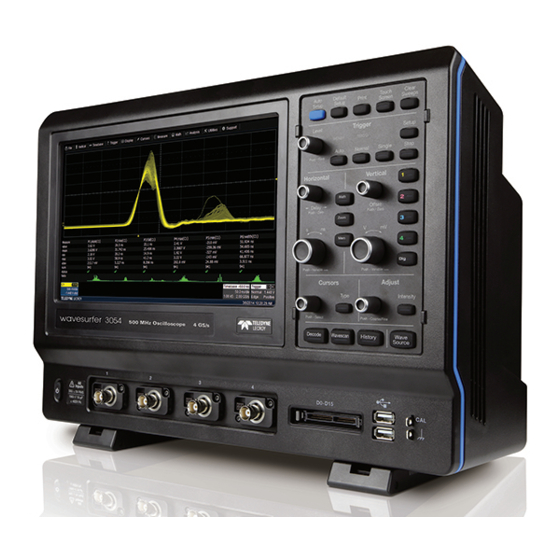
- Page 1 Operator's Manual WaveSurfer 3000 Oscilloscopes...
- Page 2 However, clients are encouraged to distribute and duplicate Teledyne LeCroy documentation for their own internal educational purposes. WaveSurfer and Teledyne LeCroy are trademarks of Teledyne LeCroy, Inc. Other product or brand names are trademarks or requested trademarks of their respective holders. Information in this publication supersedes all earlier versions.
-
Page 3: Table Of Contents
Operator's Manual Contents Safety Instructions Symbols Precautions Operating Environment Cooling Power Start Up Setting Up the Oscilloscope Powering On/Off Software Activation Inputs/Outputs Front Input/Output Panel Back Input/Output Panel Analog Inputs Probes Digital Inputs Touch Screen Menu Bar Signal Display Grid Descriptor Boxes Dialogs Shortcut Toolbar... - Page 4 WaveSurfer 3000 Oscilloscopes Zooming Waveforms Create Zoom Rescale Zoom Quick Zoom Turn Off Zoom Rescale Memory or Math Traces Zoom Controls Vertical Vertical Settings Probe Dialog Digital (Mixed Signal) Digital Traces Digital Group Set Up Digital Display Set Up Renaming Digital Lines...
- Page 5 Print to Notebook Entry Flashback Recall Configure LabNotebook Preferences Maintenance Cleaning Fuse Replacement Calibration Reboot Oscilloscope Adding an Option Key WaveSurfer 3000 Firmware Update Technical Support Returning a Product for Service Certifications EMC Compliance Safety Compliance Environmental Compliance ISO Certification Warranty...
- Page 6 WaveSurfer 3000 Oscilloscopes Welcome Thank you for purchasing a Teledyne LeCroy WaveSurfer Oscilloscope. We're certain you'll be pleased with the detailed features unique to our instruments. The manual is arranged in the following manner: Safety contains important precautions and information relating to power and cooling.
-
Page 7: Safety Instructions
Operator's Manual Safety Instructions Observe these instructions to keep the instrument operating in a correct and safe condition. You are required to follow generally accepted safety procedures in addition to the precautions specified in this section. The overall safety of any system incorporating this instrument is the responsibility of the assembler of the system. -
Page 8: Operating Environment
WaveSurfer 3000 Oscilloscopes Operating Environment Temperature: 0 to 50° C. Humidity: Maximum relative humidity 90 % for temperatures up to 31° C, decreasing linearly to 50% relative humidity at 40° C. Altitude: Up to 3,048 m (10,000 ft) at or below 30° C. - Page 9 Operator's Manual Ground The AC inlet ground is connected directly to the frame of the instrument. For adequate protection again electric shock, connect to a mating outlet with a safety ground contact. WARNING. Only use the power cord provided with your instrument. Interrupting the protective conductor inside or outside the oscilloscope, or disconnecting the safety ground terminal, creates a hazardous situation.
-
Page 10: Start Up
WaveSurfer 3000 accepts DHCP network addressing. Connect a cable from either Ethernet port on the back panel to a network access device. Go to Utilities > Utilities Setup > Remote and select TCPIP to obtain a network connection and IP address. -
Page 11: Powering On/Off
XTERNAL ONITOR WaveSurfer 3000 supports external monitors with 1024 x 600 ppi resolution. Connect the monitor cable to the VGA video output on the back of the instrument. The connection is “plug-and-play” and does not require any further configuration on the oscilloscope. If necessary, configure the monitor to receive output. -
Page 12: Software Activation
The oscilloscope operating software (firmware and standard applications) is active upon delivery. At power-up, the oscilloscope loads the software automatically. Firmware Free firmware updates are available periodically from the Teledyne LeCroy website at: teledynelecroy.com/support/softwaredownload. Registered users can receive an email notification when a new update is released. Follow the instructions on the website to download and install the software. -
Page 13: Inputs/Outputs
Operator's Manual Inputs/Outputs Front Input/Output Panel A. The Power button B. BNC connectors for analog input on Channels 1–4 (or 1–2 depending on model). C. Mixed signal interface for digital inputs (WS3K-MSO required). D. Two (2) front-mounted host USB ports for transferring data or connecting peripherals such as a mouse or keyboard. -
Page 14: Analog Inputs
Probes WaveSurfer3000 oscilloscopes are compatible with the included passive probes and all Teledyne LeCroy ProBus active probes that are rated for the oscilloscope’s bandwidth. Probe specifications and documentation are available at teledynelecroy.com/probes. -
Page 15: Digital Inputs
Operator's Manual Digital Inputs Available with the WS3K-MSO option, the digital leadset enables input of up-to-16 lines of digital data. Lines can be organized into two logical groups and renamed appropriately. The digital leadset features two digital banks with separate Threshold controls, making it possible to simultaneously view data from different logic families. -
Page 16: Touch Screen
WaveSurfer 3000 Oscilloscopes Touch Screen The touch screen is the principal viewing and control center of the oscilloscope. The entire display area is active: use your finger or a stylus to touch, touch-and-drag, or draw a selection box. Many controls that display information also work as “buttons”... -
Page 17: Signal Display Grid
Operator's Manual Signal Display Grid The grid area displays the waveform traces. It is sectioned into 10 Horizontal (Time) divisions and 8 Vertical (Voltage) divisions. By default, the oscilloscope divides the screen into a maximum of three grids, one each for channels/memories, math functions, and zooms. -
Page 18: Descriptor Boxes
WaveSurfer 3000 Oscilloscopes Trigger Level - This small triangle at the right edge of the grid tracks the trigger voltage level. If you change the trigger level when in Stop trigger mode, or in Normal or Single mode without a valid trigger, a hollow triangle of the same color appears at the new trigger level. - Page 19 Operator's Manual Channel Descriptor Box Channel trace descriptor boxes correspond to analog signal inputs. They show Vertical settings and any Vertical cursor readouts: (clockwise from top left) Trace Number (Cx), Pre-Processing List (summarizes changes from default state), Coupling, Gain Setting, Offset Setting, and Averaging Sweeps Count. Codes are used to indicate pre-processing that has been applied to the input.
-
Page 20: Dialogs
WaveSurfer 3000 Oscilloscopes Dialogs Dialogs appear at the bottom of the display for entering setup data. The top dialog will be the main entry point for the selected setup option. For convenience, related dialogs appear as a series of tabs behind the main dialog. Touch the tab to open the dialog. - Page 21 Operator's Manual In other cases, data entry fields appear highlighted in blue when you touch them. When a data entry field is highlighted, it is active and can be modified by using the front panel Adjust knob. Or, touch it again and use the pop-up menu or keypad to make an entry.
-
Page 22: Annotating Traces
WaveSurfer 3000 Oscilloscopes Annotating Traces The Label function gives you the ability to add custom annotations to traces that are shown on the display. Labels are numbered sequentially in the order they were created. Once placed, labels can be moved to new positions or turned off. -
Page 23: Printing
Operator's Manual Printing The Print function captures an image of the display and outputs it according to your Hardcopy settings: send to a printer, e-mail, or save to a file. There are three ways to print: Touch the front panel Print button. Choose File >... -
Page 24: Front Panel
WaveSurfer 3000 Oscilloscopes Front Panel Most front panel controls duplicate functionality available through the touch screen display and are described on the following pages. All the knobs on the front panel function one way if turned and another if pushed like a button. The top label describes the knob’s “turn” action, the bottom label its “push”... -
Page 25: Horizontal Controls
Operator's Manual Horizontal Controls The Delay knob changes the Trigger Delay value (S) when turned. Push the knob to reset Delay to zero. The Horizontal Adjust knob sets the Time/division (S) of the oscilloscope acquisition system when the trace source is an input channel. -
Page 26: Adjust And Intensity Controls
WaveSurfer 3000 Oscilloscopes Adjust and Intensity Controls The Adjust knob changes the value in any highlighted data entry field when turned. Pushing the Adjust knob toggles between coarse (large increment) or fine (small increment) adjustments when the knob is turned. -
Page 27: Turning On/Off Traces
Operator's Manual Turning On/Off Traces Analog Trace From the display, choose Vertical > Channel <#> Setup to turn on the trace. To turn it off, clear the Trace On checkbox on the corresponding Channel dialog. From the front panel, press the Channel button (1-4) to turn on the trace; press again to turn it off. NOTE: The default is to display each trace type in its own grid automatically (e.g., Channels together, Zooms together, Functions together). -
Page 28: Viewing Status
Access the Status dialogs by choosing the Status option from the Vertical, Timebase, Trigger, or Math menus (e.g., Channel Status, Acquisition Status). Zooming Waveforms The Zoom function magnifies a selected region of a trace. On WaveSurfer 3000 model oscilloscopes, you can display up-to-four zoom traces. Create Zoom To create a zoom, touch-and-drag to draw a selection box around any part of the source waveform. -
Page 29: Rescale Zoom
Operator's Manual The selected portion is resized to fit the full width of the grid. The degree of magnification, therefore, depends on the size of the rectangle that you draw. New zooms are turned on and visible by default. However, you can turn off a particular zoom if the display becomes too crowded, and the zoom settings are saved in its location, ready to be turned on again when desired. -
Page 30: Zoom Controls
WaveSurfer 3000 Oscilloscopes Zoom Controls Once the zoom trace has been created, use the controls on the Zx dialogs to adjust its Horizontal Scale to further "zoom" in or out. To access the dialogs, touch twice on any zoom trace descriptor box, or choose Math > Zoom Setup from the menu bar. -
Page 31: Vertical
The valid range depends on the current timebase setting. The Math deskew function performs the same activity. Probe Atten(uation) enables you to set probe attenuation manually if using a third-party probe. The oscilloscope's inputs automatically sense Teledyne LeCroy probes and sets probe attenuation and Vertical units for you. 923648 Rev A... -
Page 32: Probe Dialog
The Probe Dialog displays probe attributes and (depending on the probe type) allows you to AutoZero or DeGauss Teledyne LeCroy probes from the oscilloscope touch screen. When a probe is not connected, the Channel dialog shows only the C1 tab for vertical setup. -
Page 33: Digital (Mixed Signal)
Operator's Manual Digital (Mixed Signal) digital leadset (MSO) inputs up-to-16 lines of digital data. Leads are organized into two banks of eight leads each, and you assign each bank a standard Logic Family or a custom Threshold to capture the digital signals. The Digital set up dialog has two tabs each corresponding to one of two possible digital groups, labeled Digital1 to Digital2. -
Page 34: Digital Display Set Up
WaveSurfer 3000 Oscilloscopes NOTE: Each group can consist of anywhere from 1 to 16 of the leads that are (or will be) connected to signal, from either digital bank regardless of the Logic set on the bank. It does not matter if the some or all of the lines have been included in other groups. -
Page 35: Renaming Digital Lines
Operator's Manual Renaming Digital Lines The labels used to name each line can be changed to make the user interface more intuitive. Also, labels can be "swapped" between lines. Changing Labels Set up the digital group. 2. Touch Label and select from: Data - the default, which appends "D."... -
Page 36: Timebase
WaveSurfer 3000 Oscilloscopes Timebase Timebase, also known as Horizontal, settings control the trace along the X axis. These settings are shared by all channel traces. The time represented by each horizontal division of the grid, or Time/Division, is most easily adjusted using the front panel Horizontal knob. -
Page 37: Sampling Modes
Operator's Manual Sampling Modes Real Time Sampling Mode Real Time sampling mode is a series of digitized voltage values sampled on the input signal at a uniform rate. These samples are displayed as a series of measured data values associated with a single trigger event. By default, the waveform is horizontally positioned so that the trigger event is time zero on the grid. - Page 38 WaveSurfer 3000 Oscilloscopes EQUENCE When setting up Sequence Mode, you define the number of fixed-size segments acquired in single-shot mode (see the instrument specifications for the limits). The oscilloscope uses the sequence timebase setting to determine the capture duration of each segment. Along with this setting, the oscilloscope uses the number of segments, maximum segment length, and total available memory to determine the actual number of samples or segments, and time or points.
-
Page 39: Auto Setup
Operator's Manual Auto Setup Auto Setup quickly configures the essential oscilloscope settings based on the first input signal it finds, starting with Channel 1. If nothing is connected to Channel 1, it searches Channel 2 and so forth until it finds a signal. Vertical Scale (V/div), Offset, Timebase (Time/div), and Trigger are set so that there is an Edge trigger on the first, non- zero-level amplitude, and the entire waveform is visible for at least 10 cycles over the 10 horizontal divisions. -
Page 40: Trigger
WaveSurfer 3000 Oscilloscopes Trigger While the oscilloscope is continuously sampling signal when it is turned on, it can only display up to its maximum memory in data samples. Triggers select an exact event/time in the waveform to display on the oscilloscope screen so that memory is not wasted on insignificant periods of the signal. -
Page 41: Trigger Types
Operator's Manual Trigger Types These are the trigger types available for selection. If the trigger is part of a subgroup (e.g., Smart), first choose the subgroup from among the basic types to display all the trigger options. Basic Triggers Edge triggers upon a achieving a certain voltage level in the positive or negative slope of the wave. Width triggers upon finding a positive- or negative-going pulse width when measured at the specified voltage level. -
Page 42: Trigger Settings
WaveSurfer 3000 Oscilloscopes Trigger Settings To access the Trigger setup dialogs, choose Trigger > Trigger Setup from the menu bar, or press the front panel Trigger Setup button. The dialogs you see and the options on them will vary depending on your trigger type selection. The main Trigger dialog contains settings that are required for most trigger types. -
Page 43: Trigger Holdoff
Operator's Manual Trigger Holdoff Holdoff is an additional condition that may be set for Edge and Pattern triggers. It can be expressed either as a period of time or an event count. Holdoff disables the trigger temporarily, even if the trigger conditions are met, until the holdoff conditions are also met. - Page 44 WaveSurfer 3000 Oscilloscopes Edge trigger with holdoff by events. Holdoff Settings To access the Trigger Holdoff dialog, choose Triggers > Trigger Setup from the menu bar or press the front panel Trigger Setup button, then touch the Holdoff tab. Choose to Holdoff by Time (clock) or Event. None disables Holdoff.
-
Page 45: Display
Operator's Manual Display Display settings affect the number and style of grids that appear on screen and some of the visual characteristics of traces, such as persistence. To access the Display dialogs, choose Display > Display Setup or Display > Persistence Setup. Display settings affect the number and style of grids that appear on screen and some of the visual characteristics of traces, such as persistence. -
Page 46: Persistence Overview
WaveSurfer 3000 Oscilloscopes Persistence Overview The Persistence feature retains waveform traces on the display for a set amount of time before allowing them to gradually "decay," similar to the display of old phosphor screen oscilloscopes. Use Persistence to accumulate on- screen points from many acquisitions to see your signal change over time. -
Page 47: Cursors
Operator's Manual Cursors Cursors are markers (lines or cross-hairs) that identify specific voltage and time values on the waveform. Use cursors to make fast, accurate measurements of specific points in the waveform. There are five, standard cursor types available. Vertical (amplitude) cursor readouts appear the descriptor box for the trace; Horizontal (time) cursor readouts appear below the Timbebase descriptor box. -
Page 48: Cursor Settings
WaveSurfer 3000 Oscilloscopes Cursor Settings Display Cursors Use either of the following methods to quickly turn on/off cursors: From the menu bar, choose Cursors then select the desired cursor type from the drop-down list. On the front panel, press the Cursor Type button repeatedly to scroll through all the cursor types. Stop when the... -
Page 49: Measure
Operator's Manual Measure Measurement parameters are tools that give you access to a wide range of waveform properties. Use them to analyze many attributes of your waveform such as rise-time, rms voltage, and peak-to-peak voltage. The oscilloscope offers a selection of standard horizontal and vertical measurement parameters, as well as specialized parameters installed with optional software packages. - Page 50 WaveSurfer 3000 Oscilloscopes Viewing Statistics You can add the statistical measures value(last), mean, min., max., sdev, and num(ber of measurements computed) to the measurement parameter readout table. To turn on statistics, access the Measure dialog and check Statistics On. Clear the checkbox to remove statistics from the readout.
-
Page 51: List Of Standard Measurement Parameters
Operator's Manual List of Standard Measurement Parameters NOTE: There may be additional parameters available depending on the software options installed on the oscilloscope. Parameter Description Measures the difference between upper and lower levels in two-level signals. Differs from pkpk in that noise, Amplitude overshoot, undershoot, and ringing do not affect the measurement. - Page 52 WaveSurfer 3000 Oscilloscopes Parameter Description Phase difference between signal analyzed and signal used as reference. Both signals are measured from the Phase 50% point of their rising edges. Duration of pulse waveform's rising transition from 20% to 80% of the amplitude averaged for all rising Rise 20-80% transitions between the measurement gates.
-
Page 53: Quick Measurements
Operator's Manual Quick Measurements Once you have set up custom parameters in an available location, you can quickly hide or display them by choosing Measure > Measure Setup and checking the Show Table box. You do not have to go through the entire setup process. Table of measurements open beneath grid. - Page 54 WaveSurfer 3000 Oscilloscopes Determining Rise and Fall Times Once top and base are estimated, calculation of the rise and fall times is easily done (see figure). The appropriate threshold levels are automatically determined by the instrument, using the amplitude (ampl) parameter.
-
Page 55: Math
Operator's Manual Math Math traces (F1-F2) display the result of applying a mathematical operation to a source trace. The output of a math function is always another trace, whereas the output of a measurement parameter is a tabular readout of the measurement. - Page 56 WaveSurfer 3000 Oscilloscopes any other traces. Enable/Disable Math Function Once a math function has been created and saved in one of the Fx locations, just use the main Math dialog to quickly enable/disable it. Touch the front panel Math button, or from the menu bar, choose Math > Math Setup, then check the On box next to each function you wish to display.
-
Page 57: List Of Standard Math Functions
Operator's Manual List of Standard Math Functions NOTE: Additional math functions may be available depending on the options installed on the oscilloscope. Function Definition Absolute For every point in the waveform the distance away from zero is calculated. For values greater than zero this is the same as the value. -
Page 58: Trend Function
WaveSurfer 3000 Oscilloscopes Function Definition Trend Produces a waveform composed of a series of parameter measurements in the order the measurements were taken. The vertical units are those of the source parameter, the horizontal unit is measurement number. The trend contains a single value for each measurement. -
Page 59: Rescaling And Assigning Units
Operator's Manual Rescaling and Assigning Units This feature allows you to apply a multiplication factor (a) and additive constant (b) to your waveform: aX + b. You can do it in the unit of your choice, depending on the type of application. Set Up Rescaling 1. - Page 60 WaveSurfer 3000 Oscilloscopes Abbreviated Units of Measure Abbreviation Measure Abbreviation Measure (blank) No units Newton Ampere Coulomb Pascal CYCLE Cycles Percent Decibel POISE Poise Decibel referred to carrier Parts per million Decibel Milliwatt Radian Decibel Volts Degree (of arc) DBUZ...
-
Page 61: Averaging Waveforms
Operator's Manual Averaging Waveforms Summed Averaging Summed Averaging is the repeated addition, with equal weight, of successive source waveform records. If a stable trigger is available, the resulting average has a random noise component lower than that of a single-shot record. Whenever the maximum number of sweeps is reached, the averaging process stops. -
Page 62: Fft
WaveSurfer 3000 Oscilloscopes Set Up Averaging To quickly set up Continuous Averaging (only), access the Channel setup dialog and enter the number of sweeps to average in Averaging. The valid range is 1 to 1,000,000 sweeps. To apply Continuous or Summed Averaging as a Math function: 1. - Page 63 Operator's Manual 5. Optionally, choose a weighting Window. See the section below for more information about FFT weighting windows. 6. Depending on your Output Type selection, you may also make selections for : Group Delay Shift Line Impedence. By default, the FFT function assumes that the oscilloscope is terminated in 50 Ohms. If an external terminator is being used, this setting can be changed to properly calculate the FFT based on the new termination value.
-
Page 64: Memory
Zoom controls that appear next to the Mx dialogs. Trace (.trc) files saved on other Teledyne LeCroy oscilloscopes can also be stored to the removable MicroSD card. Use Recall Waveform function to save external files to memory. Save Waveform to Memory 1. -
Page 65: Analysis
Operator's Manual Analysis Most Teledyne LeCroy oscilloscopes calculate measurements for all instances in the acquisition, enabling you to rapidly and thoroughly analyze a long memory acquisition of thousands or millions of parameter values to find anomalous measurements, or to apply a variety of mathematical functions to the waveform trace. - Page 66 WaveSurfer 3000 Oscilloscopes Scan Modes The scan mode determines the type of search to be performed. Select the Mode along with the Source trace to be searched on the main WaveScan dialog. For each mode, different controls appear on the WaveScan dialog, providing additional inputs to the search criteria.
- Page 67 Operator's Manual EASUREMENT Measurement Mode is used for applying filters to measurements to find those that meet your defined criteria, helping to isolate particular events within many samples. Markers appear over the source trace to indicate the location of measurement, while the table displays values for the selected parameter that meet the criteria. Additional Settings for Measurement Mode are: Measurement.
- Page 68 WaveSurfer 3000 Oscilloscopes Set Up WaveScan This procedure explains how to set up WaveScan to search an acquisition for events of interest. Set up your source channel and triggers before setting up the scan. 1. Press the front panel Stop button to stop acquisition.
-
Page 69: History Mode
Operator's Manual History Mode History Mode allows you to review any acquisition saved in the oscilloscope's history buffer, which automatically stores all acquisition records until full. Not only can individual acquisitions be restored to the grid, you can "scroll" backward and forward through the history at varying speeds to capture individual details or changes in the waveforms over time. -
Page 70: Utilities
The Service button to the far right of the dialog (not shown) launches a section of the application reserved for qualified Teledyne LeCroy service personnel. An access code is required to enter this section. System Status The Utilities Status dialog displays information about your instrument including model number, serial number, firmware version, and installed hardware and software options. -
Page 71: Remote Control Settings
The Remote dialog contains settings to configure remote control of the instrument. Supported protocols are: TCPIP (Ethernet). If you choose this option, also install Teledyne LeCroy's VICP drivers on the controller. These are included in the VICP Passport plug-in, available free from teledynelecroy.com. The instrument uses Dynamic Host Configuration Protocol (DHCP) as its addressing protocol. -
Page 72: Hardcopy Settings
Follow these steps to configure output to a printer. To print immediately, touch the Print Now button at the far right of the dialog. NOTE: WaveSurfer 3000 oscilloscopes support PictBridge-compatible printers. Printers can be connected via LAN (Ethernet) or USB. - Page 73 Operator's Manual 5. Optionally, enter the path to a new save Directory (the default folder is \Hardcopy), or touch the Browse button and navigate to the folder. 6. Optionally, choose a color scheme and hardcopy (print) area. Send to E-Mail Follow this procedure to e-mail capture files to a preset address.
-
Page 74: Aux Output Settings
WaveSurfer 3000 Oscilloscopes Aux Output Settings The Aux Out port on the back of the oscilloscope outputs a 3.3V TTL pulse to another device following a trigger event. Use the Aux Output dialog to configure the calibration signal output from the Cal Out hook on the front of the oscilloscope. -
Page 75: Date/Time Settings
Operator's Manual Date/Time Settings Date/Time settings control the oscilloscope's timestamp. These numbers appear in the oscilloscope message bar and on tables/records internal to the oscilloscope application, such as History Mode and WaveScan. NOTE: This is not the same as the Timebase reference clock used to synchronize traces. To access the Date/Time dialog, choose Utilities >... -
Page 76: Preferences Settings
WaveSurfer 3000 Oscilloscopes Preferences Settings Preference settings have mostly to do with the appearance and performance of the oscilloscope itself, rather than the oscilloscope's interaction with other devices/systems. Access the Preferences dialog by choosing Utilities > Preference Setup... from the menu bar. -
Page 77: Calibration Settings
Operator's Manual Calibration Settings To ensure the instrument maintains specified performance, it is factory set to perform a calibration during warm-up. We recommend that you warm up the oscilloscope for at least 20 minutes prior to use to give the instrument time to complete calibration procedures. -
Page 78: Acquisition Settings
WaveSurfer 3000 Oscilloscopes Acquisition Settings The Acquisition settings determine how traces behave on screen as gain or timebase changes. Offset Setting constant in: Volts moves the vertical offset level indicator with the actual voltage level. Div(isions) keeps the vertical offset level indicator stationary. The waveform remains on the grid as you increase the gain;... -
Page 79: Miscellaneous Settings
Miscellaneous Settings These other Preference settings are located on the Miscellaneous dialog. To add the Teledyne LeCroy logo to print output, check Print Teledyne LeCroy Logo When Printing Grid Area Only. This identifies the instrument as the source of the image. -
Page 80: Wavesource Automatic Waveform Generator
The WaveSource Automatic Waveform Generator allows you to output custom sine, square, triangle, pulse, DC and noise waveforms from the WaveSurfer 3000. Connect a BNC cable from the WaveSource output on the back of the oscilloscope to the input device. -
Page 81: Save/Recall
Operator's Manual Save/Recall The oscilloscope File menu allows you to save or retrieve waveform files, measurement table data, and instrument setup panels. Access these functions by choosing any of the Save or Recall options from the File menu. The dialog contains a tab for each file function. -
Page 82: Save/Recall Waveforms
WaveSurfer 3000 Oscilloscopes Recalling Oscilloscope Setups Choose File > Recall Setup... from the menu bar. ECALL ETUP EMORY Touch one of the six Recall buttons under Recall From Internal Setup..NOTE: If a setup has been stored to a location, it is labeled with the save date/time. Otherwise, the slot is labeled Empty. - Page 83 Place numbers at the beginning, or place an alpha character after the number (e.g., XYZ32a). 4. Touch Data Format and select a file format: Binary, Teledyne LeCroy's binary file format (.trc). Binary results in the smallest possible file size, and is necessary for recalling waveforms to Teledyne LeCroy instruments.
- Page 84 WaveSurfer 3000 Oscilloscopes Recall Waveform Choose File > Recall Waveform from the menu bar. NOTE: Only .trc files saved in binary format can be recalled into the oscilloscope. ECALL AVEFORM EMORY 1. Touch Memory. 2. Touch Source and choose a memory location from the Select Source pop-up.
-
Page 85: Save Table Data
Operator's Manual Save Table Data The Save Table function saves tabular measurement data displayed on screen to an Excel or ASCII file. By default, files are saved on the MicroSD card, although you can choose a USB drive. Access the Save Table dialog by choosing File > Save Table from the menu bar. 1. -
Page 86: Disk Utilities
WaveSurfer 3000 Oscilloscopes Disk Utilities Use the Disk Utilities dialog to manage files and folders on your instrument's hard drive. Disk Space information is shown at the far right of the dialog for convenience. Access the Disk Utilities dialog by selecting Utilities > Disk Utilities from the menu bar, or choose any of the Save/Recall functions and open the Disk Utilities tab. -
Page 87: Labnotebook
Operator's Manual LabNotebook Teledyne LeCroy's LabNotebook feature extends the documentation capabilities of your oscilloscope. It allows you to create and save Notebook Entries containing all displayed waveforms, the oscilloscope setup under which they were taken, and custom annotations. Notebook Entries are stored in an internal database and are available for recall at any time. Besides storing the waveform data, LabNotebook also stores your panel setups and parameter measurements. -
Page 88: Flashback Recall
WaveSurfer 3000 Oscilloscopes Flashback Recall Once a Notebook Entry is made, you can recall it at any time using Flashback Recall. The recall includes waveforms and oscilloscope settings, so you can analyze the inputs that resulted in that capture. 1. Choose File > LabNotebook to open the LabNotebook dialog. -
Page 89: Maintenance
Operator's Manual Maintenance Cleaning Clean only the exterior of the instrument using a soft cloth moistened with water or an alcohol solution. Do not use harsh chemicals or abrasive elements. Under no circumstances submerge the instrument or allow moisture to penetrate it. Avoid electric shock by unplugging the power cord from the AC outlet before cleaning. -
Page 90: Adding An Option Key
Many optional software packages are available to extend the Analysis functions of the oscilloscope. See the product page at teledynelecroy.com for a list of options compatible with your model. Contact your local Teledyne LeCroy representative or national distributor to purchase an option. You will receive a Key Code by email that enables the new functionality. -
Page 91: Technical Support
Technical Support requests by phone or email. Teledyne LeCroy publishes a free Technical Library on its website. Manuals, tutorials, application notes, white papers, and videos are available to help you get the most out of your Teledyne LeCroy products. -
Page 92: Returning A Product For Service
4. Pack the product case in a cardboard shipping box with adequate padding to avoid damage in transit. 5. Mark the outside of the box with the shipping address given to you by Teledyne LeCroy; be sure to add the following: ATTN: <RMA code assigned by Teledyne LeCroy>... - Page 93 Protocol Analyzers: FAX: ++ 81 4 2402 9586 Ph: +44 12 765 03971 teledynelecroy.com/japan Singapore, Oscilloscopes Teledyne LeCroy Singapore Pte Ltd. Blk 750C Chai Chee Road #02-08 Technopark @ Chai Chee Singapore 469003 Ph: ++ 65 64424880 FAX: ++ 65 64427811...
-
Page 94: Certifications
WaveSurfer 3000 Oscilloscopes Certifications EMC Compliance EC Declaration of Conformity- EMC The oscilloscope meets intent of EC Directive 2004/108/EC for Electromagnetic Compatibility. Compliance was demonstrated to the following specifications as listed in the Official Journal of the European Communities: EN 61326-1:2013, EN 61326-2-1:2013 EMC requirements for electrical equipment for measurement, control, and laboratory use. -
Page 95: Safety Compliance
Operator's Manual Australia & New Zealand Declaration of Conformity– EMC Oscilloscope complies with the EMC provision of the Radio Communications Act per the following standards, in accordance with requirements imposed by Australian Communication and Media Authority (ACMA): EN 55011:2010 Radiated and Conducted Emissions, Group 1, Class A, in accordance with EN61326-1:2013 and EN61326-2-1:2013. -
Page 96: Environmental Compliance
The product is warranted for normal use and operation, within specifications, for a period of three years from shipment. Teledyne LeCroy will either repair or, at our option, replace any product returned to one of our authorized service centers within this period. However, in order to do this we must first examine the product and find that it is defective due to workmanship or materials and not due to misuse, neglect, accident, or abnormal conditions or operation.