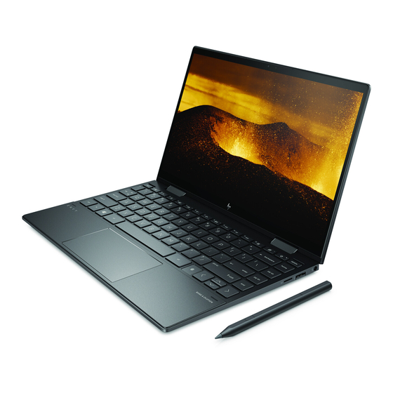
HP ENVY x360 13 Maintenance And Service Manual
13-ag0 series.
convertible pc
Hide thumbs
Also See for ENVY x360 13:
- Maintenance and service manual (77 pages) ,
- Maintenance and service manual (93 pages) ,
- Maintenance and service manual (90 pages)

Related Manuals for HP ENVY x360 13


Summary of Contents for HP ENVY x360 13
- Page 1 HP ENVY x360 13 Convertible PC Maintenance and Service Guide IMPORTANT! This document is intended for HP authorized service providers only.
- Page 2 Intel, Core, and Pentium are U.S. registered bound by the terms of the HP End User License Not all features are available in all editions of trademarks of Intel Corporation. Microsoft and Agreement (EULA).
- Page 3 Safety warning notice WARNING! To reduce the possibility of heat-related injuries or of overheating the device, do not place the device directly on your lap or obstruct the device air vents. Use the device only on a hard, flat surface. Do not allow another hard surface, such as an adjoining optional printer, or a soft surface, such as pillows or rugs or clothing, to block airflow.
- Page 4 Safety warning notice...
-
Page 5: Table Of Contents
Table of contents 1 Product description ............................1 2 Getting to know your computer ........................4 Right side ................................4 Left side ................................. 5 Display ..................................6 Keyboard area ................................ 7 TouchPad ............................. 7 Lights ..............................8 Speakers .............................. 9 Special keys ............................ - Page 6 Using HP PC Hardware Diagnostics UEFI ......................56 Starting HP PC Hardware Diagnostics UEFI ..................57 Downloading HP PC Hardware Diagnostics UEFI to a USB flash drive ..........57 Downloading the latest HP PC Hardware Diagnostics UEFI version ......57 Downloading HP PC Hardware Diagnostics UEFI by product name or number (select products only) .....................
- Page 7 Using HP Recovery Manager to create recovery media ..............61 Before you begin ......................61 Creating the recovery media ................... 61 Using the HP Cloud Recovery Download Tool to create recovery media .......... 62 Restoring and recovery ............................62 Restoring, resetting, and refreshing using Windows tools .............. 62 Restoring using HP Recovery Manager and the HP Recovery partition ...........
- Page 8 viii...
-
Page 9: Product Description
Product description Category Description Product Name HP ENVY x360 13 Convertible PC Model numbers: 13-ag0000 ~ 13-ag0999 CTO model: 13z-ag000 Processors AMD® Ryzen™ mobile processors: AMD Ryzen 7 2700U Mobile Processor (2.2 GHz, turbo up to 3.8 GHz, 2-MB L2 + 4 GB L3 cache, 2400 MHz, quad core, 15 W) with Radeon RX Vega 10 Graphics AMD Ryzen 5 2500U Mobile Processor (2.0 GHz, turbo up to 3.6 GHz, 2-MB L2 + 4 GB L3 cache, 2400 MHz, quad... - Page 10 128-GB, SATA-3, TLC Camera HP Wide Vision HD IR Camera, indicator LED & 2x IR LEDs, USB2.0, HD BSI sensor + IR sensor, f2.2, WDR, 88° WFOV 720p by 30 frames per second Dual array digital microphone w/ appropriate software - beam forming, echo cancellation, noise suppression...
- Page 11 AC adapter: 65-W HP Smart AC adapter, nPFC, slim black barrel, straight, 4.5 mm 65-W HP Smart AC adapter, nPFC, slim black barrel, straight, 4.5 mm - EM 45-W HP Smart AC adapter, nPFC, wall-mount barrel, right angle, 4.5 mm Power cord: 1.0 m premium power cord (C5)
-
Page 12: Getting To Know Your Computer
Component Description Volume button Controls speaker volume on the computer. USB Type-C port with HP Sleep and Charge Connects an AC adapter that has a USB Type-C connector, supplying power to the computer and, if needed, charging the computer battery. -
Page 13: Left Side
For additional safety information, refer to the Regulatory, Safety, and Environmental Notices. To access this guide: Select the Start button, select HP Help and Support, and ▲ then select HP Documentation. NOTE: When a device is connected to the jack, the computer speakers are disabled. -
Page 14: Display
For wireless regulatory notices, see the section of the Regulatory, Safety, and Environmental Notices that applies to your country or region. To access this guide: Type support in the taskbar search box, and then select the HP Support Assistant app. ‒ or – Click the question mark icon in the taskbar. -
Page 15: Keyboard Area
Keyboard area TouchPad Component Description TouchPad zone Reads your finger gestures to move the pointer or activate items on the screen. Left TouchPad button Functions like the left button on an external mouse. Right TouchPad button Functions like the right button on an external mouse. Keyboard area... -
Page 16: Lights
Lights Component Description Caps lock light On: Caps lock is on, which switches the key input to all capital letters. Mute light ● On: Computer sound is off. ● Off: Computer sound is on. Chapter 2 Getting to know your computer... -
Page 17: Speakers
Speakers Component Description Speakers Produce sound. Keyboard area... -
Page 18: Special Keys
Special keys Component Description Displays system information when pressed in combination with key. Executes specific functions when pressed in combination with another key. Windows key Opens the Start menu. NOTE: Pressing the Windows key again will close the Start menu. Action keys Execute frequently used system functions. -
Page 19: Action Keys
Action keys An action key performs the function indicated by the icon on the key. To determine which keys are on your product, see Special keys on page ▲ To use an action key, press and hold the key. Icon Description Helps prevent side-angle viewing from onlookers. -
Page 20: Bottom
Bottom Component Description Speakers Produce sound. Vent Enables airflow to cool internal components. NOTE: The computer fan starts up automatically to cool internal components and prevent overheating. It is normal for the internal fan to cycle on and off during routine operation. -
Page 21: Labels
Your service label will resemble one of the examples shown below. Refer to the illustration that most closely matches the service label on your computer. Component HP product name (select products only) Model number Product ID Serial number... - Page 22 Component Serial number Warranty period ● Regulatory label(s)—Provide(s) regulatory information about the computer. ● Wireless certification label(s)—Provide(s) information about optional wireless devices and the approval markings for the countries or regions in which the devices have been approved for use. Chapter 2 Getting to know your computer...
-
Page 23: Illustrated Parts Catalog
Illustrated parts catalog NOTE: HP continually improves and changes product parts. For complete and current information on supported parts for your computer, go to http://partsurfer.hp.com, select your country or region, and then follow the on-screen instructions. Computer components Computer components... - Page 24 Item Component Spare part number Display assembly IMPORTANT: The display assembly is only spared as an entire hinge-up. Display subcomponents are not spared. FHD, anti glare, privacy L19576-001 HD, BrightView, non-privacy L19577-001 UHD, BrightView, non-privacy L19578-001 Power button L28981-001 Top cover with backlit keyboard Non-privacy L19586-xx1 Privacy...
-
Page 25: Foil Kit
Item Component Spare part number xxxxxx-601: Windows operating system Ryzen 7 2700U processor and 8 GB system memory L26110-xx1 Ryzen 5 2500U processor and 16 GB system memory L19574-xx1 Ryzen 5 2500U processor and 8 GB system memory L19573-xx1 Ryzen 3 2300U processor and 8 GB system memory L19572-xx1 Ryzen 3 2300U processor and 4 GB system memory L19571-xx1... -
Page 26: Miscellaneous Parts
AC adapter, 65-W HP Smart AC adapter (non-PFC, 4.5-mm) 913691-850 AC adapter, 45-W HP Smart AC adapter (non-PFC, RC, 4.5-mm) 854116-850 AC adapter, 45-W HP Smart AC adapter (non-PFC, RC, 4.5-mm), for use only in LA MERCO L32926-001 Power cord (C5 connector, 1.0 m): For use in Argentina... - Page 27 Component Spare part number HP USB external DVD±RW drive 747080-001 Screw Kit L19603-001 Miscellaneous parts...
-
Page 28: Removal And Replacement Preliminary Requirements
Removal and replacement preliminary requirements Tools required You will need the following tools to complete the removal and replacement procedures: ● Non-marking plastic pry tool ● Phillips P0 screwdriver Phillips P1 screwdriver ● ● Torx T5 screwdriver Service considerations The following sections include some of the considerations that you must keep in mind during disassembly and assembly procedures. -
Page 29: Cables And Connectors
Cables and connectors CAUTION: When servicing the computer, be sure that cables are placed in their proper locations during the reassembly process. Improper cable placement can damage the computer. Cables must be handled with extreme care to avoid damage. Apply only the tension required to unseat or seat the cables during removal and insertion. -
Page 30: Grounding Guidelines
Grounding guidelines Electrostatic discharge damage Electronic components are sensitive to electrostatic discharge (ESD). Circuitry design and structure determine the degree of sensitivity. Networks built into many integrated circuits provide some protection, but in many cases, ESD contains enough power to alter device parameters or melt silicon junctions. A discharge of static electricity from a finger or other conductor can destroy static-sensitive devices or microcircuitry. -
Page 31: Packaging And Transporting Guidelines
Packaging and transporting guidelines Follow these grounding guidelines when packaging and transporting equipment: To avoid hand contact, transport products in static-safe tubes, bags, or boxes. ● ● Protect ESD-sensitive parts and assemblies with conductive or approved containers or packaging. Keep ESD-sensitive parts in their containers until the parts arrive at static-free workstations. ●... - Page 32 Equipment guidelines Grounding equipment must include either a wrist strap or a foot strap at a grounded workstation. ● When seated, wear a wrist strap connected to a grounded system. Wrist straps are flexible straps with a minimum of one megohm ±10% resistance in the ground cords. To provide proper ground, wear a strap snugly against the skin at all times.
-
Page 33: Removal And Replacement Procedures For Authorized Service Provider Parts
NOTE: HP continually improves and changes product parts. For complete and current information on supported parts for your computer, go to http://partsurfer.hp.com, select your country or region, and then follow the on-screen instructions. There are as many as 45 screws that must be removed, replaced, and/or loosened when servicing Authorized Service Provider only parts. - Page 34 Remove the two Torx T5 2.0×4.0 screws (3). Starting under the hinges, use a thin plastic tool (1) to pry the bottom cover off the computer (2). Remove the bottom cover (3). Reverse this procedure to install the bottom cover. Chapter 5 Removal and replacement procedures for Authorized Service Provider parts...
-
Page 35: Battery
Battery Description Spare part number 3-cell, 41-WHr, 3.6-AHr, Li-ion battery L08496-855 Before removing the battery, follow these steps: Shut down the computer. If you are unsure whether the computer is off or in Hibernation, turn the computer on, and then shut it down through the operating system. Disconnect all external devices connected to the computer. -
Page 36: Wlan Module
WLAN module Description Spare part number Intel Dual Band Wireless-AC 7265 802.11 AC 2×2 WiFi + Bluetooth 4.2 Combo Adapter (non-vPro) 901229-855 Realtek RTL8822BE 802.11 ac 2x2 WiFi + Bluetooth 4.2 Combo Adapter (MU-MIMO supported) 924813-855 Intel Dual Band Wireless AC-9260, 2x2 WiFi + Bluetooth 5.0 Combo Adapter (vPro) L16647-005 CAUTION: To prevent an unresponsive system, replace the wireless module only with a wireless module... - Page 37 Remove the WLAN module (3) by pulling the module away from the slot at an angle. NOTE: The WLAN module is designed with a notch to prevent incorrect insertion. Reverse this procedure to install the WLAN module. Component replacement procedures...
-
Page 38: Solid-State Drive
Solid-state drive Description Spare part number 1-TB, PCIe, TLC L19583-001 512-GB, PCIe, TLC L19582-001 512-GB, PCIe, value L19585-001 256-GB, PCIe, TLC L19580-001 256-GB, PCIe, value L19584-001 128-GB, SATA-3, TLC L19579-001 Solid-state drive Mylar shield L19790-001 (Foil Kit) Before removing the solid-state drive, follow these steps: Shut down the computer. - Page 39 Remove the module (3) by pulling it away from the connector. Reverse this procedure to iinstall a solid-state drive. Component replacement procedures...
-
Page 40: Memory Shield
Memory shield Description Spare part number Memory shield L19789-001 IMPORTANT: The memory is integrated into the system board and is not removable or upgradeable. Before removing the memory shield, follow these steps: Turn off the computer. If you are unsure whether the computer is off or in Hibernation, turn the computer on, and then shut it down through the operating system. - Page 41 Component replacement procedures...
-
Page 42: Display Assembly
Display assembly Description Spare part number Display assembly, FHD, anti glare, privacy L19576-001 Display assembly, HD, BrightView, non-privacy L19577-001 Display assembly, UHD, BrightView, non-privacy L19578-001 Before removing the display assembly, follow these steps: Shut down the computer. If you are unsure whether the computer is off or in Hibernation, turn the computer on, and then shut it down through the operating system. - Page 43 Rotate the hinges upward to about 90 degrees (2). Separate the display from the computer (3). Reverse this procedure to install the display assembly. Component replacement procedures...
-
Page 44: Top Speakers
Top speakers Description Spare part number Top speakers (include cable) L19601-001 Before removing the top speakers, follow these steps: Turn off the computer. If you are unsure whether the computer is off or in Hibernation, turn the computer on, and then shut it down through the operating system. Disconnect the power from the computer by first unplugging the power cord from the AC outlet, and then unplugging the AC adapter from the computer. - Page 45 Remove the speakers (5). IMPORTANT: When installing the speakers, make sure the rubber post washers (6) are correctly installed. Reverse this procedure to install the speakers. Component replacement procedures...
-
Page 46: Bottom Speakers
Bottom speakers Description Spare part number Bottom speakers (include cables) L19602-001 Before removing the bottom speakers, follow these steps: Turn off the computer. If you are unsure whether the computer is off or in Hibernation, turn the computer on, and then shut it down through the operating system. Disconnect the power from the computer by first unplugging the power cord from the AC outlet, and then unplugging the AC adapter from the computer. -
Page 47: Card Reader Board
Card reader board Description Spare part number Card reader board L19593-001 Card reader board cable L19598-001 Before removing the card reader board, follow these steps: Shut down the computer. If you are unsure whether the computer is off or in Hibernation, turn the computer on, and then shut it down through the operating system. -
Page 48: Touchpad
TouchPad Description Spare part number TouchPad L19594-001 TouchPad cable L19597-001 TouchPad bracket L19788-001 Before removing the TouchPad, follow these steps: Shut down the computer. If you are unsure whether the computer is off or in Hibernation, turn the computer on, and then shut it down through the operating system. Disconnect all external devices connected to the computer. - Page 49 Remove the TouchPad from the computer (4). Reverse this procedure to install the TouchPad. Component replacement procedures...
-
Page 50: Thermal Module
Thermal module NOTE: The thermal module assembly spare part kit includes replacement thermal material. Description Spare part number Thermal module (includes fan and heat sink) L19599-001 Before removing the thermal module, follow these steps: Turn off the computer. If you are unsure whether the computer is off or in Hibernation, turn the computer on, and then shut it down through the operating system. - Page 51 Remove the thermal module (5). NOTE: The thermal material must be thoroughly cleaned from the surfaces of the heat sink and the system board components each time the thermal module is removed. Replacement thermal material is included with the thermal module and system board spare part kits. Thermal paste is used on the system board component (1) and associated heat sink section (2).
- Page 52 Reverse this procedure to install the thermal module. Chapter 5 Removal and replacement procedures for Authorized Service Provider parts...
-
Page 53: Fan
Description Spare part number L23528-001 Before removing the fan, follow these steps: Turn off the computer. If you are unsure whether the computer is off or in Hibernation, turn the computer on, and then shut it down through the operating system. Disconnect the power from the computer by first unplugging the power cord from the AC outlet, and then unplugging the AC adapter from the computer. -
Page 54: System Board
System board NOTE: All system board spare part kits include a processor and replacement thermal material. All system boards use the following part numbers: xxxxxx-001: Non-Windows operating systems xxxxxx-601: Windows operating system Description Spare part number System board with integrated Ryzen 7 2700U processor and 8 GB system memory L26110-xx1 System board with integrated Ryzen 5 2500U processor and 16 GB system memory L19574-xx1... - Page 55 (9) Top speaker cable Lift the square shield from the system board (1). Remove the three Phillips M2.0×3.5 screws (2) that secure the fan to the computer. Remove the four Phillips M2.0×2.0 screws (3) that secure the system board to the computer. Lift the side of the system board up (4).
-
Page 56: Power Button
Power button Description Spare part number Power button L28981-001 Before removing the power button, follow these steps: Shut down the computer. If you are unsure whether the computer is off or in Hibernation, turn the computer on, and then shut it down through the operating system. Disconnect all external devices connected to the computer. -
Page 57: Volume Button
Volume button Description Spare part number Volume button L28982-001 Before removing the volume button, follow these steps: Shut down the computer. If you are unsure whether the computer is off or in Hibernation, turn the computer on, and then shut it down through the operating system. Disconnect all external devices connected to the computer. -
Page 58: Fingerprint Reader Module
Fingerprint reader module Description Spare part number Fingerprint reader module L23655-001 Before removing the fingerprint reader module, follow these steps: Turn off the computer. If you are unsure whether the computer is off or in Hibernation, turn the computer on, and then shut it down through the operating system. Disconnect the power from the computer by first unplugging the power cord from the AC outlet, and then unplugging the AC adapter from the computer. -
Page 59: Power Connector Cable
Power connector cable Description Spare part number Power connector cable L19588-001 Before removing the power connector cable, follow these steps: Shut down the computer. If you are unsure whether the computer is off or in Hibernation, turn the computer on, and then shut it down through the operating system. Disconnect all external devices connected to the computer. -
Page 60: Top Cover With Keyboard
Top cover with keyboard The top cover with keyboard remains after removing all other spared parts from the computer. In this section, the first table provides the main spare part number for the keyboards. The second table provides the country codes. Description Spare part number Top cover with backlit keyboard, non-privacy... -
Page 61: Using Setup Utility (Bios)
To reveal the BIOS version information (also known as ROM date and System BIOS), use one of these options. ● HP Support Assistant Type support in the taskbar search box, and then select the HP Support Assistant app. – or – Click the question mark icon in the taskbar. -
Page 62: Downloading A Bios Update
If your computer is connected to a network, consult the network administrator before installing any software updates, especially system BIOS updates. Type support in the taskbar search box, and then select the HP Support Assistant app. – or – Click the question mark icon in the taskbar. -
Page 63: Using Hp Pc Hardware Diagnostics
The tool runs within the Windows operating system in order to diagnose hardware failures. If HP PC Hardware Diagnostics Windows is not installed on your computer, first you must download and install it. To download HP PC Hardware Diagnostics Windows, see... -
Page 64: Downloading The Latest Hp Pc Hardware Diagnostics Windows Version
If your PC will not boot into Windows, you can use HP PC Hardware Diagnostics UEFI to diagnose hardware issues. -
Page 65: Starting Hp Pc Hardware Diagnostics Uefi
Downloading HP PC Hardware Diagnostics UEFI to a USB flash drive Downloading HP PC Hardware Diagnostics UEFI to a USB flash drive can be useful in the following situations: HP PC Hardware Diagnostics UEFI is not included in the preinstall image. -
Page 66: Using Remote Hp Pc Hardware Diagnostics Uefi Settings (Select Products Only)
Find out more. Downloading Remote HP PC Hardware Diagnostics UEFI NOTE: HP Remote PC Hardware Diagnostics UEFI is also available as a Softpaq that can be downloaded to a server. Downloading the latest Remote HP PC Hardware Diagnostics UEFI version To download the latest Remote HP PC Hardware Diagnostics UEFI version, follow these steps: Go to http://www.hp.com/go/techcenter/pcdiags. - Page 67 Make your customization selections. Select Main, and then Save Changes and Exit to save your settings. Your changes take effect when the computer restarts. Using Remote HP PC Hardware Diagnostics UEFI settings (select products only)
-
Page 68: Backing Up, Restoring, And Recovering
Creating HP Recovery media (select products only) After you have successfully set up the computer, use HP Recovery Manager to create a backup of the HP Recovery partition on the computer. This backup is called HP Recovery media. In cases where the hard drive is corrupted or has been replaced, the HP Recovery media can be used to reinstall the original operating system. -
Page 69: Using Hp Recovery Manager To Create Recovery Media
On select products, you can use the HP Cloud Recovery Download Tool to create HP Recovery media on a bootable USB flash drive. For more information, see Using the HP Cloud Recovery Download Tool to create recovery media on page... -
Page 70: Using The Hp Cloud Recovery Download Tool To Create Recovery Media
Recovering using HP Recovery Manager You can use HP Recovery Manager software to recover the computer to its original factory state by using the HP Recovery media that you either created or that you obtained from HP, or by using the HP Recovery partition (select products only). -
Page 71: Recovering Using The Hp Recovery Partition (Select Products Only)
Recovering using HP Recovery media If your computer does not have an HP Recovery partition or if the hard drive is not working properly, you can use HP Recovery media to recover the original operating system and software programs that were installed at the factory. -
Page 72: Changing The Computer Boot Order
Changing the computer boot order If your computer does not restart in HP Recovery Manager, you can change the computer boot order. This is the order of devices listed in BIOS where the computer looks for startup information. You can change the selection to an optical drive or a USB flash drive, depending on the location of your HP Recovery media. -
Page 73: Specifications
Specifications Metric U.S. Computer dimensions Width 306.7 mm 12.08 in Depth 214.6 mm 8.45 in Height 14.9 mm 0.59 in Weight 1301 g 2.87 lbs Temperature Operating 5°C to 35°C 41°F to 95°F Nonoperating ‑20°C to 60°C ‑4°F to 140°F Relative humidity (noncondensing) Operating 10% to 90%... -
Page 74: 10 Power Cord Set Requirements
10 Power cord set requirements The wide-range input feature of the computer permits it to operate from any line voltage from 100 to 120 volts AC, or from 220 to 240 volts AC. The 3-conductor power cord set included with the computer meets the requirements for use in the country or region where the equipment is purchased. - Page 75 Country/region Accredited agency Applicable note number South Korea Sweden CEMKO Switzerland Taiwan BSMI The United Kingdom The United States The flexible cord must be Type HO5VV-F, 3-conductor, 1.0-mm² conductor size. Power cord set fittings (appliance coupler and wall plug) must bear the certification mark of the agency responsible for evaluation in the country or region where it will be used. The flexible cord must be Type SPT-3 or equivalent, No.
-
Page 76: 11 Recycling
Follow the local laws and regulations in your area for battery disposal. HP encourages customers to recycle used electronic hardware, HP original print cartridges, and rechargeable batteries. For more information about recycling programs, see the HP Web site at http://www.hp.com/recycle. -
Page 77: Index
(headphone)/audio-in hard drive left side 5 (microphone) combo jack, product description 1 right side 4 identifying 5 HP PC Hardware Diagnostics UEFI computer components 15 downloading 57 connector, power 4 starting 57 backup, creating 60 connectors, service considerations using 56... - Page 78 60 USB SuperSpeed port with HP fn 10 discs 61, 63 Sleep and Charge 4 Windows 10 HP Recovery Manager 62 USB Type-C with HP Sleep and HP Recovery partition 62 Charge 4 media 63 labels power button starting 63...
- Page 79 MicroSD memory card reader 5 and Charge, identifying 4 solid-state drive USB SuperSpeed port, identifying 5 product description 1 USB Type-C port with HP Sleep and removal 30 Charge, identifying 4 spare part numbers 16, 30 speaker volume action keys 11...