SolarEdge StorEdge Installation Manual
Hide thumbs
Also See for StorEdge:
- Installation manual (120 pages) ,
- Installation manual (81 pages) ,
- Installation manual (33 pages)
Table of Contents
Advertisement
Quick Links
Download this manual
See also:
Installation Manual
Advertisement
Table of Contents
Troubleshooting

Related Manuals for SolarEdge StorEdge


Summary of Contents for SolarEdge StorEdge
- Page 1 SolarEdge StorEdge Installation Guide For North America Version 1.0...
-
Page 2: Disclaimers
The material furnished in this document is believed to be accurate and reliable. However, SolarEdge assumes no responsibility for the use of this material. SolarEdge reserves the right to make changes to the material at any time and without notice. You may refer to the SolarEdge web site (http://www.solaredge.us) for the most updated version. All company and brand products and service names are trademarks or registered trademarks of their respective holders. Patent marking notice: see h ttp://www.solaredge.us/groups/patent The general terms and conditions of delivery of SolarEdge shall apply. The content of these documents is continually reviewed and amended, where necessary. However, discrepancies cannot be excluded. No guarantee is made for the completeness of these documents. The images contained in this document are for illustrative purposes only and may vary depending on product models. FCC Compliance This equipment has been tested and found to comply with the limits for a Class B digital device, pursuant to part 15 of the FCC Rules. These limits are designed to provide reasonable protection against harmful interference in a residential installation. This equipment generates, uses and can radiate radio frequency energy and, if not installed and used in accordance with the instructions, may cause harmful interference to radio communications. However, there is no guarantee that interference will not occur in a particular installation. If this equipment does cause harmful interference to radio or television reception, which can be determined by turning the equipment off and on, you are encouraged to try to correct the interference by one or more of the following measures: Reorient or relocate the receiving antenna. Increase the separation between the equipment and the receiver. Connect the equipment into an outlet on a circuit different from that to which the receiver is connected. Consult the dealer or an experienced radio/TV technician for help. Changes or modifications not expressly approved by the party responsible for compliance may void the user’s authority to operate the equipment. SolarEdge-StorEdge Installation Guide MAN-01-00262-1.0... -
Page 3: Table Of Contents
Inverter Package Contents Identifying the Inverter Inverter Interfaces StorEdge Connection Unit Interfaces Opening Conduit Knockouts Mounting the Inverter Chapter 4: Auto-transformer and Backed-up Loads Panel Installation (for Backup Only) Mounting the Auto-transformer Installing the Backed-up Loads Panel Chapter 5: Electricity Meter Installation Chapter 6: StorEdge Inverter Connections Installing the 9V Battery Connecting to DC Connecting the PV Strings Connecting to the Battery Connecting to AC Connecting to the Auto-transformer Connecting to the Grid and to Backed-up Loads Connecting Communication to the Meter DIP Switch Setup according to System Application Chapter 7: User Interface LCD User Buttons... - Page 4 Battery Status Time Of Use Status Chapter 8: Commissioning the Installation Step 1: Activating the System Step 2: Pairing Power Optimizers to the Inverter Step 3: Verifying Proper Operation Step 4: Reporting and Monitoring Installation Data The SolarEdge Monitoring System Providing Installation Information Paper Template Site Mapper Creating a Site in the SolarEdge Monitoring Portal Chapter 9: System Configuration Configuring the RS485 Bus for Battery and Meter Connection Configuring StorEdge Application Maximize Self-consumption Profile Programming (for time of use arbitrage) Backup Power System Configuration Verifying StorEdge Components Functionality Chapter 10: Setting Up Communication to the Monitoring Portal SolarEdge-StorEdge Installation Guide MAN-01-00262-1.0...
- Page 5 Communication T roubleshooting Device type, number and protocol are displayed incorrectly Troubleshooting Ethernet Communication Meter T roubleshooting <OK> is not displayed An error message is displayed Total [Wh] Import value is not advancing Battery T roubleshooting Additional StorEdge Troubleshooting Error Codes General Inverter Error Codes StorEdge-related Errors Codes System Warnings StorEdge Connection Unit LEDs Power Optimizer Troubleshooting Appendix B: Replacing and Adding System Components Replacing an Inverter 9V Battery Replacement Fuse Replacement StorEdge Connection Unit Replacement Removing the Existing StorEdge Connection Unit Installing a New StorEdge Connection Unit SolarEdge-StorEdge Installation Guide MAN-01-00262-1.0...
-
Page 6: Handling And Safety Instructions
Cela supprime les tensions CC et CA de l'onduleur. Attendre que le LCD affiche une tension sécurisée (50V). Si l’affichage LCD n’est pas visible, attendre cinq minutes avant d’ouvrir le couvercle. Sinon, il y a un risque de choc électrique provenant de l'énergie stockée dans le condensateur. SolarEdge-StorEdge Installation Guide MAN-01-00262-1.0... - Page 7 WARNING! The StorEdge Connection Unit meets all requirements for a code-compliant installation of this ungrounded system. The DC section disconnects both the positive and negative conductors. Le sectionneur externe (inclus) repond aux exigences de conformité pour l’installation de ce système non-relié...
- Page 8 The battery used must be NRTL certified. NOTE For battery decommissioning and disposal, follow the manufacturer requirements and instructions. NOTE The StorEdge Connection Unit is NEMA type 3R rated . Unused conduit openings and glands should be sealed with appropriate seals. SolarEdge-StorEdge Installation Guide MAN-01-00262-1.0...
-
Page 9: Chapter 1: Overview
S mart Energy Management applications such as export control, offering demand response and peak shaving, and performing time of use shifting for reduced electric bills. The StorEdge Solution Components The StorEdge Inverter with StorEdge Connection Unit - The i nverter manages b attery and system energy, in addition t o its traditional f unctionality as a DC-optimized P V inverter. The StorEdge Connection Unit, located at the bottom of the inverter, allows simple installation and connectivity to other system components and includes a DC Safety Switch. The SolarEdge Electricity Meter - The meter is used by the inverter for export/ consumption ... -
Page 10: Installation Workflow
Power optimizers - as described in Installing the Power Optimizers on page 10. Inverter - as described in Installing the Inverter on page 17. Step 2 - SolarEdge Auto-transformer and AC load panel installation (required for Backup Power only): Refer to Auto-transformer and Backed-up Loads Panel Installation (for Backup Only) on page 24. Step 3 - Electricity Meter installation (required for Smart Energy Management). Refer to Electricity Meter Installation on page 26. Step 4 - Connect the battery to the inverter and mount the battery . Refer to the installation ... -
Page 11: Chapter 2: Installing The Power Optimizers
The following notes and warnings apply when installing the power optimizers. modules: WARNING! When modifying an existing installation, turn OFF the inverter ON/OFF switch, the StorEdge Connection Unit Safety Switch and the AC circuit breaker on the main AC distribution panel. Avant de faire ces étapes, éteignez l'onduleur monophasé en mettant sur OFF l'interrupteur ON/OFF situé... - Page 12 IMPORTANT SAFETY FEATURE Modules with SolarEdge power optimizers are safe. They carry only a low safety voltage before the inverter is turned ON. As long as the power optimizers are not connected to the inverter or the inverter is turned OFF, each power optimizer will output a safe voltage of 1V.
-
Page 13: Package Contents
Ne pas percer à travers la optimiseur de puissance ou ses trous de fixation. Les vibrations qui en résulteraient peuvent endommager la optimiseur de puissance. 1 Not applicable to smart modules. SolarEdge-StorEdge Installation Guide MAN-01-00262-1.0... - Page 14 For mounting on rails with sliding nut fasteners: If the star washer cannot be used, use the SolarEdge grounding plate (purchased separately) between the railing and the flat side of the mounting bracket. A pply torque of 9.5 N*m / 7 lb*ft. Figure 3: Power optimizer installation and grounding using a grounding plate 1 For a list of racking models and their appropriate grounding method, refer to http://www.solaredge.us/files/pdfs/grounding_se_power_optimizers.pdf SolarEdge-StorEdge Installation Guide MAN-01-00262-1.0...
-
Page 15: Step 2: Connecting A Pv Module To A Power Optimizer
Record power optimizer serial numbers and locations, as described in Providing Installation Information on page 61. Step 2: Connecting a PV Module to a Power Optimizer For each of the power optimizers Connect the Plus (+) output connector of the module to the Plus (+) input connector of the power optimizer. Connect the Minus (-) output connector of the module to the Minus (-) input connector of the power optimizer. Figure 5: Power optimizer connectors 1 Not applicable to smart modules. SolarEdge-StorEdge Installation Guide MAN-01-00262-1.0... -
Page 16: Step 3: Connecting Power Optimizers In Strings
Input and output connectors are not watertight until mated. Open connectors should be mated to each other or plugged with appropriate watertight caps. Les connecteurs d’entrée et sortie ne sont pas étanches jusqu'à ce qu’ils soient accouplés. Les connecteurs doivent être accouplés ou fermés avec des terminaux étanches. SolarEdge-StorEdge Installation Guide MAN-01-00262-1.0... -
Page 17: Step 4: Verifying Proper Power Optimizer Connection
Step 4: Verifying Proper Power Optimizer Connection After a module is connected to a power optimizer, the power optimizer outputs a safe voltage of 1V. Therefore, the total string voltage should be equal to 1V times the number of power optimizers connected in series in the string. For example, if 10 power optimizers are connected in a string, then 10V should be produced. Make sure the modules are exposed to sunlight during this process; otherwise, the power optimizers may not be powered. If you use a tracker, the power optimizer will turn ON only if the tracker is tracking the sun and the module provides at least 2W. In SolarEdge systems, due to the introduction of power optimizers between the PV modules and the inverter, the short circuit current I and the open circuit voltage V hold different meanings from those in traditional systems. For more information about the SolarEdge s ystem’s string voltage and current, refer to the V and I in SolarEdge Systems Technical Note, available on the SolarEdge website at: http://www.solaredge.us/files/pdfs/isc_and_voc_in_solaredge_systems_technical_note.pdf To verify proper power optimizers connection: Measure the voltage of each string individually before connecting it to the other strings or to the inverter. Verify correct polarity by measuring the string polarity with a voltmeter. Use a voltmeter with at least 0.1V measurement accuracy. For troubleshooting power optimizer operation problems, refer to Power Optimizer Troubleshooting on page 88. SolarEdge-StorEdge Installation Guide MAN-01-00262-1.0... -
Page 18: Chapter 3: Installing The Inverter
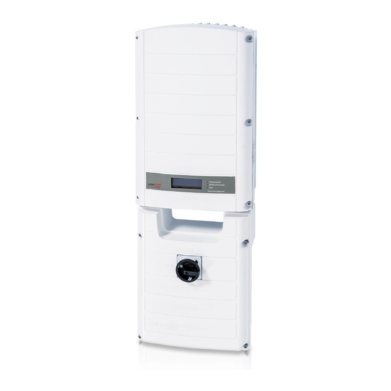
Chapter 3: Installing the Inverter Chapter 3: Installing the Inverter Install the inverter either before or after the modules and power optimizers have been installed. Inverter Package Contents One StorEdge inverter One mounting bracket Two Allen screws for fastening the inverter to the mounting bracket Installation guide (with activation card and instructions) Identifying the Inverter Refer to the sticker on the inverter t hat specifies its Serial Number and its Electrical Ratings. P rovide the serial number when contacting SolarEdge support. The serial number is also required when opening a new site in the SolarEdge monitoring portal. SolarEdge-StorEdge Installation Guide MAN-01-00262-1.0... -
Page 19: Inverter Interfaces
Monitoring information is being received from a power optimizer. inverter shutdown The inverter is being shut down. On - There is an error. Refer to "Troubleshooting" on page 79 for more Fault information. Blinking - The inverter is being shut down. SolarEdge-StorEdge Installation Guide MAN-01-00262-1.0... -
Page 20: Storedge Connection Unit Interfaces
Chapter 3: Installing the Inverter All LEDs turn on while the inverter is being configured. Figure 8: Inverter front view AC and DC conduit entries: Connection points of the StorEdge Connection Unit. ON/OFF switch: Turning this switch ON starts the operation of the power optimizers, enables power production and allows the inverter to begin exporting power to the utility grid/backed-up loads. Turning it OFF reduces the power optimizer voltage to a low safety voltage and inhibits exportation of power. When this switch is OFF, the inverter control circuitry remains powered up. LCD light button: Pressing this button lights up the LCD for 30 seconds. In addition, you can press this button to access configuration menu options, as described Configuring the Inverter Using the LCD Light Button on page 43. Two communication glands, for connection of inverter communication options. Each gland has three openings. Refer to Setting Up Communication to the Monitoring Portal on page 71 for more information. StorEdge Connection Unit Interfaces The following components are part of the StorEdge Connection Unit and may be accessed for ... -
Page 21: Opening Conduit Knockouts
To open conduit knockouts: 1. Move the StorEdge Connection Unit s afety switch and the inverter ON/OFF switch to OFF. NOTE When the StorEdge Connection Unit safety switch is OFF (for example during maintenance) it may be locked to prevent safety hazard: 1. Move the StorEdge Connection Unit safety switch to the Lock position. - Page 22 Chapter 3: Installing the Inverter 2. Loosen the screws on the front cover of the StorEdge Connection Unit using the supplied Allen key, as shown below: Figure 10: Opening the StorEdge Connection Unit cover 3. Remove the StorEdge Connection Unit cover. 4. Open the required conduit knockouts according to the conduits used in the installation (refer to the figure below for required knockouts; some of the knockouts may already be open but sealed): The knockouts are located at the bottomof the enclosure, each with two sizes: ¾'' and 1''. Open the required knockouts, taking care not to interfere with any of the internal components. A Unibit drill may be used. Figure 11: StorEdge Connection Unit knockouts NOTE Unused conduit openings and glands should be sealed with appropriate seals.
-
Page 23: Mounting The Inverter
Recommended: a stainless steel 3/4" long screw, with a 1/4" socket button head , two jam nuts and three washers. 4. Hang the inverter on the bracket (see F igure 12): Lift the inverter from the sides, or hold it at the top and bottom of the inverter to lift the unit into place. Do not lift holding the Safety SwitchStorEdge Connection Unit as it may be damaged. SolarEdge-StorEdge Installation Guide MAN-01-00262-1.0... - Page 24 Chapter 3: Installing the Inverter Align the two indentations in the inverter enclosure with the two triangular mounting tabs of the bracket, and lower the inverter until it rests on the bracket evenly. Figure 12: Hanging the inverter on the bracket 5. Secure the StorEdge Connection Unit bracket to the wall: Mark the location of the bracket screw for the Safety SwitchStorEdge Connection Unit and drill the hole. Fasten the bracket using a standard bolt. Verify that the bracket is firmly attached to the mounting surface. Figure 13: StorEdge Connection Unit bracket 6. Insert the two supplied screws through the outer heat sink fin on both sides of the inverter and into the bracket (see Figure 12). Tighten the screws with a torque of 4.0 N*m / 2.9 lb.*ft. 7. Remove the inverter cover: Open the inverter cover’s six Allen screws and carefully pull the cover horizontally before lowering it. SolarEdge-StorEdge Installation Guide MAN-01-00262-1.0...
-
Page 25: Chapter 4: Auto-Transformer And Backed-Up Loads Panel Installation (For Backup Only)
Chapter 4: Auto-transformer and Backed-up Loads Panel Installation (for Backup Only) Chapter 4: Auto-transformer and Backed-up Loads Panel Installation (for Backup Only) The auto-transformer is used for backup power only, and is not mandatory if using Smart Energy Management applications only. The auto-transformer connects to the AC side of the inverter. Since the inverter AC connections are on its right side, it is recommended to position the auto-transformer to the right of the inverter to simplify wiring. SolarEdge-StorEdge Installation Guide MAN-01-00262-1.0... -
Page 26: Mounting The Auto-Transformer
8 in / 200 mm to the top and bottom of the auto-transformer; if conduit entry to the auto- transformer will be from the bottom, leave sufficient clearance for the conduits as well. 4 in / 100 mm to the right and left of the auto-transformer. 2. Install the bracket with the flat side facing down. Verify that the bracket is firmly attached to the mounting surface. 3. Hang the auto-transformer on the bracket: Lift the a uto-transformer from the sides, or hold it at the top and bottom to lift the unit into place. 4. Insert the two supplied screws through the outer heat sink fin on both sides of the auto-transformer and into the bracket. Tighten the screws with a torque of 4.0 N*m / 2.9 lb.*ft. Figure 14: Installing the auto-transformer Installing the Backed-up Loads Panel Install a secondary AC panel for backed-up loads (not supplied by SolarEdge). Rewire the backed-up loads through this panel. Install two poles 25A main circuit breaker with integrated AFCI o n this panel, to ensure the 25A phase imbalance limit is maintained at all times. Figure 15: Backed-up Loads Panel SolarEdge-StorEdge Installation Guide MAN-01-00262-1.0... -
Page 27: Chapter 5: Electricity Meter Installation
The meter is connected to the inverter using RS485. NOTE The inverter RS485 bus should be connected to the battery and meter. Connecting multiple inverters with RS485 master-slave connection requires an RS485 Expansion Kit (available form SolarEdge Refer to http://www.solaredge.com/files/pdfs/RS485_expansion_kit_installation_guide.pdf). To install the SolarEdge meter refer to the installation guide supplied with it: ... -
Page 28: Chapter 6: Storedge Inverter Connections
Chapter 6: StorEdge Inverter Connections Chapter 6: StorEdge Inverter Connections After installing the system components, connect them to the StorEdge Connection Unit as described in this chapter. NOTE The conduits, hubs and fittings must be suited for field wiring systems. The hubs and other fittings must comply with UL514B. Use the conduit and wiring appropriate for the installation location per the NEC. -
Page 29: Installing The 9V Battery
Installing the 9V Battery The following figure summarizes the connections in the StorEdge Connection Unit: Figure 16: The StorEdge Connection Unit connections Installing the 9V Battery The 9V battery is supplied with the inverter accessories. 1. Open the four internal screws securing the transparent cover to the StorEdge Connection Unit enclosure and remove the cover. 2. Install the 9V battery in the holder on the top board of the StorEdge Connection Unit and connect it to the battery pad. Figure 17: The battery holder SolarEdge-StorEdge Installation Guide MAN-01-00262-1.0... -
Page 30: Connecting To Dc
For systems with three PV strings or more, fuses may need to be installed in both the positive and negative conductors as required by Article 690.35(B). For more information, refer to the Technical Note “String Fusing Requirements in SolarEdge Systems” at http://www.solaredge.com/files/pdfs/string_fusing_requirements.pdf. -
Page 31: Connecting To The Battery
THERMAL - 2-wire shielded twisted pair cable Push the lever to open the connection, (black) 16AWG (12-28AWG), 600V insert the wire and release the lever Battery insulated when the wire is clamped. Thermal V+ THERMAL + (red) SolarEdge-StorEdge Installation Guide MAN-01-00262-1.0... - Page 32 Chapter 6: StorEdge Inverter Connections StorEdge Recommended cable type Connection Tesla battery Connection method (min-max AWG) Unit connection connection Control and monitoring 5-pin communication port communication 1 (located closer to terminal block: the DIP switches): 5-wire shielded twisted pair cable...
- Page 33 Connecting to the Battery Figure 19: Connections to Tesla PowerWall Battery SolarEdge-StorEdge Installation Guide MAN-01-00002-4.0...
- Page 34 Connecting to the Battery Figure 20: Battery DIP switches SolarEdge-StorEdge Installation Guide MAN-01-00002-4.0...
-
Page 35: Connecting To Ac
Line terminal: L2 Insert the wire into the round opening and release the screwdriver to spring back and 3-pin terminal block: N Neutral terminal: N clamp the wire. Grounding 10 AWG cable Grounding Bus-bar Grounding lug SolarEdge-StorEdge Installation Guide MAN-01-00262-1.0... - Page 36 Chapter 6: StorEdge Inverter Connections Recommended StorEdge Con- Auto-transformer cable type (min- nection Unit Connection method connection max AWG) connection Temperature Sensor StorEdge Connection Unit: Press the protrusion at the top of the terminal block to open the External Devices 7-pin...
-
Page 37: Connecting To The Grid And To Backed-Up Loads
3-pin terminal block: L1 Backed-up loads panel: L1 6 AWG (4-20 AWG) 3-pin terminal block: L2 Backed-up loads panel: L2 3-pin terminal block: N Backed-up loads panel: N Min. 10 AWG grounding wire to ground SolarEdge-StorEdge Installation Guide MAN-01-00262-1.0... -
Page 38: Connecting Communication To The Meter
Ext. Devices 7-pin terminal shielded twisted pair, 600V RS485 4-pin terminal block: B, A, G block: B, A, G insulated If you have a meter with SolarEdge label, connect as illustrated below: Figure 23: Connection to a meter (SolarEdge If you have a meter with WattNode label, connect as illustrated below: Figure 24: Connection to a meter (WattNode) SolarEdge-StorEdge Installation Guide MAN-01-00262-1.0... -
Page 39: Dip Switch Setup According To System Application
Auto-transformer with connected over-temperature sensor Up (ON) - default Down (OFF) - default No auto-transformer, or auto-transformer with over- Up (ON) - default Up (ON) temperature sensor not connected Figure 25: StorEdge Connection Unit DIP switches SolarEdge-StorEdge Installation Guide MAN-01-00262-1.0... -
Page 40: Chapter 7: User Interface
Up (1) and Down (2): Moves the cursor from one menu option to another, moves among the characters of a displayed parameter, and toggles between possible characters when setting a value. (3): Selects a menu option and accepts a value change with a long press (until Applied is displayed). Use the three rightmost buttons for entering 123 when entering the Setup mode password 12312312. The LCD screen displays status information of the system and various menus for configuration options. The LCD panel and buttons are used during the following processes: Operational mode: The LCD panel allows checking for proper system o peration. Refer to Status Screens - Operational Mode on page 49 for a description of this option. Use the LCD light button to toggle through the informative displays. Setup mode: Upon installation, the installer may perform basic configuration Error messages: In the event of a problem, an error message may be displayed on the LCD panel. Removing the Inverter Cover Use the following procedure for cover removal for communication connection or maintenance. 1. Turn OFF, or verify that the StorEdge Connection Unit is OFF. 2. Turn OFF, or verify that the inverter ON/OFF switch is OFF. 3. Verify that AC to the inverter is OFF, or disconnect the AC to the inverter by turning OFF the circuit SolarEdge-StorEdge Installation Guide MAN-01-00262-1.0... -
Page 41: Inverter Configuration - Setup Mode
4. Open the inverter cover’s six Allen screws and carefully pull the cover horizontally before lowering it. CAUTION! When removing the cover, make sure not to damage internal components. SolarEdge will not be held responsible for any components damaged as a result of incautious cover removal. Lors du retrait du couvercle, assurez-vous de ne pas endommager les composants internes. - Page 42 C o n f < M T R > 1 If ZigBee is connected, the Wi-Fi Conf menu is not displayed. If ZigBee is not connected, ZigBee Conf and Wi-Fi Conf are both displayed with <N/A>. SolarEdge-StorEdge Installation Guide MAN-01-00262-1.0...
- Page 43 V e r s i o n s E r r o r L o g W a r n i n g l o g H a r d w a r e I D s SolarEdge-StorEdge Installation Guide MAN-01-00262-1.0...
-
Page 44: Configuring The Inverter Using The Lcd Light Button
E n g l i s h G e r m a n S p a n i s h F r e n c h I t a l i a n E x i t SolarEdge-StorEdge Installation Guide MAN-01-00262-1.0... - Page 45 C o n f . G r i d P r o t e c t i o n E x i t The options presented in these menus are described in the next section. 1 If Wi-Fi is connected, the ZigBee Conf menu is not displayed, and vice versa. SolarEdge-StorEdge Installation Guide MAN-01-00262-1.0...
-
Page 46: Configuration Menu Options
The communication option used by t he inverter to communicate with the SolarEdge monitoring portal The communication option used to communicate between multiple S olarEdge devices or other external non-SolarEdge devices, such as electricity meters or loggers. 2. Select Server to set which communication method is used to communicate between d evices and the SolarEdge monitoring portal. Refer to f or a full description of these communication options. NOTE The Server menu shows only the communication options installed in the inverter. The following shows a hierarchical tree of the menu options in the Communication menu. For detailed information about all the configuration options, refer to the Communication Options Application Note, available on the SolarEdge website at http://www.solaredge.us/files/pdfs/solaredge- communication_options_application_note_v2_250_and_above.pdf. SolarEdge-StorEdge Installation Guide MAN-01-00262-1.0... - Page 47 P r o f i l e < Z B 2 0 0 7 > 1 If ZigBee is connected, the Wi-Fi Conf menu is not displayed. If ZigBee is not connected, ZigBee Conf and Wi-Fi Conf are both displayed with <N/A> and their menus are not accessible. SolarEdge-StorEdge Installation Guide MAN-01-00262-1.0...
-
Page 48: Power Control
L o a d D e f a u l t s NOTE Phase Balance is applicable to single phase inverters only. For detailed information, refer to the SolarEdge Phase Balancing Manual, available on the SolarEdge website at http://www.solaredge.us/files/pdfs/phase_balancing_connection_guide.pdf The Grid Control option is disabled by default. Enabling it opens additional options in the menu, as shown on page 41. -
Page 49: Maintenance
H a r d w a r e I D s Versions: Displays inverter firmware versions: ID: The inverter ID. DSP 1/2: The DSP digital control board firmware version CPU: The communication board firmware version NOTE Please have these numbers ready when you contact SolarEdge Support. Error Log: Displays the last five errors. Warning Log: Displays the last five warnings. SolarEdge-StorEdge Installation Guide MAN-01-00262-1.0... -
Page 50: Status Screens - Operational Mode
T e m p 5 0 . 0 W W W W W W 2 8 . 2 Vac [V: The AC output voltage. Vdc [V]: The DC input voltage. Pac [W]: The AC output power. Fac [Hz]: The AC output frequency. OPs_Ok: Number of optimizers sending telemetries (indicating that they are paired) Temp [C or F]: The inverter heat sink temperature SolarEdge-StorEdge Installation Guide MAN-01-00262-1.0... -
Page 51: Energy Meter Status
E n e r g y [ W h ] : 0 V d c _ O [ V ] : 0 . 5 V d c _ I [ V ] : 2 9 . 5 Module#: Power optimizer serial number Energy: power optimizer energy Vdc_O: Power optimizer output voltage Vdc_I: Power optimizer input voltage (module voltage) SolarEdge-StorEdge Installation Guide MAN-01-00262-1.0... -
Page 52: Id Status
This screen describes the ZigBee configuration: P A N : X X X X X C H : X X / X X X X R S S I : < L > M I D : X X X X SolarEdge-StorEdge Installation Guide MAN-01-00262-1.0... -
Page 53: Cellular Status
R S 4 8 5 - 1 < S E > < S > < - - > Z i g B e e < S E > < M P S > < - - > SolarEdge-StorEdge Installation Guide MAN-01-00262-1.0... -
Page 54: Smart Energy Management Status
1 0 . 0 4 C o s P h i : 0 . 9 P o w e r P r o d : 7 0 0 0 W PWR CTRL: The power control status: REMOTE - Communication with the RRCR or smart energy manager is confirmed/validated. LOCAL - The power is controlled locally (e.g. by a fixed limit), or this inverter limits the PV power production to its relative portion of the feed-in power limit, as a result of disconnected communication with the smart energy manager. If this status appears, check the communication to the smart energy manager or the communication to the meter. SolarEdge-StorEdge Installation Guide MAN-01-00262-1.0... -
Page 55: Battery Status
< R e m o t e > S e t U n t i l : < d a t e > Name: The TOU profile file name Last Sync: Date when the time-of-use profile was loaded from the monitoring portal Source: the source from which the TOU profile was uploade: Remote - Profile uploaded from the SolarEdge monitoring portal Local - Profile uploaded from an SD card Set Until: The date until the current profileis applicable SolarEdge-StorEdge Installation Guide MAN-01-00262-1.0... -
Page 56: Chapter 8: Commissioning The Installation
Step 1: Activating the System 1. Verify that the inverter ON/OFF switch is OFF. 2. Move the StorEdge Connection Unit ON/OFF switch to the ON position. WARNING! ELECTRICAL SHOCK HAZARD. Do not touch uninsulated wires when the inverter cover is removed. RISQUE D’ÉLECTROCUTION, ne touchez pas les fils non isolés lorsque le couvercle de l'onduleur est retiré. SolarEdge-StorEdge Installation Guide MAN-01-00262-1.0... - Page 57 C o u n t r y : U S A 1 5. If required, perform the following additional steps before closing the inverter cover: Country settings or inverter configuration using the internal LCD user buttons – refer to Country and Grid on page 45. Communication options connection – refer to Setting Up Communication to the Monitoring Portal on page 71. StorEdge application configuration - refer to System Configuration on page 62. 6. Close the inverter cover b y tightening the screws with a torque of 9.0 N*m/ 6.6 lb*ft. For proper sealing, first tighten the corner screws and then the two central screws. The following figure illustrates recommended order: Figure 28: Tightening order of the screws 7. Make sure the AC Bypass switch is switched to the left (position 1). SolarEdge-StorEdge Installation Guide MAN-01-00262-1.0...
- Page 58 Chapter 8: Commissioning the Installation 8. Make sure the backed-up loads AC breaker is UP. Figure 29: StorEdge Connection Unit 9. Close the StorEdge Connection Unit cover: Attach the cover and secure it by tightening the six screws with a torque of 1.2 N*m / 0.9 ft.*lb. 10. Ensure proper conduit sealing; inspect the entire conduit run and use standard conduit sealants to avoid water penetration. 11. Turn ON the S torEdge Connection Unit switch. I f an additional external DC switch is installed between the power optimizers/ battery and the inverter(s) then turn it ON. A status screen similar to the following appears on the LCD panel: V a c [ V ] V d c [ V ] P a c [ w ] 2 4 0 .
-
Page 59: Step 2: Pairing Power Optimizers To The Inverter
T u r n S w i t c h 2. Turn the inverter ON/OFF switch to ON within 5 seconds. If you wait longer than 5 seconds the inverter exits the pairing mode. The following message is displayed indicating that the inverter is performing the pairing: P a i r i n g R e m a i n i n g [ s e c ] : 1 8 0 SolarEdge-StorEdge Installation Guide MAN-01-00262-1.0... - Page 60 S e c The countdown indicates the seconds remaining until entering the Production mode. This time is in accordance with local regulations and is typically between three to five minutes. When countdown is complete, the inverter enters Production mode and produces power. The steadily lit green inverter LED indicates this mode. 4. Scroll to the M aintenance menu and select Optimizer Conf. è Set Rapid ShutdownèEnable. S e t R a p i d S h u t d o w n E x i t SolarEdge-StorEdge Installation Guide MAN-01-00262-1.0...
-
Page 61: Step 3: Verifying Proper Operation
This step requires connecting one of the communication options. Refer to Setting Up Communication to the Monitoring Portal on page 71. The SolarEdge Monitoring System The SolarEdge monitoring portal enables accessing SolarEdge site information, including up-to-date information viewed in a physical or logical view.The monitoring portal is described in detail in the SolarEdge Monitoring Portal User Guide, available on the SolarEdge website at http://www.solaredge.us/files/pdfs/solaredge-monitoring-portal-user-guide.pdf. The SolarEdge monitoring portal can display logical and physical layouts of the installed system, as follows: Logical Layout: Shows a schematic logical layout of the components in the system, such as: inverters, strings and modules, as well as their electrical connectivity. This view enables you to see which modules are connected in each string, which strings are connected to each inverter, and so on. Physical Layout: Shows a schematic physical layout of the components in the system, such as: inverters, strings and modules, as well as their electrical connectivity. This view enables a bird’s eye view of the actual location of a system component. SolarEdge-StorEdge Installation Guide MAN-01-00262-1.0... -
Page 62: Providing Installation Information
If you do not report the physical and logical mapping of the installed power optimizers to SolarEdge, the SolarEdge monitoring portal will show the logical layout indicating which power optimizers are connected to which inverter, but will not show strings or the physical location of power optimizers. The inverter may be connected to the SolarEdge monitoring portal via LAN or via an external modem connected to the inverter's RS232 connector. Alternatively, you can connect the inverter to another inverter that is already connected to the server, in a master-slave configuration. Refer to Setting Up Communication to the Monitoring Portal on page 71 . Providing Installation Information Paper Template Fill out the Physical Layout Template (downloadable from the SolarEdge site) using the detachable 2D barcode stickers on each power optimizer. Once the form is completed, scan it and upload the scanned file to the SolarEdge monitoring portal during site registration. For an example paper template, refer to http://www.solaredge.us/files/pdfs/physical-layout-template.pdf. Site Mapper Use the SolarEdge Site Mapper smartphone application to scan the power optimizer and inverter 2D barcodes. The application creates an XML file that can be uploaded to the SolarEdge monitoring portal during site registration. The SolarEdge Site Mapper can be downloaded from the application stores. For detailed information, refer to the SolarEdge Site Mapper Software Guide or to the Site Mapper demo movie, available on the SolarEdge website at http://www.solaredge.us/groups/installer-tools/site- mapper. Creating a Site in the SolarEdge Monitoring Portal Create the site in the monitoring portal using the registration form available at http://www.solaredge.us/groups/site-registration . Fill out all required information in the form, which includes information about your installation, as well as details about its logical and physical mapping. SolarEdge-StorEdge Installation Guide MAN-01-00262-1.0... -
Page 63: Chapter 9: System Configuration
Chapter 9: System Configuration This chapter describes how to configure your StorEdge system by setting up the communication between the system components and setting up the required a pplication. Configuring the RS485 Bus for Battery and Meter Connection This section describes how to set up the RS485 communication between the i nverter, meter and battery. Some inverters are equipped with a built-in Revenue Grade Meter (RGM), which is located in the StorEdge Connection Unit. When an additional meter is installed for these inverters, the second meter is connected to the existing RGM in a daisy chain. To configure the RS485 bus: 1. Turn OFF or verify that the StorEdge Connection Unit switch i s OFF. 2. Turn the inverter ON/OFF switch to OFF. SolarEdge-StorEdge Installation Guide MAN-01-00262-1.0... - Page 64 P r o t o c o l < T 7 4 > D e v i c e < 2 4 > B a t t e r y I n f o < > 7. Select Device Type è Battery Pack. SolarEdge-StorEdge Installation Guide MAN-01-00262-1.0...
- Page 65 S O E : 8 9 % W W W W W P W R : T o t a l : 0 W h S t a t e : I d l e If Comm. Error appears, refer to Troubleshooting on page 79. SolarEdge-StorEdge Installation Guide MAN-01-00262-1.0...
-
Page 66: Configuring Storedge Application
< D i s > W a k e u p C o n f . P ( f ) A d v a n c e d L o a d D e f a u l t s SolarEdge-StorEdge Installation Guide MAN-01-00262-1.0... - Page 67 E n e r g y C t r l < M S C > S e t O p e r a t i o n S t o r a g e C o n t r o l SolarEdge-StorEdge Installation Guide MAN-01-00262-1.0...
- Page 68 < E n > D i s p l a y M a i n t e n a n c e I n f o r m a t i o n b. From the main menu select Backup Conf. SolarEdge-StorEdge Installation Guide MAN-01-00262-1.0...
-
Page 69: Verifying Storedge Components Functionality
Verifying StorEdge Components Functionality 2. To set a minimum battery charge level, so that the battery will always have energy stored in case backup power is needed, do the following: a. From the Energy Manager menu select S torage Control. The following is displayed: B a c k u p R S V D < % P V > b. Select Backup RSVD and set the required level as precentage of the battery capacity: For backup power + Smart Energy Management - according to user requirement For backup-only - according to battery manufacturer recommendation, if provided Verifying StorEdge Components Functionality Upon installation and configuration completion, the system should be operating according to the ... - Page 70 3 7 1 . 9 2 3 4 9 . 3 P _ O K : X X X / Y Y Y < S _ O K > B a c k u p M o d e SolarEdge-StorEdge Installation Guide MAN-01-00262-1.0...
- Page 71 Verifying StorEdge Components Functionality 2. Press the external LCD light button to display the battery status screen, and check that: The battery State is: Discharging / Charging The SOE percentage is decreasing/increasing The PWR value is greater than 0 B S N : X X X X X X X X X I D : 2 4 S O E : 8 9 % W W W W W...
-
Page 72: Chapter 10: Setting Up Communication To The Monitoring Portal
MARCHE/ARRÊT à la base de l'onduleur soit en position ARRÊT, et le CA est en position ARRÊT. Lors de la configuration des paramètres de communication, assurez-vous que l'interrupteur MARCHE/ARRÊT soit en position ARRÊT, et le CA est en position MARCHE. SolarEdge-StorEdge Installation Guide MAN-01-00262-1.0... -
Page 73: Communication Types
External antenna cable 2-4 mm 1 (PG16) Ethernet connection (CAT5/6), ZigBee, Two large 4.5-7 mm Cellular 2 (PG13.5) All three RS485, power reduction 2.5-5 mm Figure 30: Communication Glands The communication board has a standard RJ45 terminal block for Ethernet connection, and a 9-pin terminal block for RS485 connection, a s shown below: Figure 31: Internal connectors SolarEdge-StorEdge Installation Guide MAN-01-00262-1.0... -
Page 74: Creating An Ethernet (Lan) Connection
The gland includes a rubber waterproof fitting, which should be used to ensure proper sealing. Le cote interne du gland contient une rondelle qui doit être utilisée pour une bonne étancheïté. 3. Remove the plastic seal from the large opening that has a cut in the rubber fitting . 4. Remove the rubber fitting from the gland and insert the CAT5/6 cable through the gland and through the gland opening in the inverter . 5. Push the cable into the cut opening of the rubber fitting. Figure 33: Rubber fitting SolarEdge-StorEdge Installation Guide MAN-01-00262-1.0... - Page 75 a. Insert the cable through gland #1. b. Remove the cable’s external insulation using a crimping tool or cable cutter and expose eight wires. c. Insert the eight wires into an RJ45 connector, as described in Figure 34 d. Use a crimping tool to crimp the connector. e. Connect the Ethernet connector to the RJ45 port on the communication board. Figure 35: The RJ45 Ethernet connection 1 The inverter connection does not support RX/TX polarity change. Supporting crossover Ethernet cables depends on the switch capabilities. SolarEdge-StorEdge Installation Guide MAN-01-00262-1.0...
-
Page 76: Creating An Rs485 Bus Connection
NOTE If a revenue grade meter is connected to your inverter, it uses the RS485 port and therefore an RS485 communication bus cannot be created. The following sections describe how to physically connect the RS485 bus and how to configure the bus. SolarEdge-StorEdge Installation Guide MAN-01-00262-1.0... - Page 77 Creating an RS485 Bus Connection To connect the RS485 communication bus: 1. Remove the inverter cover as described in Removing the Inverter Cover on page 39. 2. Remove the seal from one of the openings in communication gland and insert the wire through the opening. 3. Pull out the 9-pin RS485 terminal block connector, as shown below: Figure 36: The RS485 terminal block 4. Loosen the screws of pins A(+), B(-), and G on the left of the RS485 terminal block. Figure 37: RS485 terminal block 5. Insert the wire ends into the G, A and B pins shown above. Use Four- or six-wire twisted pair cable for this connection. You can use any color wire for each of the A, B and G connections, as long as the same color wire is used for all A pins, the same color for all B pins and the same color for all G pins. SolarEdge-StorEdge Installation Guide MAN-01-00262-1.0...
- Page 78 10. Terminate the first and last SolarEdge device (inverter/Control and communication gateway, etc.) in the chain by switching a termination DIP-switch inside the inverter to ON (move the switch up). The switch is located on the communication board and is marked SW7. Figure 39: RS485 termination switch NOTE Only the first and last SolarEdge devices in the chain should be terminated. The other inverters in the chain should have the termination switch OFF (down position). SolarEdge-StorEdge Installation Guide MAN-01-00262-1.0...
-
Page 79: Verifying The Connection
P _ O K : 0 0 0 / 0 0 0 < S _ O K > - - - - - - - - - - - - - - - O F F S_OK: Indicates that the connection to the SolarEdge monitoring portal is successful. If S_OK is not displayed, refer to "Troubleshooting" on the facing page. SolarEdge-StorEdge Installation Guide MAN-01-00262-1.0... -
Page 80: Appendix A: Troubleshooting
S t a t u s : < O K > x x x x x x x x < E R R O R M E S S A G E > xxxxxxxx is a string of 1s and 0s showing an eight-bit communication connection status. 1 indicates OK and 0 indicates an error. SolarEdge-StorEdge Installation Guide MAN-01-00262-1.0... -
Page 81: Meter Troubleshooting
If G Server Ping Failed internet access is unavailable, contact your IT admin or your internet provider. Ping or connection to SolarEdge server failed.. Check the SolarEdge server address, under LAN Conf submenu: Server x Ping Failed Address: prod.solaredge.com... -
Page 82: An Error Message Is Displayed
The AC connection of the meter Total [Wh] Import value is not advancing If the inverter is not producing power, and there is power consumption by the loads, the Total [Wh] value should be changing. If the Total [Wh] value of the Import meter displays a steady value although the site is consuming power, check the following: The meter status LEDs are lit. If the LEDs are all OFF, the meter is not connected to a power source. Check the meter AC connection (10-pin terminal block) Check that the meter breaker is ON There are no loose connections at the 10-pin AC wiring of the meter. The CT black and white cables are correctly connected to the 6-pin connector on the meter: White CT wire is connected to L1 white Black CT wire is connected to L1 black CT direction is towards the grid and the green power LEDs are ON. If the LEDs are not green indicating import power - the CTs are reversed. Figure 40: Meter with CT SolarEdge-StorEdge Installation Guide MAN-01-00262-1.0... -
Page 83: Battery Troubleshooting
Check that the AC circuit breaker in During normal operation (grid Internal circuit breaker has been the StorEdge Connection Unit is in the supplies power), no power to the triggered UP position (see Figure 9) -
Page 84: Error Codes
StorEdge Connection Unit are in the UP position (see Figure 9) Check that the AC bypass switch in the StorEdge Connection Unit is set to position 1 (see Figure 9) . Inverter without auto-transformer Move the DIP switch SW2 in the... -
Page 85: General Inverter Error Codes
Check with the grid operator if a large surge source or 9, 13 Surge irregular load exists near the site. If the grid does not have problems contact SolarEdge support. Ground faults may occur due to insufficient insulation to the ground. - Page 86 Refer to the AC Wiring Application Note http://www.solaredge.us/files/pdfs/application-note- recommended-wiring.pdf The SolarEdge system normally eliminates DC overvoltage errors. If the fault persists: Turn OFF the inverter ON/OFF switch. If after five minutes, the LCD panel does not show a low safety...
- Page 87 Turn the inverter OFF and ON. If the fault persists, contact 99-101 High Line 1/2/3 SolarEdge support. Temperature Make sure the inverter is installed in a location with ambient Too Low temperatures within the range specified in the datasheet. Ground Current Contact SolarEdge support. SolarEdge-StorEdge Installation Guide MAN-01-00262-1.0...
-
Page 88: Storedge-Related Errors Codes
Check the communication cable between the StorEdge Connection Unit and the digital board in the inverter. Communication Error Check that the StorEdge Connection Unit LEDs are ON. Inverter production stopped due to StorEdge Connection Unit overheating or due to internal fan malfunction. -
Page 89: Storedge Connection Unit Leds
There are three LEDs on the lower board of the StorEdge Connection Unit, near the DIP switches: Figure 41: StorEdge Connection Unit LEDs In normal operation, t he middle and bottom LEDs indicate auxiliary voltages (13V from DC/DC, 5V and 3.3V) and should always be lit. The top LED should be lit when the inverter DC voltage is at least 200 Vdc (check when both inverter ON/OFF switch and StorEdge Connection Unit switch are ON). You can check the status screen for the Vdc value. If all LEDs are OFF: Check that AC voltage exists in the inverter ... - Page 90 Problem Possible cause and troubleshooting Power optimizers are shaded. If you connected the inverter to the SolarEdge monitoring portal, retry pairing Pairing failed remotely (during sunlight).Make sure to leave the inverter ON/OFF switch ON and that S_OK appears on the LCD..
-
Page 91: Appendix B: Replacing And Adding System Components
If you remove the old inverter and do not immediately install a new one, then: Lock the StorEdge Connection Unit in the OFF position using a lock on the switch. Use insulation tape to isolate each of the AC and DC wires. -
Page 92: 9V Battery Replacement
Si vous ne pouvez pas voir l'écran de l'onduleur ou si un dysfonctionnement est indiqué sur l'écran LCD, attendez cinq minutes pour que les condensateurs d'entrée de l'onduleur soient déchargés. 2. Turn OFF the StorEdge Connection Unit and the AC switch of the distribution panel. 3. Open and remove the StorEdge Connection Unit cover. 4. Open and remove the transparent internal cover. 5. Remove the battery from the upper board of the StorEdge Connection Unit and replace with a new standard 9V battery. 6. Close the StorEdge Connection Unit covers. Figure 42: The battery holder SolarEdge-StorEdge Installation Guide MAN-01-00262-1.0... -
Page 93: Fuse Replacement
4. Open and remove the internal transparent cover. 5. Remove the faulty fuse from the upper board of the StorEdge Connection Unit and replace with a new fuse. 6. Close the StorEdge Connection Unit covers. StorEdge Connection Unit Replacement Removing the Existing StorEdge Connection Unit 1. Turn OFF the inverter ON/OFF switch, and wait until the LCD indicates that the DC voltage is safe (<50V), or wait five minutes before continuing to the next step. WARNING! If you cannot see the inverter panel, or if a malfunction is indicated on the LCD panel, wait five minutes for the input capacitors of the inverter to discharge. -
Page 94: Installing A New Storedge Connection Unit
Appendix B: Replacing and Adding System Components 9. Unscrew the two conduit nuts securing the StorEdge Connection Unit to the external conduits. 10. Release the bracket securing the StorEdge Connection Unit to the wall. 11. Carefully remove the StorEdge Connection Unit with its mounting bracket from the wall. Installing a New StorEdge Connection Unit 1. Open the StorEdge Connection Unit cover. 2. Position the new StorEdge Connection Unit below the inverter and from the inside of the inverter grab the AC and DC wires extending from the unit conduits, as shown below: Figure 43: Inserting the AC and DC conduits 3. Attach the StorEdge Connection Unit with its bracket to the wall and slightly close the screws. Do not over tighten. 4. For RGM inverters - Insert the meter RS485 cable through the DC side conduit of the StorEdge Connection Unit and connect to the inverter communication board. 5. Reconnect the cable from the inverter digital board to the StorEdge Connection Unit.