
Related Manuals for Vaisala MHT410


Summary of Contents for Vaisala MHT410
- Page 1 M211737EN-F User Guide Vaisala Moisture, Hydrogen and Temperature Transmitter for Transformer Oil MHT410...
- Page 2 Street address: Vanha Nurmijärventie 21, FI-01670 Vantaa, Finland Mailing address: P.O. Box 26, FI-00421 Helsinki, Finland Phone: +358 9 8949 1 Visit our Internet pages at www.vaisala.com. © Vaisala Oyj 2018 local rules and regulations No part of this manual may be...
-
Page 3: Table Of Contents
Re-installing the Transmitter in New Location..........33 Analog Output....................36 Analog Output Overrange Behavior............36 Modbus......................38 Overview of Modbus Protocol Support............38 Vaisala Industrial Protocol................ 39 Connecting via Service Port................. 40 7.1.1 Installing the Driver for the USB Service Cable........40 7.1.2 Connecting USB Cable................ - Page 4 MHT410 User Guide M211737EN-F Serial Commands Summary................43 Device Information and Status Commands..........45 Serial Line Output and Communication Commands........51 7.4.1 Measurement Output Commands............51 7.4.2 Measurement Output Format Commands........... 55 7.4.3 Serial Line Communication Commands..........58 Analog Output Commands................62 Calibration and Adjustment Commands.............
- Page 5 Table of Contents Appendix A: Operating Principle..............101 Method Used for Measuring Moisture in Oil..........102 Transformer Oil..................... 102 Appendix B: Modbus Reference..............104 Function Codes.....................104 Data Encoding....................104 B.2.1 32-Bit Floating Point or Integer Format..........104 B.2.2 16-Bit Integer Format................105 Register Map....................
- Page 6 Figure 6 MI70 Basic Display...................76 Figure 7 Example of MI70 Display with MHT410 in Port I and MM70 Probe in Port II. Shown Parameters: aw (I), aw (II), Δ aw..81 Figure 8 Wiring Option 1: Wiring with Four Power Supplies.
- Page 7 Reset Command....................69 Table 40 H2 is Command....................69 Table 41 Default Communication Settings..............70 Table 42 Service Port Serial Interface Settings............73 Table 43 Possible Error Messages via Vaisala Industrial Protocol......87 Table 44 Measurement Performance................90 Table 45 Operating Environment................... 91...
- Page 8 Compliance......................92 Table 49 Display with Relays (External Option)............93 Table 50 Spare Parts and Accessories................. 94 Table 51 Vaisala Cable CBL210392-5M Wire Colors (When Pre-Wired).... 96 Table 52 Materials for Recycling.................. 100 Table 53 Optimal Sensor Positions................101 Table 54 Modbus Function Codes................104 Table 55 16-bit Signed Integer Format Details............105...
-
Page 9: Safety
Chapter 1 – Safety 1. Safety Vaisala Moisture, Hydrogen and Temperature Transmitter MHT410 for Transformer Oil delivered to you has been tested for safety and approved as shipped from the factory. Note the following precautions: CAUTION! Read the Quick Guide (including installation instructions) carefully before installing the product. -
Page 10: Esd Protection
1.1 ESD Protection Electrostatic Discharge (ESD) can cause immediate or latent damage to electronic circuits. Vaisala products are adequately protected against ESD for their intended use. However, it is possible to damage the product by delivering an electrostatic discharge when touching, removing or inserting any objects inside the equipment housing. -
Page 11: About This Document
This document. Updated installation instructions regarding PTFE tape and installation depth. Added DNP3 protocol information. Added clarification about using the RS-485 line of the screw terminals with Modbus or Vaisala Industrial Protocol. Added maximum power consumption specification. Added new parameter options for analog... -
Page 12: Regulatory Compliances
Lists tools needed to perform the task. Indicates that you need to take some notes during the task. 2.2 Regulatory Compliances Up-to-date declarations of conformity are available at request from Vaisala (www.vaisala.com). This product is in compliance with the following EU directives: • EMC Directive •... -
Page 13: Product Overview
Chapter 3 – Product Overview 3. Product Overview Vaisala Moisture, Hydrogen and Temperature Transmitter MHT410 for Transformer Oil is designed for online monitoring of insulating oil in power transformers. The transmitter provides an accurate real-time measurement result of moisture, hydrogen and temperature measured in oil, enabling reliable conclusions on the transformer's condition without delay. -
Page 14: Product Parts And Package Contents
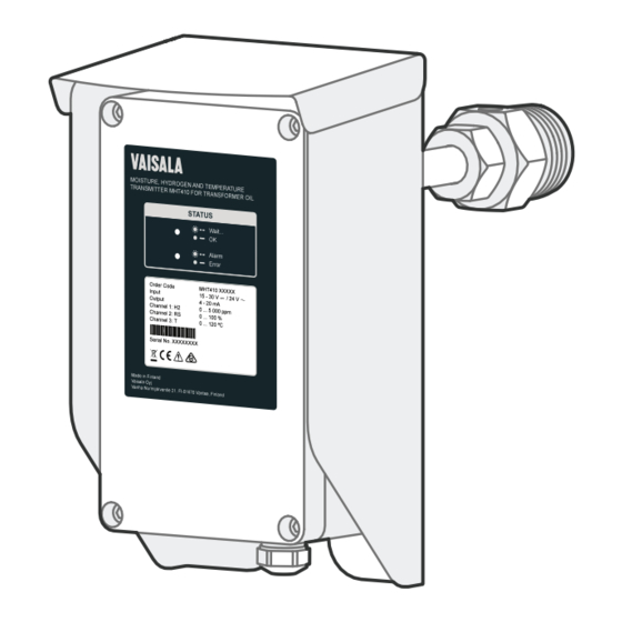
MHT410 User Guide M211737EN-F 3.2 Product Parts and Package Contents... - Page 15 Chapter 3 – Product Overview 5 mm 3 mm Item Electronics housing. The front cover is additionally connected to the housing with a grounding wire. Weather shield Bleed screw Probe body Small tightening nut, used to adjust and fix the depth of the transmitter in the valve. You can move the tightening nut and the mounting nut along the probe body.
-
Page 16: Measurement Parameters And Units
MHT410 User Guide M211737EN-F 3.3 Measurement Parameters and Units Parameter Abbreviation Unit concentration in oil • 1 h average • 24 h average Rate of change of H concentration In a day Daily ROC /day In a week Weekly ROC /week... -
Page 17: Data Logging
• Uptime and total operating time • Occasions of exceeding hydrogen alarm level (optional) To view the log and change the logging settings, use Vaisala Industrial Protocol. You can save the log as a file from PuTTY by configuring the following settings in PuTTY before opening the connection: In the Session >... - Page 18 MHT410 User Guide M211737EN-F LED Color and Text Description Red, blinking: concentration is above the alarm limit. Alarm Red, steady: Transmitter is in error state. Error...
-
Page 19: Installation
• Go through the check list in section Planning the Installation (page 17). • Read this whole guide carefully. The installation instructions in this section are the same as in the MHT410 Quick Guide. 4.1 Planning the Installation • Choose the installation location on the transformer (see... -
Page 20: Figure 1 Recommended Installation Locations
MHT410 User Guide M211737EN-F Figure 1 Recommended Installation Locations Recommendation Description This is the best location for the transmitter. The oil is measured in flow, which makes the oil sample representative and instant. This is essential especially for correct Recommended: oil moisture measurement. -
Page 21: Mechanical Installation
Chapter 4 – Installation Recommendation Description An instrumentation valve is recommended. This is a typical valve that is meant for oil analysis. Moisture response time is moderate depending on the oil volume Possible alternative: and transmitter installation. Wall of the oil tank, high enough from the bottom to enable proper oil movement. - Page 22 MHT410 User Guide M211737EN-F • 2 wrenches (50 mm and 36 mm) • Allen key (3 mm, provided) • PTFE tape (provided) • Gloves • Bucket and cloth 1. Remove the protective cap with sorbent packet from the mounting nut.
- Page 23 Chapter 4 – Installation 2. Apply PTFE tape tightly on the mounting nut threads. a. Before you start, clean the threads with a cloth. b. To make sure you wrap the tape in the correct direction, hold the transmitter so that the product label is facing you and the mounting nut points away from you.
- Page 24 MHT410 User Guide M211737EN-F 3. Make sure the bleed screw is closed. Fasten the mounting nut on the ball valve to finger- tightness with your hand. Leave the bleed screw directly on top of the nut. If you cannot position the bleed screw on top of the mounting nut by tightening just with your hand, you can use a wrench (50 mm) to turn the mounting nut a maximum of a ½...
- Page 25 Chapter 4 – Installation 5. Start opening the valve very carefully to let air out through the bleed screw. CAUTION! If you open the valve too quickly, the air inside the mounting nut will flow into the transformer instead. When oil flows out, close the bleed screw. Clean the area with a cloth and open the ball valve fully.
- Page 26 MHT410 User Guide M211737EN-F 7. Push the probe to the correct depth. The correct depth depends on where the installation valve is located: radiator pipe or transformer wall. • Valve in radiator pipe: Install the probe so that the back of the weather shield is 180 ...
- Page 27 Chapter 4 – Installation 8. Tighten the small tightening nut with a wrench until it the probe is securely fastened. 9. Press the caution sticker on the MHT410 weather shield or other visible location nearby. DO NOT CLOSE VALVE WHEN TRANSMITTER...
-
Page 28: Electrical Installation
MHT410 User Guide M211737EN-F More Information ‣ Dimensions (page 95) 4.3 Electrical Installation If the transmitter was ordered with the Vaisala cable CBL210392-5M, the cable is already pre-connected to the transmitter according to Wiring Option 1. - Page 29 • 2 medium wrenches (24 mm) • Flat head screwdriver (2.5 mm) • Wire-cutting pliers • Suitable cable. You can order the following cables from Vaisala: • 5 m shielded PUR cable (order code: CBL210392-5MSP) • 10 m shielded PUR cable (order code: CBL210392-10MSP)
- Page 30 MHT410 User Guide M211737EN-F 2. Hold the upper nut of the cable gland in place with a wrench (24 mm), and loosen the sealing nut of the gland with another wrench (24 mm). 3. Lead the cable through the sealing nut and the rubber seal. Turn the shield over the edge...
- Page 31 Chapter 4 – Installation 4. Lead the cable through the cable gland. Push the rubber seal back in place with the shield. Cut off any excess shield. Tighten the sealing nut with wrench (24 mm). 5. Pull the screw terminal blocks (2 pcs) off from the circuit board. 6.
-
Page 32: Loop-Powered Display
This display can be configured for other parameters (moisture/temperature in oil). If needed, you can install up to three displays, each showing a different parameter. The default display settings are presented in the Vaisala Technical Note inside the display package. If needed, configure the display functions and scaling according to the manufacturer's instructions delivered with the display. -
Page 33: Wiring The Loop-Powered Display
If one of the cable lead-throughs on your transmitter is plugged and you want to use that lead-through for the Nokeval display cable, you can order a cable gland from Vaisala. 1. Connect the loop-powered display to the transmitter as shown in the following wiring diagram. -
Page 34: Checklist After Installation
MHT410 User Guide M211737EN-F More Information ‣ Spare Parts and Accessories (page 94) ‣ Wiring Diagrams (page 96) 4.5 Checklist After Installation After the installation, check the following indicators to make sure the installation was successful: • No oil is leaking from the transformer and the transmitter. -
Page 35: Re-Installing The Transmitter In New Location
If you re-install the transmitter in a new location, you must initialize the transmitter after the re-installation by connecting to the service port and giving the initialization command using Vaisala Industrial Protocol. 1. Remove the transmitter. See Removing the Transmitter (page 32). - Page 36 MHT410 User Guide M211737EN-F 3. Connect to the transmitter via the service port and start communication using Vaisala Industrial Protocol. a. Connect to the service port (Connecting via Service Port (page 40)). b. If needed, install the USB driver (Installing the Driver for the USB Service Cable (page 40)).
- Page 37 Chapter 4 – Installation 8. Finish the initialization sequence by pressing the + key. 15832364.00 31.9565 30.84680 0.00 8086663 8086663 582 - - - - - htr_off wait <"+ key"> Quit hydrogen measurement module command line operation 9. Close the PuTTY terminal application. 10.
-
Page 38: Analog Output
If needed, you can allow the analog outputs to extend 10 % of the range over 20 mA using the aover command via Vaisala Industrial Protocol. With this extension, the allowed range for analog outputs is 4 ... 21.6 mA. The aover command does not affect the scaling of the outputs. -
Page 39: Figure 3 Analog Output Overrange Behavior
Chapter 5 – Analog Output CURRENT OUTPUT 21.6 mA 20 mA 4 mA MEASURED VALUE Low end High end High end of scale of scale of scale +10 % Analog output of scale Analog output extended at high end of range Figure 3 Analog Output Overrange Behavior More Information ‣... -
Page 40: Modbus
6. Modbus 6.1 Overview of Modbus Protocol Support MHT410 can be accessed using the Modbus serial communication protocol on the RS-485 line of the screw terminals. The supported Modbus variant is Modbus RTU (Serial Modbus). The supported Modbus functions and registers are described in... -
Page 41: Vaisala Industrial Protocol
Chapter 7 – Vaisala Industrial Protocol 7. Vaisala Industrial Protocol The transmitter provides an implementation of the Vaisala Industrial Protocol that can be used for service and configuration use, or for interfacing with the system to which the transmitter is integrated. The protocol is a plaintext protocol suitable for use both by human operators and automated systems. -
Page 42: Connecting Via Service Port
You can connect to the transmitter via Vaisala Industrial Protocol on a computer using the service port located under the transmitter cover. If you have not used the Vaisala USB cable before, install the driver before attempting to use the cable. -
Page 43: Connecting Usb Cable
3. Locate the cable in the list of devices: • If the device is listed as Vaisala USB Device with a COM port number in brackets, the cable is ready for use. Note the COM port number, you will need it later. -
Page 44: Table 5 Service Port Serial Interface Settings
3. Select Connection > Serial & USB and check that the correct COM port is selected in the Serial or USB line to connect to field. If you are using the PuTTY terminal application supplied by Vaisala, you can click the USB Finder button to open the Vaisala USB Instrument Finder program. -
Page 45: Serial Commands Summary
Show the software version information. Table 14 (page 50) Serial line output and communication: addr Show or set device address used in Modbus communication and Table 23 in Vaisala Industrial Protocol when the device is in POLL mode. (page 58) - Page 46 MHT410 User Guide M211737EN-F Command Description More information close Close connection to device in POLL mode. Table 24 (page 59) This command cannot be used via the Service Port. form Set output format of measurement messages. Table 19 (page 55) intv Set measurement output interval.
-
Page 47: Device Information And Status Commands
Chapter 7 – Vaisala Industrial Protocol Command Description More information ctext Show or set adjustment information text. Table 34 (page 66) h2 da Start or continue hydrogen calibration and adjustment sequence. Table 35 (page 67) h2 db Other commands: dnp3 addr... -
Page 48: Table 8 Alarm Command
MHT410 User Guide M211737EN-F Syntax Description Example: MHT410 / 0.1.20 Serial number : L2110001 Batch number : L1940010 Sensor number : L102 Sensor model : Humicap L2 Order code : MHT410 1CXEO Cal. date : 20150414 Cal. info : Vaisala... -
Page 49: Table 9 Errlog Command
Chapter 7 – Vaisala Industrial Protocol Syntax Description Example (enable the hydrogen alarm and set the alarm limit to 200 ppm hydrogen): alarm on 200 Alarm display : ON Setpoint (ppm) : 200 Table 9 Errlog Command Syntax Description errlog print<cr>... -
Page 50: Table 10 Errs Command
MHT410 User Guide M211737EN-F Syntax Description Example (show error log): errlog print index RecNum Reset Days Time ERRS H2err Y(T) Y(RH) fm_cnt 00:00:00 1.0947 4.7467 00:37:29 1.0984 0.5565 00:37:14 1.1004 2.4597 00:38:46 1.1027 0.5147 01:10:02 1.1146 2.5202 01:15:57 1.1156 0.5876 00:36:21 1.1160... -
Page 51: Table 11 Help Command
Table 12 System Command Syntax Description system<cr> Show firmware information. Example: system Device Name : MHT410 Copyright : Copyright (c) Vaisala Oyj 2015. All rights reserved. SW Name : MHP410 SW date : 2015-05-05 SW version : 1.0.0 OS version : TSF 1.0... -
Page 52: Table 13 Time Command
MHT410 User Guide M211737EN-F Table 13 Time Command Syntax Description time [mode]<cr> Show transmitter uptime (time since last reset). Default output: hh:mm:ss. mode = alternative output option (optional) • 1 = include days (dddd hh:mm:ss) • 2 = include decimals of seconds (hh:mm:ss.sss) •... -
Page 53: Serial Line Output And Communication Commands
Chapter 7 – Vaisala Industrial Protocol 7.4 Serial Line Output and Communication Commands 7.4.1 Measurement Output Commands Table 15 Intv Command Syntax Description intv<cr> Show the output interval of the automatically repeating measurement messages (r command and run mode). This command has no effect on the operation of the analog output. - Page 54 MHT410 User Guide M211737EN-F Syntax Description log print [n] [i]<cr> Show the measurement log with a chosen number of entries. n = Number of entries to show (max. 32767). i = Optional: Index number of the first shown entry. If this parameter is not used, the list will show the last n number of entries.
- Page 55 Chapter 7 – Vaisala Industrial Protocol Syntax Description Example (show 5 entries starting from the 3rd entry): log print 5 3 index Reset Days Uptime Total Time RS(%) H2O(ppm) Temp('C) H2(ppm) Flags 00:37:23 0 00:59 10.000 13.900 45.303 18.0 N Tst 00:52:31 0 01:14 10.000 13.900...
-
Page 56: Table 17 R Command
MHT410 User Guide M211737EN-F Syntax Description RESET Power-on or reset has occurred. In a RESET log entry, the H2 (ppm) column shows the reset cause, and measurement columns show dashes (-.---) instead of measurement information. Power down detected, UPS is running... -
Page 57: Measurement Output Format Commands
Chapter 7 – Vaisala Industrial Protocol Syntax Description send ROC<cr> Output the rate-of-change readings for H and H O (daily, weekly and monthly ROC for each parameter). send a<cr> Output a single measurement message with the following parameters: • T •... -
Page 58: Table 20 Output Parameters For Form Command
MHT410 User Guide M211737EN-F Syntax Description Example (show currently used measurement format, default format shown here): form 3.1 "T=" t " " U3 3.1 "RS=" rs " " U4 6.1 "H2O=" h2o " " U5 4.3 "aw=" aw " "... -
Page 59: Table 21 Modifiers For Form Command
Chapter 7 – Vaisala Industrial Protocol Measurement Parameter Abbreviation in Form Command Hydrogen content in oil, ppm . One hour average. Hydrogen content in oil, ppm . 24 hour average. daily ROC, ppm weekly ROC, ppm monthly ROC, ppm Oil temperature, °C or °F Table 21 Modifiers for Form Command... -
Page 60: Serial Line Communication Commands
Description addr<cr> Show current device address and prompt for a new address. This device address is used in Modbus communication, and in Vaisala Industrial Protocol communication in POLL mode. The transmitter's data link address for DNP3 communication is configured with the dnp... -
Page 61: Table 24 Close Command
If you do not know the address of the transmitter, use the ?? command to view the transmitter information. This command cannot be used via the service port. Example (target transmitter in poll mode, with address 5): open 5 MHT410 5 line opened for operator commands Table 26 Sdelay Command Syntax Description sdelay<cr>... -
Page 62: Table 27 Seri Command
MHT410 User Guide M211737EN-F Syntax Description Example (set serial delay to 0.1 seconds using the delay value 25): sdelay 25 Serial delay Table 27 Seri Command Syntax Description seri<cr> Show current serial line settings for the RS-485 line of the screw terminals. -
Page 63: Table 28 Smode Command
38). dnp3 = DNP3 protocol. See DNP3 Protocol (page 70). stop = Vaisala Industrial Protocol: no automatic output. All commands available. run = Vaisala Industrial Protocol: automatic output of measurement messages. You can stop the output with the s command, and recontinue with the r command. -
Page 64: Analog Output Commands
MHT410 User Guide M211737EN-F 7.5 Analog Output Commands Table 29 Aerr Command Syntax Description aerr<cr> Show error levels for the analog outputs channel by channel and prompt to enter a new value. aerr [ch1 ch2 ch3]<cr> Set new error levels for analog outputs. -
Page 65: Figure 4 Analog Output Overrange Behavior
Chapter 7 – Vaisala Industrial Protocol Syntax Description Example (check whether the analog output range is extended (extension is off), and enable the extension): aover AOVER : OFF aover on AOVER : ON For example, channel 3 outputs temperature with output 4 ... 20 mA (-40 ... 100 °C). After giving the aover on command, the range is 4 ... - Page 66 MHT410 User Guide M211737EN-F Syntax Description asel [ch1 ch2 ch3] Set analog output parameters and scaling. [ch1low ch1high ch2low ch1 = Output parameter for channel 1. ch2high ch3low ch3high]<cr> • rs = relative saturation of water, %RS • aw = water activity (range 0.0 ... 1.0) •...
-
Page 67: Table 32 Atest Command
Chapter 7 – Vaisala Industrial Protocol Syntax Description Example (show current parameters and scaling for each channel without prompting to enter new scaling): > asel ? Ch1 RS 0.00 % Ch1 RS 100.00 % Ch2 T -40.00 'C Ch2 T 100.00 'C... -
Page 68: Calibration And Adjustment Commands
MHT410 User Guide M211737EN-F Syntax Description Example (enable analog output test mode, set level to 20 mA on all channels): atest 20 20 20 Analog output test mode: ON CH1: 20.000 mA CH2: 20.000 mA CH3: 20.000 mA Example (disable analog output test mode, resume normal output):... -
Page 69: Other Commands
Chapter 7 – Vaisala Industrial Protocol Syntax Description Example (show current calibration text): ctext Cal. info : Vaisala Example (set new calibration text): ctext H2 cal DGA lab sample Cal. info : H2 cal DGA lab sample Table 35 H2 da and h2 db Commands... -
Page 70: Table 37 Filt Command
MHT410 User Guide M211737EN-F Table 37 Filt Command Syntax Description filt [f.fff]<cr> Set the speed at which the latest moisture and temperature measurement (approximately one measurement per second) is integrated into readings. The command affects both analog output and serial line output. -
Page 71: Table 39 Reset Command
Chapter 7 – Vaisala Industrial Protocol Table 39 Reset Command Syntax Description reset<cr> Reset the transmitter. The transmitter will restart as if it had just been powered on. Example: reset MHT410 / 1.0.0 Table 40 H2 is Command Syntax Description Re-installing the... -
Page 72: Dnp3 Protocol
You can connect to the transmitter via Vaisala Industrial Protocol on a computer using the service port located under the transmitter cover. If you have not used the Vaisala USB cable before, install the driver before attempting to use the cable. -
Page 73: Installing The Driver For The Usb Service Cable
3. Locate the cable in the list of devices: • If the device is listed as Vaisala USB Device with a COM port number in brackets, the cable is ready for use. Note the COM port number, you will need it later. -
Page 74: Configuring Terminal Application Settings
3. Select Connection > Serial & USB and check that the correct COM port is selected in the Serial or USB line to connect to field. If you are using the PuTTY terminal application supplied by Vaisala, you can click the USB Finder button to open the Vaisala USB Instrument Finder program. -
Page 75: Taking Dnp3 Protocol Into Use
Chapter 8 – DNP3 Protocol 4. Check that the other serial settings are correct, and change if necessary. Table 42 Service Port Serial Interface Settings Property Value Baud rate 19200 Parity None Data bits Stop bits Flow control None 5. Select Terminal. Use the following settings: •... - Page 76 DNP3 HOST The DNP HOST setting is currently not used. The current implementation of the DNP3 protocol on MHT410 only sends responses to the host that sends a request. 4. To save the settings, reset the transmitter by typing reset and pressing Enter.
-
Page 77: Mi70 Hand-Held Indicator
Chapter 9 – MI70 Hand-Held Indicator 9. MI70 Hand-Held Indicator You can use the Vaisala MI70 hand-held indicator as a temporary display for the transmitter. MI70 shows the readings for all the parameters measured by the transmitter. You can also view the trend of the measurement on the graphical display, and compare the moisture and temperature readings of MHT410 to a Vaisala MM70 reference probe. -
Page 78: Basic Display
MHT410 User Guide M211737EN-F 9.1.2 Basic Display Figure 6 MI70 Basic Display Measured parameter and compensations (up to three items on display simultaneously). You can change the shown items in Main menu > Display > Quantities and units. Battery indicator. Shows current status (charge) of the battery. -
Page 79: Main Menu
• MI70 Indicator or MM70 Moisture Meter (includes MI70 indicator, a moisture-in- oil probe and a ball valve) • Connection cable (Vaisala order code 219980) • Power supply for MHT410 1. Open the screws on the transmitter cover, and open the cover. -
Page 80: Holding And Saving The Display
MHT410 User Guide M211737EN-F 2. Connect the cable (219980) to the service port connector on the transmitter and to port I or II of MI70 indicator. 3. Switch the MI70 indicator on. 9.4 Holding and Saving the Display With the Hold/Save function, you can freeze a certain display reading. This reading can be saved in the MI70 memory and it will be available even after MI70 is disconnected from the transmitter. -
Page 81: Starting And Stopping The Recording
Chapter 9 – MI70 Hand-Held Indicator 9.5.1 Starting and Stopping the Recording You can record the measurement of the parameters that are currently shown on the MI70 basic display. You can change the shown parameters in Main menu > Display > Quantities and units. 1. -
Page 82: Viewing Recorded Data
2. Select Recording/Viewing and press 3. Select Clear data memory and press Clear. To confirm the deletion, press Yes. 4. To return to the basic display, press Exit. 9.6 Comparing Readings with MM70 Probe • Vaisala HUMICAPâ Hand-held Moisture Meter for Oil MM70... -
Page 83: Changing The Rechargeable Battery Pack
MM70 User's Guide (available at http://www.vaisala.com/manuals). 2. Turn off the MI70 indicator. 3. If MHT410 is not connected to MI70, connect it to one of the MI70 ports (I or II). 4. Connect the MM70 probe to the other MI70 port. - Page 84 MHT410 User Guide M211737EN-F 3. Connect the black connector of the new battery pack. Make sure the position of the connector is as shown in the following figure (red and black wires are on the upper edge of the connector). Do not push the connector with conducting material.
-
Page 85: Calibration And Adjustment
10.1.1 Taking DGA Sample and Saving Current H Reading • Tools for taking a DGA oil sample • Connection to the transmitter using Vaisala Industrial Protocol in one of the following ways: • Service port (see Connecting via Service Port (page 40)) •... -
Page 86: Entering Dga H Reading To Transmitter
H output, and then exit the calibration sequence. 10.1.2 Entering DGA H Reading to Transmitter • Connection to the transmitter using Vaisala Industrial Protocol in one of the following ways: • Service port (see Connecting via Service Port (page 40)) •... - Page 87 When you start the adjustment with the h2 command, normal measurement stops temporarily and the transmitter goes into error state. Measurement returns to normal when you exit the H calibration. 1. Open the connection on Vaisala Industrial Protocol (see Connecting via Service Port (page 40)).
-
Page 88: Rs & T Calibration And Adjustment
The reference oil sample should be taken near the MHT410 in order to get a sample that matches the measurement conditions of the MHT410 sensor. The same also applies to hand- held reference checks. -
Page 89: Troubleshooting
Chapter 11 – Troubleshooting 11. Troubleshooting 11.1 Error States MHT410 has the following states that indicate a problem with the transmitter: • Error indication on analog outputs at 3.5 mA (default): • With hydrogen measurement errors, the hydrogen channel is in error state. -
Page 90: Changing Bleed Screw
• New bleed screw (provided in the MHT410 installation kit) • Medium wrench (36 mm) • Large wrench (50 mm) • Allen key (3 mm, provided in the MHT410 installation kit) 1. Remove the transmitter. See Removing the Transmitter (page... - Page 91 Chapter 11 – Troubleshooting 2. Remove the bleed screw from the mounting nut. 3. Clean the mounting nut of any oil. 4. Install a new bleed screw and tighten it firmly. 5. Remove the old PTFE tape from the mounting nut. 6.
-
Page 92: Technical Data
MHT410 User Guide M211737EN-F 12. Technical Data Table 44 Measurement Performance Property Description/Value Hydrogen Measurement range (in oil) 0 ... 5000 ppm Accuracy (in oil temperature range -20 ... +60 °C ±20 % of reading or ±25 ppm (whichever is (-4 ... +140 °F)) -
Page 93: Table 45 Operating Environment
Chapter 12 – Technical Data Table 45 Operating Environment Property Description/Value Oil type Mineral oil Operating temperature (electronics) -40 ... +60 °C (-40 ... +140 °F) Storage temperature -40 ... +60 °C (-40 ... +140 °F) Operating humidity 0 ... 100 %RH, condensing Pressure tolerance (probe, short-term) Max. -
Page 94: Table 47 Mechanical Specifications
MHT410 User Guide M211737EN-F Property Description/Value Screw terminals Wire size AWG 22-14 Single wire (solid) 1.5 mm Stranded wire (flex.) 1.0 mm Recommended wire torque 0.4 Nm Max. isolation voltage 1.5 kV DC. Table 47 Mechanical Specifications Property Description/Value Mechanical connection on transmitter 1.5 in NPT (male) -
Page 95: Table 49 Display With Relays (External Option)
Chapter 12 – Technical Data Property Description/Value EMC compliance EMC standard EN61326-1, Industrial environment CISPR22 class B emission limits when DC powered Fulfills the requirements of IEC 61000-6-5 in the following tests: • IEC 61000-4-2 • IEC 61000-4-3 • IEC 61000-4-4 •... -
Page 96: Spare Parts And Accessories
MHT410 User Guide M211737EN-F 12.1 Spare Parts and Accessories Table 50 Spare Parts and Accessories Item Order Code USB cable for PC connection 219690 External DIN rail power 100 ... 240 VAC / 242422 95 ... 220 VDC to 24 VDC 5 m shielded PUR cable... -
Page 97: Dimensions
Chapter 12 – Technical Data 12.2 Dimensions 94.5 38.5 20.6 25.5 1.5” NPT 76.5 Cable Ø 8...11... -
Page 98: Wiring Diagrams
For current loop Figure 8 Wiring Option 1: Wiring with Four Power Supplies. Separate Loop Powering and Galvanic Isolation for Analog Outputs. In transmitters ordered with Vaisala cable CBL210392-5M, the cable is pre-wired according to this option. Table 51 Vaisala Cable CBL210392-5M Wire Colors (When Pre-Wired) -
Page 99: Figure 9 Wiring Option 2: Wiring With Two Power Supplies
Chapter 12 – Technical Data Terminal Wire Color Yellow-Brown Blue MHT410 MHT410 MHT410 ANALOG OUTPUTS ANALOG OUTPUTS RS-485 RS-485 POWER POWER 4...20 mA R = 0...500 Ω Power supply 15...30 VDC, loop powered 15...30 VDC Power supply required Or 24 VAC ± 15% Figure 9 Wiring Option 2: Wiring with Two Power Supplies. -
Page 100: Recycling
12.4 Recycling Recycle all applicable material. Disposal of Vaisala products is to be done according to local laws and regulations. We encourage end-users to segregate the products from other waste at end-of- life and use best available recycling practices to minimize related environmental impacts. -
Page 101: Figure 12 Materials For Recycling
Chapter 12 – Technical Data Figure 12 Materials for Recycling... -
Page 102: Table 52 Materials For Recycling
MHT410 User Guide M211737EN-F Table 52 Materials for Recycling Part Materials Packaging Product package Cardboard Padding foam Polyethylene Device parts Electronics housing and front cover AlSi 10Mg Product label Polyester Circuit board mounting plate EN 1.4404 Flange gasket Silicone Probe shaft Outer shaft: EN 1.4404... -
Page 103: Appendix A: Operating Principle
Figure 13 Measuring Hydrogen and Moisture in Oil with MHT410 The optimal locations for the MHT410 hydrogen, moisture and temperature sensors are presented in the following table. Table 53 Optimal Sensor Positions... -
Page 104: Method Used For Measuring Moisture In Oil
The most important advantages of this system are the fact that relative saturation is immune to the aging of oil and to additives, and that the MHT410 transmitter can be used for continuous on-line measurements. -
Page 105: Figure 14 Water Solubility Of Transformer Oils Versus Temperature
Appendix A – Operating Principle Oil-immersed transformers rely on the oil for cooling, protection from corrosion and as an important component of their insulation. Excessive moisture content in oil causes accelerated aging of the insulation materials and reduces their dielectric strength. In extreme cases, this can result in arcing and short circuits within the windings. -
Page 106: Appendix B: Modbus Reference
Appendix B. Modbus Reference B.1 Function Codes Conformance class 0 function codes are enough to access the measurement data and configuration settings of MHT410. Device identification data can be read out only with the function code dedicated for that purpose (43 / 14). -
Page 107: 16-Bit Integer Format
Appendix B – Modbus Reference B.2.2 16-Bit Integer Format Some 16-bit integer values in the data registers are scaled to include the necessary decimals. The scaling factors for those values are shown in the register tables. Table 55 16-bit Signed Integer Format Details Value Description 0000... -
Page 108: Measurement Data Registers
MHT410 User Guide M211737EN-F B.4.1 Measurement Data Registers Table 57 Modbus Measurement Data Registers (Read-Only) Register Address Register Description Data Format Unit Number (Hexadecimal) 0000 , 1 hour average 32-bit float (in oil) 0001 0002 , 24 hour average 32-bit float (in oil) -
Page 109: Status Registers
Appendix B – Modbus Reference Register Address Register Description Data Format Unit Number (Hexadecimal) 0102 , Daily ROC 16-bit integer (in oil) 0103 , Weekly ROC 16-bit integer (in oil) 0104 , Monthly ROC 16-bit integer (in oil) 0107 Oil moisture, relative 16-bit integer %RS*10 saturation... -
Page 110: Device Identification Objects
T measurement Contact Vaisala technical support. error measurement Check the connection to the H module: error 1. Connect using Vaisala Industrial protocol (see Connecting via Service Port (page 40)). 2. Open the connection to H module by giving the command h2. -
Page 111: Exception Responses
Appendix B – Modbus Reference Object Id Object Id Object Name Example Contents (decimal) (hexadecimal) Calibration date Date of the factory calibration Calibration text Information text of the factory calibration B.6 Exception Responses Table 61 Modbus Exception Responses Code Name Reason ILLEGAL FUNCTION Unsupported function code ILLEGAL DATA ADDRESS Address out of valid ranges... -
Page 112: Appendix C: Moisture Ppm Calculation For Transformer Oils
A, B coefficients (average or oil specific) temperature (°C) Generally, moisture in oil measurement with MHT410 has an accuracy of ±2 ... 3 % of the reading. If additional accuracy is needed, see Calculation Model with Oil-specific Coefficients (page 110). -
Page 113: Warranty
Please see the applicable supply contract or Conditions of Sale for details of the warranty for each product. Technical Support Contact Vaisala technical support at helpdesk@vaisala.com. Provide at least the following supporting information: • Product name, model, and serial number •... - Page 114 MHT410 User Guide M211737EN-F...
- Page 116 www. v aisala.com...