Table of Contents
Advertisement
Quick Links
Advertisement
Table of Contents

Related Manuals for Teledyne Lecroy WaveSurfer 10


Summary of Contents for Teledyne Lecroy WaveSurfer 10
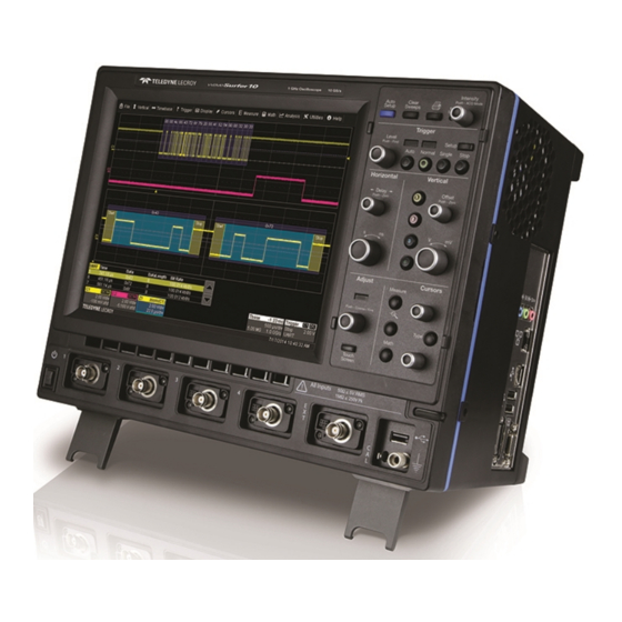
- Page 1 Operator's Manual WaveSurfer 10 Oscilloscopes...
- Page 2 However, clients are encouraged to distribute and duplicate Teledyne LeCroy documentation for their own internal educational purposes. WaveSurfer 10 and Teledyne LeCroy are trademarks of Teledyne LeCroy, Inc. Other product or brand names are trademarks or requested trademarks of their respective holders. Information in this publication supersedes all earlier versions.
-
Page 3: Table Of Contents
Operator's Manual Contents Safety Instructions Symbols Precautions Operating Environment Cooling Power Start Up Carrying and Placing the Oscilloscope Positioning the Feet Powering On/Off Software Activation Front Input/Output Panel Analog Inputs Probes Digital Inputs Side Input/Output Panel Connecting to Other Devices/Systems Touch Screen Menu Bar Grid Area... - Page 4 WaveSurfer 10 Oscilloscopes Creating Zooms Zoom Controls Vertical Channel Settings Probe Settings Auto Setup Restore Default Setup Viewing Status Timebase Timebase Settings Sampling Modes History Mode Trigger Trigger Modes Trigger Types Setting Up Triggers Trigger Holdoff Display Display Settings Persistence Cursors...
- Page 5 Operator's Manual Save Waveform Files to Memory Restore Memory Analysis WaveScan Pass/Fail Testing Utilities Utilities System Status Remote Control Settings Hardcopy (Print) Settings Auxiliary Output Settings Date/Time Settings Options Disk Utilities Preferences Settings Acquisition Settings E-Mail Miscellaneous Settings Save/Recall Save/Recall Setups Save/Recall Waveforms Save Table Data LabNotebook...
- Page 6 WaveSurfer 10 Oscilloscopes Returning a Product for Service Certifications EMC Compliance Safety Compliance Environmental Compliance ISO Certification Warranty Windows License Agreement...
- Page 7 Operator's Manual Welcome Thank you for purchasing a Teledyne LeCroy WaveSurfer Oscilloscope. We're certain you'll be pleased with the detailed features unique to our instruments. The manual is arranged in the following manner: Safety contains important precautions and information relating to power and cooling.
- Page 8 WaveSurfer 10 Oscilloscopes...
-
Page 9: Safety Instructions
Operator's Manual Safety Instructions Observe these instructions to keep the instrument operating in a correct and safe condition. You are required to follow generally accepted safety procedures in addition to the precautions specified in this section. The overall safety of any system incorporating this instrument is the responsibility of the assembler of the system. -
Page 10: Operating Environment
WaveSurfer 10 Oscilloscopes Do not operate with suspected failures. Do not use the product if any part is damaged. Obviously incorrect measurement behaviors (such as failure to calibrate) might indicate impairment due to hazardous live electrical quantities. Cease operation immediately and sequester the instrument from inadvertent use. -
Page 11: Start Up
Operator's Manual Start Up Carrying and Placing the Oscilloscope The oscilloscope’s case contains a built-in carrying handle. Lift the handle away from the oscilloscope body, grasp firmly and lift the instrument. Always unplug the instrument from the power source before moving it. Place the instrument where it will have a minimum 15 cm (6 inch) clearance from the nearest object. -
Page 12: Software Activation
The oscilloscope operating software (firmware and standard applications) is active upon delivery. At power- up, the oscilloscope loads the software automatically. Firmware Free firmware updates are available periodically from the Teledyne LeCroy website at: teledynelecroy.com/support/softwaredownload. Registered users can receive an email notification when a new update is released. Follow the instructions on the website to download and install the software. -
Page 13: Analog Inputs
Follow the directions in the probe instruction manual to compensate the frequency response of the probes. Digital Inputs The WaveSurfer 10 is compatible with the MS-250 and MS-500 Mixed Signal hardware options for input of up- to-36 lines of digital data. For instructions, see the product documentation available from teledynelecroy.com. -
Page 14: Side Input/Output Panel
WaveSurfer 10 Oscilloscopes Side Input/Output Panel A. Audio Input/Output Line-In, Speaker, and Mic jacks connect the oscilloscope to external audio devices. B. Ethernet Port connects the oscilloscope to networks. C. USB Ports (4) allow you to connect external USB devices, such as storage drives. -
Page 15: Connecting To Other Devices/Systems
Operator's Manual Connecting to Other Devices/Systems Make all desired cable connections. After start up, configure the connections using the menu options listed below. More detailed instructions are provided later in this manual. OWER Connect the line cord rated for your country to the AC power inlet on the back of the instrument, then plug it into a grounded AC power outlet. -
Page 16: Touch Screen
WaveSurfer 10 Oscilloscopes Touch Screen The touch screen is the principal viewing and control center of the oscilloscope. The entire display area is active: use your finger or the stylus to touch, double-touch, touch-and-drag, or draw a selection box. Many controls that display information also work as “buttons”... -
Page 17: Grid Area
Operator's Manual Grid Area The grid area displays the waveform traces. Every grid is 8 Vertical divisions and 10 Horizontal divisions. The value of Vertical and Horizontal divisions depends on the Vertical and Horizontal scale of the traces that appear on the grid. By default (Auto Grid mode), the grid area will automatically divide up to three times to display channel, zoom and math traces on different grids. -
Page 18: Descriptor Boxes
WaveSurfer 10 Oscilloscopes Trigger Level at the right edge of the grid tracks the trigger voltage level. If you change the trigger level when in Stop trigger mode, or in Normal or Single mode without a valid trigger, a hollow triangle of the same color appears at the new trigger level. - Page 19 Horizontal scaling that differs from the signal Timebase. Units will be automatically adjusted for the type of trace. NOTE: On WaveSurfer 10 oscilloscopes with the WS10-ADT option installed, there will be two math functions, labeled F1 and F2 on the descriptor boxes and on the Math setup dialogs.
-
Page 20: Dialogs
WaveSurfer 10 Oscilloscopes Dialogs Dialogs appear at the bottom of the display for entering setup data. The top dialog will be the main entry point for the selected setup option. For convenience, related dialogs appear as a series of tabs behind the main dialog. -
Page 21: Turning On/Off Traces
Operator's Manual Turning On/Off Traces Analog Traces From the menu bar, choose Vertical > Channel <#> Setup to turn on the trace. To turn it off, clear the Trace On checkbox on the corresponding Channel dialog, or touch-and-hold (right-click) on the descriptor box and choose Off. -
Page 22: Annotating Traces
WaveSurfer 10 Oscilloscopes Annotating Traces The Label function gives you the ability to add custom annotations to traces that are shown on the display. Labels are numbered sequentially in the order they were created. Once placed, labels can be moved to new positions or turned off. -
Page 23: Entering/Selecting Data
Operator's Manual Entering/Selecting Data Touch Touch once to activate a control. In some cases, you’ll immediately see a pop-up menu of options. Touch one to select it. TIP: You can touch the Icon or List buttons where they appear on larger pop-ups to change how menu options are displayed. -
Page 24: Printing/Screen Capture
WaveSurfer 10 Oscilloscopes Touch & Drag Touch-and-drag cursor lines and annotation labels to reposition them on the grid; this is the same as setting the values on the dialog. Touch-and-drag to draw a selection box around part of a trace to quickly zoom that portion. -
Page 25: Oscilloscope Application Window
Operator's Manual Oscilloscope Application Window The oscilloscope application runs on a Windows operating system and functions exactly as do other Windows applications. To minimize the application window and show the Windows desktop, choose File > Minimize. To restore the window after minimizing, touch the oscilloscope display icon in the lower right corner of the desktop. To exit the application window, choose File >... -
Page 26: Front Panel
WaveSurfer 10 Oscilloscopes Front Panel Most front panel controls duplicate functionality available through the touch screen display and are described on the following pages. Many knobs on the front panel function one way if turned and another if pushed like a button. When a knob is multi-plexed, the top label describes the knob’s “turn”... -
Page 27: Horizontal Controls
Operator's Manual Single sets Single trigger mode, which arms the oscilloscope to trigger once (single-shot acquisition) when the input signal meets the trigger conditions set for the type of trigger selected. If the scope is already armed, it will force a trigger. Stop prevents the oscilloscope from triggering on a signal. -
Page 28: Adjust
WaveSurfer 10 Oscilloscopes Cursor knobs reposition the selected cursor line when turned. Each knob controls one line. Push the knob resets the cursor to the default position. When both Horizontal and Vertical cursors are displayed, each knob controls two lines, and pushing the knob switches the line that is being controlled. -
Page 29: Zooming Waveforms
Operator's Manual Zooming Waveforms The Zoom function magnifies a selected region of a trace. On WaveSurfer 10 model oscilloscopes, you can display up to four zoom traces (Z1-Z4) taken from any channel, math, or memory trace. Creating Zooms To create a zoom, touch -and-drag to draw a selection box around any part of the source waveform. -
Page 30: Zoom Controls
Segment Controls These controls are used in Sequence Sampling Mode. They are only displayed on WaveSurfer 10 oscilloscopes with the WS10-ADT option installed. Zoom Factor Controls These controls on the Zx dialogs appear throughout the oscilloscope software: Out and In buttons increase or decrease the magnification of the zoom, and consequently change the Horizontal and Vertical Scale settings. - Page 31 Operator's Manual Var. checkbox enables variable zooming in increments finer than the default 1, 2, 5, 10 step increments. When checked, each touch of the zoom control buttons changes the degree of magnification by a single increment. Horizontal Scale/div sets the amount of time represented by each horizontal division of the grid. It is the equivalent of Time/div, only unlike the Timebase setting, it may be set differently for each zoom, math function, or memory trace.
-
Page 32: Vertical
Pre-Processing Settings to set up pre-acquisition processes that will affect the waveform, such as noise filtering and interpolation. If a Teledyne LeCroy probe is connected to the channel, a Probe dialog appears behind the Cx dialog. Channel Settings Volts/div sets the vertical scale (aka gain or sensitivity). -
Page 33: Probe Settings
Probe Settings When a Teledyne LeCroy-compatible probe is connected to the oscilloscope input, the probe is automatically identified and the model name displayed on the Channel dialog under the "Probe" heading. Also, the Probe dialog bearing the probe name is added to the right of the Channel dialog. -
Page 34: Auto Setup
Auto Zero corrects for DC offset drifts that naturally occur from thermal effects in the amplifier of active probes. Teledyne LeCroy probes incorporate Auto Zero capability to remove the DC offset from the probe's amplifier output to improve the measurement accuracy. -
Page 35: Viewing Status
Operator's Manual Viewing Status All oscilloscope settings can be viewed through the various Status dialogs. These show all existing acquisition, trigger, channel, math function, measurement and parameter configurations, as well as which are currently active. Access the Status dialogs by choosing the Status option from the Vertical, Timebase, Math menus (e.g., Channel Status, Acquisition Status). -
Page 36: Timebase
WaveSurfer 10 Oscilloscopes Timebase Timebase, also known as Horizontal, settings control the trace along the X axis. The timebase is shared by all channels. The time represented by each horizontal division of the grid, or Time/Division, is most easily adjusted using the front panel Horizontal knob. -
Page 37: Sampling Modes
Operator's Manual Active Channels These settings enable you to control the distribution of memory to achieve longer acquisitions through a single channel if needed. 4 (or 2 in 2 channel scopes) utilizes the per channel maximum memory (10 Mpts/ch standard, 16 Mpts/ch with the WS10-ADT option). - Page 38 Sequence Sampling Mode Sequence sampling mode is available on WaveSurfer 10 oscilloscopes with the WS10-ADT option installed. In Sequence Mode, the complete waveform consists of a number of fixed-size segments (see the instrument specifications at teledynelecroy.com for the limits). The oscilloscope uses the sequence timebase setting to determine the capture duration of each segment as 10 x time/div.
- Page 39 Operator's Manual EQUENCE When setting up Sequence Mode, you define the number of fixed-size segments acquired in single-shot mode (see the instrument specifications for the limits). The oscilloscope uses the sequence timebase setting to determine the capture duration of each segment. Along with this setting, the oscilloscope uses the number of segments, maximum segment length, and total available memory to determine the actual number of samples or segments, and time or points.
-
Page 40: History Mode
"Channel data is not continuous in ROLL mode!!!" and rolling starts again. History Mode History Mode is available on WaveSurfer 10 oscilloscopes with the WS10-ADT option installed. History Mode allows you to review any acquisition saved in the oscilloscope's history buffer, which automatically stores all acquisition records until full. - Page 41 Operator's Manual 1. Choose Timebase > History Mode. 2. Press the front panel History Mode button, or choose Timebase > History Mode. 3. Select View History to enable the history display, and View Table to display the index of records. Optionally, select to show Relative Times on the table.
-
Page 42: Trigger
WaveSurfer 10 Oscilloscopes Trigger While the oscilloscope is continuously sampling signal when it is turned on, it can only display up to its maximum memory in data samples. Triggers select an exact event/time in the waveform to display on the oscilloscope screen so that memory is not wasted on insignificant periods of the signal. -
Page 43: Trigger Types
The options for the B event depend on the type of A event. If A is a digital Pattern or PatState, B can only be an Edge. NOTE: This functionality is identical to Teledyne LeCroy's previous Qualify and State triggers, but presented through a different user interface. -
Page 44: Setting Up Triggers
WaveSurfer 10 Oscilloscopes SlewRate triggers when the rising or falling edge of a pulse crosses an upper and a lower level. The pulse edge must cross the thresholds faster or slower than a selected period of time. Serial Triggers The Serial trigger type will appear if you have installed protocol-specific serial data trigger and decode options. - Page 45 Operator's Manual Edge Trigger Edge triggers upon a achieving a certain voltage level in the positive or negative slope of the waveform. It is the default trigger selection on standard oscilloscopes. NOTE: Alternatively, you may choose a Slope of Window and enter the Upper Level and Lower Level voltage that define the window.
- Page 46 WaveSurfer 10 Oscilloscopes Width Trigger Width triggers upon finding a positive- or negative-going pulse width when measured at the specified voltage level. On the Trigger dialog, select Width trigger type to display the controls. 1. Choose the Source input. 2. Choose the type of signal Coupling at the input. Choices are: DC - All the signal’s frequency components are coupled to the trigger circuit for high frequency...
- Page 47 Operator's Manual Qualified Trigger Qualified arms the trigger on the A event, then fires on the B event. In Normal trigger mode, it automatically resets after the B event. The options for the B event depend on the type of A event. You may apply additional Holdoff by time or number of events.
- Page 48 WaveSurfer 10 Oscilloscopes Pattern Trigger Pattern is the default trigger when the Mixed Signal option is connected to the oscilloscope, as these users generally wish to find and trigger upon digital logic patterns. However, a Pattern trigger can also be set on a user-defined pattern of High or Low voltage levels in analog channels (including the External Trigger input), or a combination of digital and analog patterns when Mixed Signal capabilities are available.
- Page 49 Operator's Manual TV Trigger TV triggers on a specified line and field in standard (PAL, SECAM, NTSC, HDTV) or custom composite video signals. On the Trigger dialog, select TV trigger type to display the controls. 1. Choose the Source signal input. 2.
- Page 50 WaveSurfer 10 Oscilloscopes Glitch Trigger Glitch triggers upon finding a pulse-width that is less than a specified time or within a specified range of times. On the Trigger dialog, select Smart trigger type, then Glitch to display the controls. 1. Choose the Source signal input.
- Page 51 Operator's Manual Interval Trigger Interval triggers upon finding a specific interval, the time (period) between two consecutive edges of the same polarity: positive to positive or negative to negative. Use the interval trigger to capture intervals that fall short of, or exceed, a specified range. On the Trigger dialog, select Smart trigger type, then Interval to display the controls.
- Page 52 WaveSurfer 10 Oscilloscopes Dropout Trigger Dropout triggers when a signal loss is detected. The trigger is generated at the end of the timeout period following the last edge transition that meets the trigger conditions. It is used primarily in single-shot applications with a pre-trigger delay.
- Page 53 Operator's Manual Runt Trigger Runt triggers when a pulse crosses a first threshold, but fails to cross a second threshold before re-crossing the first. Other defining conditions for this trigger are the polarity and runt interval (width). On the Trigger dialog, select Smart trigger type, then choose Runt to display the controls. 1.
- Page 54 WaveSurfer 10 Oscilloscopes SlewRate Trigger SlewRate triggers when the rising or falling edge of a pulse crosses an upper and a lower level. The pulse edge must cross the thresholds faster or slower than a selected period of time. On the Trigger dialog, select Smart trigger type, then Slew Rate to display the controls.
-
Page 55: Trigger Holdoff
Operator's Manual Trigger Holdoff The trigger holdoff function is available on WaveSurfer 10 oscilloscopes with the WS10-ADT option installed. Holdoff is an additional condition that may be set for Edge and Pattern triggers. It can be expressed either as a period of time or an event count. Holdoff disables the trigger temporarily, even if the trigger conditions are met, until the holdoff conditions are also met. - Page 56 WaveSurfer 10 Oscilloscopes In the figure below, the bold edges on the trigger source indicate that a positive slope has been selected. The broken, upward-pointing arrows indicate potential triggers, while the bold ones show where triggers actually occur after the holdoff expires.
-
Page 57: Display
Operator's Manual Display Display settings affect the number and style of grids that appear on screen and some of the visual characteristics of traces, such as persistence. By default, the oscilloscope has Auto Grid enabled. This divides the screen into a maximum of three grids, one each for channels/memories, math functions, and zooms. -
Page 58: Persistence
WaveSurfer 10 Oscilloscopes XY displays plot the phase shift between otherwise identical signals. They can be used to display either voltage or frequency on both axes, each axis now corresponding to a different signal input, rather than a different parameter. The shape of the resulting pattern reveals information about phase difference and frequency ratio. - Page 59 Operator's Manual example, down at the noise level) could be of greater interest to you than the rest. The Analog persistence view highlights the distribution of data so that you can examine it in detail. Color Mode persistence works on the same principle as Analog persistence, but instead uses the entire color spectrum to map signal intensity: violet for minimum population, red for maximum population.
-
Page 60: Cursors
WaveSurfer 10 Oscilloscopes Cursors Cursors are markers (lines or cross-hairs) that identify specific voltage and time values on the waveform. Use cursors to make fast, accurate measurements of specific points in the waveform. There are three, standard cursor types available. -
Page 61: Cursor Settings
Operator's Manual Cursor Settings Display Cursors To quickly turn on/off cursors, either: From the menu bar, choose Cursors then select the desired cursor type from the drop-down list. On the front panel, press the Cursor Type button repeatedly to cycle through all the cursor types. Stop when the desired type is displayed. -
Page 62: Measure
WaveSurfer 10 Oscilloscopes Measure Measurement parameters are tools that give you access to a wide range of waveform properties. Use them to analyze many attributes of your waveform such as rise-time, rms voltage, and peak-to-peak voltage. You can create a custom set of up to six parameters drawn from all the standard measurements, as well as specialized measurements installed with optional software packages. - Page 63 To reset the statistics counter, touch Clear Sweeps on the display or front panel. Viewing Histicons The histicon capability is available on WaveSurfer 10 oscilloscopes with the WS10-ADT option installed. Histicons are miniature histograms of measurement parameters that appear on the measurement table.
-
Page 64: List Of Standard Measurements
WaveSurfer 10 Oscilloscopes List of Standard Measurements Measurements included standard with the oscilloscope are listed below alphabetically. NOTE: There may be additional parameters available depending on the software options installed on the oscilloscope. Measurement Description Measures the difference between upper and lower levels in two-level signals. Differs from pkpk in that noise, Amplitude overshoot, undershoot, and ringing do not affect the measurement. - Page 65 Operator's Manual Measurement Description The time between every other pair of 50% crossings. Starting with first transition after left measurement gate, Period period is measured for each transition pair, with values averaged to give final result. Phase difference between signal analyzed and signal used as reference. Both signals are measured from the Phase 50% point of their rising edges.
-
Page 66: Calculating Measurements
WaveSurfer 10 Oscilloscopes Calculating Measurements Determining Top and Base Lines Proper determination of the top and base reference lines is fundamental for ensuring correct parameter calculations. The analysis begins by computing a histogram of the waveform data over the time interval spanned by the left and right measurement gates. - Page 67 Operator's Manual Where Mr is the number of leading edges found, Mf the number of trailing edges found, the time when rising edge i crosses the x% level, and the time when falling edge i crosses the x% level. Determining Time Parameters Time parameter measurements such as width, period and delay are carried out with respect to the mesial reference level, located halfway (50%) between the top and base reference lines.
-
Page 68: Math
WaveSurfer 10 Oscilloscopes Math Math traces ) display the result of applying a mathematical operation to a source trace. The output of a math function is always another trace, whereas the output of a measurement parameter is a tabular readout of the measurement. -
Page 69: Set Up Math Function
NOTE: You can set up two, single- or dual-operator math functions on WaveSurfer 10 oscilloscopes with the WS10-ADT option installed. Use the F1 and F2 dialogs to configure the functions; use the Math dialog to enable/disable them. -
Page 70: List Of Standard Operators
WaveSurfer 10 Oscilloscopes There will also be a Zoom dialog where you can adjust the math trace Vertical range. This does not affect the scale of any other traces. List of Standard Operators The math operators included standard with your oscilloscope are listed below alphabetically. -
Page 71: Advanced Debut Toolkit Math Functions
Operator's Manual Operator Definition Roof Calculates the highest vertical values of a waveform at each horizontal value for a specified number of sweeps. Square For every point in the waveform, the square of the sample value is calculated. Square Root For every point in the waveform, the square root of the sample value is calculated. -
Page 72: Fft
WaveSurfer 10 Oscilloscopes For a large class of signals, you can gain greater insight by looking at spectral representation rather than time description. Signals encountered in the frequency response of amplifiers, oscillator phase noise and those in mechanical vibration analysis, for example, are easier to observe in the frequency domain. - Page 73 Operator's Manual Choosing a Window The choice of a spectral window is dictated by the signal's characteristics. Weighting functions control the filter response shape, and affect noise bandwidth as well as side lobe levels. Ideally, the main lobe should be as narrow and flat as possible to effectively discriminate all spectral components, while all side lobes should be infinitely attenuated.
-
Page 74: Averaging Waveforms
WaveSurfer 10 Oscilloscopes Averaging Waveforms Summed Averaging Summed Averaging is the repeated addition, with equal weight, of successive source waveform records. If a stable trigger is available, the resulting average has a random noise component lower than that of a single- shot record. -
Page 75: Enhanced Resolution
Operator's Manual 6 th sweep: new average = (new data + 4 * old average)/(4 + 1) = 1/5 new data + 4/5 old average 7 th sweep: new average = (new data + 4 * old average)/(4 + 1) = 1/5 new data + 4/5 old average In this way, for sweeps >... - Page 76 WaveSurfer 10 Oscilloscopes How the Instrument Enhances Resolution The instrument's enhanced resolution feature improves vertical resolution by a fixed amount for each filter. This real increase in resolution occurs whether or not the signal is noisy, or your signal is single-shot or repetitive.
- Page 77 Operator's Manual would be incorrect. This is because in some circumstances an overflow may be a spike of only one or two samples, and the energy in this spike may not be enough to significantly affect the results. It would then be undesirable to disallow the whole trace.
-
Page 78: Rescaling And Assigning Units
WaveSurfer 10 Oscilloscopes lengths. Data is lost at the start and end of the waveform and the trace ends up slightly shorter after filtering. The number of samples lost is exactly equal to the length of the impulse response of the filter used: between 2 and 117 samples. - Page 79 Operator's Manual Abbreviated Units of Measure Abbreviation Measure Abbreviation Measure (blank) No units Newton Ampere Coulomb Pascal CYCLE Cycles Percent Decibel POISE Poise Decibel referred to carrier Parts per million Decibel Milliwatt Radian Decibel Volts Degree (of arc) DBUZ Decibel Microamp Minute (of arc) Decade SAMPLE...
-
Page 80: Trend
WaveSurfer 10 Oscilloscopes Trend A Trend is a plot composed of a series of parameter measurements in the order the measurements were taken. The vertical units are those of the source parameter, the horizontal unit is measurement number. The Trend contains a single value for each measurement. Trends are especially useful for visualizing the history of a parameter over an extended period of time or over multiple acquisitions. -
Page 81: Memory
Save Waveform Files to Memory Trace (.trc) files saved on other Teledyne LeCroy oscilloscopes can also be stored to internal memory. Use Recall Waveform function to save external files to memory. Then, you can use the Memories dialog to... -
Page 82: Restore Memory
WaveSurfer 10 Oscilloscopes Restore Memory 1. Access the Memories dialog by pressing the front panel Mem button or choosing Math > Memory Setup. 2. Check On next to the memory you wish to display. A description of the memory showing the source... -
Page 83: Analysis
Operator's Manual Analysis Most Teledyne LeCroy oscilloscopes calculate measurements for all instances in the acquisition, enabling you to rapidly and thoroughly analyze a long memory acquisition of thousands or millions of parameter values, or to apply a variety of mathematical functions to the waveform trace. - Page 84 WaveSurfer 10 Oscilloscopes Customize the presentation by choosing different WaveScan display features, or Scan Views. Optionally, set Actions to occur automatically when unusual events are found, such as stopping the acquisition or sounding an alarm. NOTE: Whenever WaveScan is enabled, the instrument reverts to Real-time sampling mode.
- Page 85 Operator's Manual In the case of negative-going runt pulses, the value displayed in the table is the difference (delta) of the high level of the signal and the runt amplitude (i.e., where the runt bottoms out). This can be confirmed by placing cursors on the runt pulse and reading the delta Y value in the trace labels.
- Page 86 WaveSurfer 10 Oscilloscopes Zoom view works exactly as it does elsewhere in the oscilloscope software, opening a close-up of the source trace in a new grid that you can adjust vertically and horizontally. A Zx tab appears by default when you launch WaveScan;...
-
Page 87: Pass/Fail Testing
Operator's Manual Pass/Fail Testing Pass/Fail testing is a type of mask testing that is particularly useful for comparing newly acquired signals to a previously acquired "golden standard" waveform. A mask defines an area of the grid against which a source Channel, Zoom, or Math trace is compared. Test conditions are associated with the mask, defining how the waveform is to be compared to the masked area (e.g., some/all values fall within, some/all values fall outside), and a Pass or Fail result is returned indicating the condition was found to be true or false. - Page 88 WaveSurfer 10 Oscilloscopes 2. If desired, enter a new Destination File Name and path, or touch Browse and select a previous file to overwrite. The file name should end with the .msk extension. 3. Touch the Ver Delta and Hor Delta fields and enter boundary values using the pop-up numeric keypad or the front panel Adjust knob.
- Page 89 Operator's Manual Define Test 1. Touch More to display the Test tab, then open the Test dialog. 2. Select one of the conditions that, when True (yes), result in a Pass. 3. Optionally, turn Off/On markers. Markers visually indicate where on the waveform mask violations have occurred.
-
Page 90: Utilities
The Service button to the far right of the dialog launches a section of the application reserved for qualified Teledyne LeCroy service personnel. An access code is required to enter this section. System Status The Utilities Status dialog displays information about your instrument including model number, serial number, firmware version, and installed hardware and software options. -
Page 91: Remote Control Settings
The Remote dialog contains settings to configure remote control of the instrument. Supported protocols are: TCPIP (Ethernet). If you choose this option, also install Teledyne LeCroy's VICP drivers on the controller. These are included in the VICP Passport plug-in, available free from teledynelecroy.com. - Page 92 WaveSurfer 10 Oscilloscopes Set Up Remote Control 1. From the menu bar, choose Utilities > Utilities Setup, then touch the Remote tab. 2. On the Remote dialog, make a Control From selection. 3. If using TCPIP or LXI, touch the Net Connections button and select a network from the pop-up.
-
Page 93: Hardcopy (Print) Settings
Operator's Manual Hardcopy (Print) Settings Hardcopy settings control how the oscilloscope Print function behaves. Print captures an image of the oscilloscope display, but there are several options as to what it does with the image next: Send to a hardcopy printer "Print"... - Page 94 WaveSurfer 10 Oscilloscopes RINT ETUP 1. On the Hardcopy dialog, choose Printer. 2. Touch Select Printer and choose a printer from the list. If you don't see the printer you want, first follow steps to Add Printer. 3. Choose a page Orientation: portrait or landscape.
- Page 95 Operator's Manual Send to E-Mail Follow this procedure to e-mail capture files to a preset address. The e-mail connection is set up in Utilities > Preferences Setup > E-Mail. 1. On the Hardcopy dialog, choose E-Mail. 2. Choose the output File Format. 3.
-
Page 96: Auxiliary Output Settings
WaveSurfer 10 Oscilloscopes Auxiliary Output Settings Use the Aux Output dialog to configure the output of the Aux Out and Cal Out ports. Use the Aux Output dialog to configure the output of the Aux Out port. The port outputs a 1.0 V TTL pulse following the selected event. -
Page 97: Date/Time Settings
Operator's Manual Date/Time Settings Date/Time settings control the oscilloscope's timestamp. These numbers appear in the oscilloscope message bar and on tables/records internal to the oscilloscope application, such as History Mode and WaveScan. NOTE: This is not the same as the Timebase reference clock used to synchronize traces. To access the Date/Time dialog, choose Utilities >... -
Page 98: Disk Utilities
WaveSurfer 10 Oscilloscopes Disk Utilities Use the Disk Utilities dialog to manage files and folders on your instrument's hard drive. Disk Space information is shown at the far right of the dialog for convenience. NOTE: These tasks can also be accomplished using the standard Microsoft Windows file management tools. -
Page 99: Preferences Settings
Operator's Manual Preferences Settings Preference settings have mostly to do with the appearance and performance of the oscilloscope itself, rather than the oscilloscope's interaction with other devices/systems. Access the Preferences dialog by choosing Utilities > Preference Setup... from the menu bar. Audible Feedback controls the instrument's audio output. -
Page 100: Acquisition Settings
WaveSurfer 10 Oscilloscopes Acquisition Settings The Acquisition settings determine how traces behave on screen as gain or timebase changes. Offset Setting constant in: Volts moves the vertical offset level indicator with the actual voltage level. Div(isions) keeps the vertical offset level indicator stationary. The waveform remains on the grid as you increase the gain;... -
Page 101: E-Mail
Operator's Manual E-Mail Use the E-mail dialog to set up e-mail on the oscilloscope. 1. Under E-Mail Server, select the protocol used by your network: MAPI (Messaging Application Programming Interface) is the Microsoft interface specification that allows different messaging and workgroup applications (including e-mail, voice mail, and fax) to work through a single client, such as the Exchange client. -
Page 102: Miscellaneous Settings
Miscellaneous Settings These other Preference settings are located on the Miscellaneous dialog. To add the Teledyne LeCroy logo to print output, check Print Teledyne LeCroy Logo When Printing Grid Area Only. This identifies the instrument as the source of the image. -
Page 103: Save/Recall
Operator's Manual Save/Recall The oscilloscope File menu allows you to save or retrieve waveform files, measurement table data, and instrument setup panels. Access these functions by choosing any of the Save or Recall options from the File menu. The dialog contains a tab for each file function. - Page 104 WaveSurfer 10 Oscilloscopes Recalling Oscilloscope Setups Choose File > Recall Setup... from the menu bar. ECALL ETUP EMORY Touch one of the six Recall buttons under Recall From Internal Setup..NOTE: If a setup has been stored to a location, it is labeled with the save date/time. Otherwise, the slot is labeled Empty.
-
Page 105: Save/Recall Waveforms
Operator's Manual Save/Recall Waveforms The Save Waveform function saves trace data to either an internal memory location, or to a text or binary format file (.trc). The source waveform can be any trace; for example, a channel, math function, or a waveform stored in another memory. - Page 106 (e.g., XYZ32a). 4. Touch Data Format and select a file format: Binary, Teledyne LeCroy's binary file format (.trc). Binary results in the smallest possible file size, and is necessary for recalling waveforms to Teledyne LeCroy instruments. NOTE: Binary files can be converted to ASCII using Teledye LeCroy utilities such as ScopeExplorer or WaveStudio.
- Page 107 Operator's Manual Recall Waveform Choose File > Recall Waveform from the menu bar. NOTE: Only .trc files saved in binary format can be recalled into the oscilloscope. ECALL AVEFORM EMORY 1. Touch Memory. 2. Touch Source and choose a memory location from the Select Source pop-up. 3.
-
Page 108: Save Table Data
WaveSurfer 10 Oscilloscopes Save Table Data The Save Table function saves tabular measurement data displayed on screen to an Excel or ASCII file. By default, files are saved , although you can choose . Access the Save Table dialog by choosing File > Save Table from the menu bar. -
Page 109: Labnotebook
Operator's Manual LabNotebook Teledyne LeCroy's LabNotebook feature extends the documentation capabilities of your oscilloscope. It allows you to create and save Notebook Entries containing all displayed waveforms, the oscilloscope setup under which they were taken, and custom annotations. Notebook Entries are stored in an internal database and are available for recall at any time. Besides storing the waveform data, LabNotebook also stores your panel setups and parameter measurements. -
Page 110: Labnotebook Drawing Toolbar
WaveSurfer 10 Oscilloscopes LabNotebook Drawing Toolbar The basic Notebook Entry is a screen capture of the display showing the grids as they were at the time it was taken. When an entry is first captured, it is immediately displayed in the Drawing window for you to annotate. -
Page 111: Manage Notebook Entries
Operator's Manual Manage Notebook Entries The LabNotebook dialog is the principal notebook management tool where you can filter, select, view, edit, print, email, save, export/import, or recall Notebook Entries created in the course of your work. To access the LabNotebook dialog, choose File > LabNotebook from the menu bar. NOTE: If an external monitor is connected, LabNotebook automatically opens on the external monitor. - Page 112 WaveSurfer 10 Oscilloscopes Select the desired entries and touch the View button. Use the scrollbar that appears on the LabNotebook window to navigate the report. Edit Notebook Entries 1. Select the notebook from the My Notebooks list. 2. Select the entry from the My Notebook Entries list.
-
Page 113: Print To Notebook Entry
Operator's Manual Create Report Create Reports collates the selected Notebook Entries into a single .RTF/.PDF document or HTML archive using the report template selected on the LabNotebook Preferences tab. This can be one of the preformatted templates or a custom format. It is not necessary to first create a report document to view, email, or print selected Notebook Entries. -
Page 114: Manage Notebooks
WaveSurfer 10 Oscilloscopes Manage Notebooks LabNotebook stores Notebook Entries in a .zip archive on the instrument hard drive. Each .zip file is one Notebook comprised of everything shown in the My Notebook Entries list. New Notebooks can be created for different individuals or projects, or an existing Notebook backed up for storage. -
Page 115: Customize Reports
Operator's Manual Customize Reports The Advanced tab allows you to customize the report creation function. Change Directories To change where Notebooks are stored, change the Notebooks Directory folder. To change where reports are output, change the Report Directory folder. You can choose an external location, such as a USB drive. -
Page 116: Configure Labnotebook Preferences
WaveSurfer 10 Oscilloscopes Configure LabNotebook Preferences To configure the behavior of the LabNotebook tool, on the menu bar, choose File > Lab Notebook, then touch the Preferences tab. Select/deselect the following options: Prompt for Entry Title Before Saving opens the LabNotebook dialog when a new entry is created. You can elect to name notebook entries using only the date/timestamp by leaving this box unchecked. -
Page 117: Maintenance
Operator's Manual Maintenance Cleaning Clean only the exterior of the instrument using a soft cloth moistened with water or an alcohol solution. Do not use harsh chemicals or abrasive elements. Under no circumstances submerge the instrument or allow moisture to penetrate it. Avoid electric shock by unplugging the power cord from the AC outlet before cleaning. -
Page 118: Reboot Oscilloscope
Many optional software packages are available to extend the Analysis functions of the oscilloscope. See the product page at teledynelecroy.com for a list of options compatible with your model. Contact your local Teledyne LeCroy representative or national distributor to purchase an option. You will receive a Key Code by email that enables the new functionality. -
Page 119: X-Stream Firmware Update
Operator's Manual X-Stream Firmware Update Teledyne LeCroy frequently releases free firmware updates for X-Stream model oscilloscopes containing new product features and bug fixes. The X-Stream installer updates multiple components including the oscilloscope application, required DLLs, drivers, and low-level microcode for integrated circuits on the oscilloscope. -
Page 120: System Recovery
For this purpose, Teledyne LeCroy provides a recovery application and a backup image in an extra partition on the instrument's hard drive. The recovery process is easy to perform. - Page 121 Operator's Manual 6. Under Recovery Method, select Recover whole disks and partitions, then click Next. 7. Under What to Recover, select NTFS (SYSTEM) (C:), then click Next. 8. Under Settings of Partition C, in the top section, Partition location (required), select New Location.The Partition Destination window opens.
-
Page 122: Technical Support
Teledyne LeCroy publishes a free Technical Library on its website. Manuals, tutorials, application notes, white papers, and videos are available to help you get the most out of your Teledyne LeCroy products. The Datasheet published on the product page contains the detailed product specifications. -
Page 123: Returning A Product For Service
4. Pack the product case in a cardboard shipping box with adequate padding to avoid damage in transit. 5. Mark the outside of the box with the shipping address given to you by Teledyne LeCroy; be sure to add the following: ATTN: <RMA code assigned by Teledyne LeCroy>... -
Page 124: Contact Teledyne Lecroy
WaveSurfer 10 Oscilloscopes Contact Teledyne LeCroy Singapore Genetron Singapore Pte Ltd. United States and Canada 37 Kallang Pudding Road, #08-08 - World Wide Corporate Office Tong Lee Building Block B Teledyne LeCroy Corporation Singapore 349315 700 Chestnut Ridge Road Ph: ++ 65 9760-4682... -
Page 125: Certifications
5 Performance Criteria “C” applied for 70%/25 cycle voltage dips and 0%/250 cycle voltage interruption test levels per EN61000-4-11. UROPEAN ONTACT Teledyne LeCroy Europe GmbH Waldhofer Str 104 D-69123 Heidelberg Germany... -
Page 126: Safety Compliance
WaveSurfer 10 Oscilloscopes Australia & New Zealand Declaration of Conformity– EMC Oscilloscope complies with the EMC provision of the Radio Communications Act per the following standards, in accordance with requirements imposed by Australian Communication and Media Authority (ACMA): EN 55011:2010 Radiated and Conducted Emissions, Group 1, Class A, in accordance with EN61326-1:2013 and EN61326-2-1:2013. -
Page 127: Environmental Compliance
The instrument is subject to disposal and recycling regulations that vary by country and region. Many countries prohibit the disposal of waste electronic equipment in standard waste receptacles. For more information about proper disposal and recycling of your Teledyne LeCroy product, please visit teledynelecroy.com/recycle. -
Page 128: Warranty
Teledyne LeCroy shall not be responsible for any defect, damage, or failure caused by any of the following: a) attempted repairs or installations by personnel other than Teledyne LeCroy representatives or b) improper connection to incompatible equipment, or c) for any damage or malfunction caused by the use of non- Teledyne LeCroy supplies.