Table of Contents
Advertisement
Quick Links
Advertisement
Table of Contents

Related Manuals for Vaisala WXT536


Summary of Contents for Vaisala WXT536
- Page 1 USER'S GUIDE Vaisala Weather Transmitter WXT530 Series M211840EN-C...
- Page 2 This manual does not create any legally binding obligations for Vaisala towards customers or end users. All legally binding obligations and agreements are included exclusively in the applicable supply contract or General Conditions of Sale and General Conditions of Service of Vaisala.
-
Page 3: Table Of Contents
WXT536 ........ - Page 4 ________________________________________________________________________________ Selecting the Location ......38 Unpacking ........40 Installing the Transmitter .
- Page 5 Changing the Settings (aSU) ..... . 146 Composite Data Message (aR0) ..... 147 VAISALA ________________________________________________________________________ 3...
- Page 6 ________________________________________________________________________________ Analog Input ........149 Enabling and Disabling Analog Input ....152 Common Sensor Settings (aIU) .
- Page 7 APPENDIX F WIRING EXTERNAL SENSORS TO WXT536 ..... 207 Connecting Snow Depth Sensor to WXT536 ..208 Connecting Pyranometer to WXT536 .
- Page 8 ________________________________________________________________________________ APPENDIX G COMPLETE SET OF ACCESSORIES ......217 APPENDIX H CONFIGURATION PARAMETERS ......225 6 _______________________________________________________________________________...
- Page 9 Figure 8 Bottom of WXT536........23 Figure 9 USB Cable .
- Page 10 Wiring CMP3 to WXT53 ......213 Figure 54 Wiring RG13 to WXT536 ......215 Figure 55 Complete Set of Accessories .
- Page 11 General Unit Settings ........204 VAISALA ________________________________________________________________________ 9...
- Page 12 ________________________________________________________________________________ Table 43 Wind Configuration Settings......204 Table 44 PTU Configuration Settings ......205 Table 45 Rain Configuration Settings .
-
Page 13: General Information
GENERAL INFORMATION This chapter provides general notes for the product. About This Manual This manual provides information for installing, operating, and maintaining Vaisala Weather Transmitter WXT530 Series transmitters. General Safety Considerations Throughout the manual, important safety considerations are highlighted as follows: WARNING Warning alerts you to a serious hazard. -
Page 14: Esd Protection
Note highlights important information on using the product. ESD Protection Electrostatic Discharge (ESD) can cause immediate or latent damage to electronic circuits. Vaisala products are adequately protected against ESD for their intended use. However, it is possible to damage the product by delivering electrostatic discharges when touching, removing, or inserting any objects inside the equipment housing. -
Page 15: Recycling
United States and/or other countries. License Agreement All rights to any software are held by Vaisala or third parties. The customer is allowed to use the software only to the extent that is provided by the applicable supply contract or Software License Agreement. -
Page 16: Warranty
Electrical and Electronic Equipment (2002/95/EC) Warranty Visit our Internet pages for standard warranty terms and conditions: www.vaisala.com/warranty. Please observe that any such warranty may not be valid in case of damage due to normal wear and tear, exceptional operating conditions, negligent handling or installation, or unauthorized modifications. -
Page 17: Chapter 2 Product Overview
Chapter 2 __________________________________________________________ Product Overview CHAPTER 2 PRODUCT OVERVIEW This chapter introduces the features of the WXT530 series weather transmitters. WXT530 Series Weather Transmitters The WXT530 product family consists of six transmitters. Figure 1 Vaisala Weather Transmitter WXT530 Series 0504-066 VAISALA _______________________________________________________________________ 15... - Page 18 Fire weather Meteorological test beds Noise monitoring Researchers Sport events Weather stations The WXT530 product family offers a variety of weather parameters. The measurement combinations of each model are listed below. WXT536 WXT535 WXT534 WXT533 WXT532 WXT531 Pressure Temperature Humidity...
-
Page 19: Table 54 Table
The following table shows different options available for the product family. Table 1 Available Options Available options WXT536 WXT535 WXT534 WXT533 WXT532 WXT531 Service Pack 2: Windows based Vaisala Configuration Tool software with USB service cable (1.4 m) USB RS-232/RS-485 cable (1.4 m) -
Page 20: Wxt536
User’s Guide ______________________________________________________________________ WXT536 WXT536 measures pressure, temperature, humidity, rain, wind speed, and wind direction. It offers an analog input option. Figure 2 WXT536 Analog input 18 __________________________________________________________________ M211840EN-C... -
Page 21: Wxt535 And Wxt534
Chapter 2 __________________________________________________________ Product Overview WXT535 and WXT534 WXT535 measures pressure, temperature, humidity, and rain. WXT534 measures pressure, temperature, and humidity. Figure 3 WXT535 and WXT534 VAISALA _______________________________________________________________________ 19... -
Page 22: Wxt533 And Wxt532
User’s Guide ______________________________________________________________________ WXT533 and WXT532 WXT533 measures rain and wind. WXT532 measures wind and it offers an mA output option. Figure 4 WXT533 and WXT532 WXT531 WXT531 measures rain. Figure 5 WXT531 1508-125 20 __________________________________________________________________ M211840EN-C... -
Page 23: Components
Chapter 2 __________________________________________________________ Product Overview Components Figure 6 WXT536 Components 1508-118 Fixing screw and chassis grounding point Screw cover Top of the transmitter Radiation shield Bottom of the transmitter VAISALA _______________________________________________________________________ 21... -
Page 24: Figure 7 Cut-Away View Of Wxt536
User’s Guide ______________________________________________________________________ Figure 7 Cut-Away View of WXT536 1508-124 Wind transducers (3 pcs) Precipitation sensor Pressure sensor inside the PTU module Humidity and temperature sensors inside the PTU module Service port 22 __________________________________________________________________ M211840EN-C... -
Page 25: Figure 8 Bottom Of Wxt536
Chapter 2 __________________________________________________________ Product Overview Figure 8 Bottom of WXT536 1508-122 Opening for cable gland (if unused, cover with a hexagonal plug). Watertight cable gland (optional, included in the Bushing and Grounding Kit) 4-pin M8 connector for Service Port 8-pin M12 connector for power or data communications cable... -
Page 26: Optional Features
User’s Guide ______________________________________________________________________ Optional features The WXT530 series includes the following optional features. For a complete list, see Table 40 on page 179. Note that you must select these options when placing the order. USB Cables Figure 9 USB Cable 1509-029 USB RS-232/RS-485 cable with 8-pin M12 threaded connector (1.4 m) -
Page 27: Mounting Kit
When using the optional mounting kit, alignment is needed only when mounting for the first time. Using the mounting kit also improves the IP classification of the transmitter to IP66. Without the mounting kit, the WXT530 series transmitters are IP65 rated. VAISALA _______________________________________________________________________ 25... -
Page 28: Surge Protector
Vaisala provides the following surge protectors: Vaisala Surge Protector WSP150. A compact transient overvoltage suppressor designed for outdoor use. It can be used with all Vaisala wind and weather instruments. Install WSP150 close to the protected instrument (maximum 3 m). Vaisala Surge Protector WSP152. -
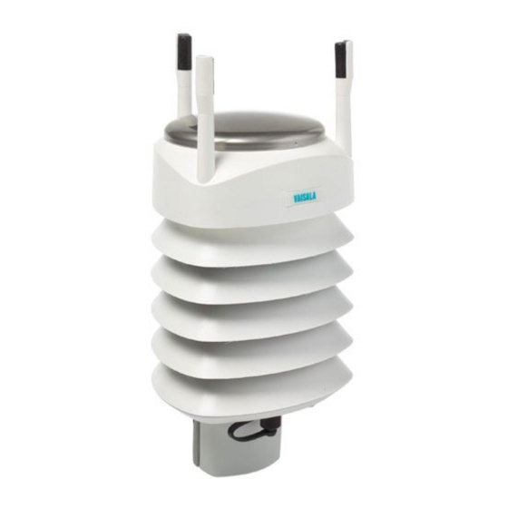
Page 29: Bird Spike Kit
The kit consists of a metallic band with spikes pointing upward. The kit is installed on top of the transmitter. The shape and location of the spikes has been designed so that the interference with wind and rain measurement is minimal. Figure 13 WXT536 with Bird Spike Kit 1509-065 VAISALA _______________________________________________________________________ 27... -
Page 30: Vaisala Configuration Tool
Note that when the kit is in place, more snow can accumulate on the transmitter, and the snow can melt away more slowly. Vaisala Configuration Tool Vaisala Configuration Tool is a Windows-based, user-friendly parameter setting software for the WXT530 Series transmitters. Using this software tool, you can change the device and sensor settings easily in Windows environment. -
Page 31: Functional Description
WXT534 WXT533 WXT532 WXT531 The transmitters use Vaisala WINDCAP sensor technology for wind measurement. The wind sensor has an array of three equally spaced ultrasonic transducers on a horizontal plane. The unit determines wind speed and wind directions by measuring the time it takes the ultrasound to travel from one transducer to the other two. - Page 32 User’s Guide ______________________________________________________________________ The unit calculates wind speed from the measured transit times using the following formula: 0505-216 where Wind speed Distance between the two transducers Transit time in forward direction Transit time in reverse direction Measuring the six transit times allows V to be computed for each of the three ultrasonic paths.
- Page 33 If poor quality is detected, the wind values are marked as invalid. If over half of the measurement values are considered invalid, the last valid wind values are returned as missing data. However, in the SDI-12 protocol, the invalid values are marked as zero (0). VAISALA _______________________________________________________________________ 31...
-
Page 34: Precipitation Measurement Principle
WXT534 WXT533 WXT532 WXT531 The transmitter uses Vaisala RAINCAP Sensor 2-technology in precipitation measurement. The precipitation sensor comprises of a steel cover and a piezoelectrical sensor mounted on the bottom surface of the cover. The precipitation sensor detects the impact of individual raindrops. The signals from the impact are proportional to the volume of the drops. - Page 35 Transmitter sends automatically a precipitation message in the update intervals defined by the user. Polled mode: Transmitter sends a precipitation message whenever requested by the user. For details about the precipitation sensor operation, see Precipitation Sensor on page 138. VAISALA _______________________________________________________________________ 33...
-
Page 36: Ptu Measurement Principle
User’s Guide ______________________________________________________________________ PTU Measurement Principle WXT536 WXT535 WXT534 WXT533 WXT532 WXT531 The PTU module contains separate sensors for pressure, temperature, and humidity measurement. The measurement principle of the transmitter is based on an advanced RC oscillator and two reference capacitors against which the capacitance of the sensors is continuously measured. - Page 37 When the heating function is disabled, the heating is off in all conditions. See Supervisor Message on page 144. NOTE Snow accumulation can cause temporary wind measurement problems even when heating is enabled. VAISALA _______________________________________________________________________ 35...
-
Page 38: Analog Input Interface
Analog Input Interface WXT536 WXT535 WXT534 WXT533 WXT532 WXT531 WXT536 offers an analog input option for solar radiation, external temperature, level measurement, and tipping bucket. Table 3 Analog Inputs for External Sensors Analog input 1 Sensor A Solar radiation Analog input 2... -
Page 39: Chapter 4 Installation
The transmitter must be installed in open space to avoid disturbance in measurements. Do not place the transmitter directly in front of a radar. Do not install the transmitter next to a powerful RF-transmitter antenna. VAISALA _______________________________________________________________________ 37... -
Page 40: Selecting The Location
User’s Guide ______________________________________________________________________ Selecting the Location Following WMO guidelines, select a site that represents the general area of interest to ensure representative ambient measurements. Make sure that the site that is free from turbulence caused by nearby objects, such as trees and buildings. In general, any object of height (h) does not significantly disturb wind measurement at a minimum distance of 10 times the height of the object. -
Page 41: Figure 15 Recommended Mast Length On Top Of Building
Additional protection is needed in regions with frequent, severe thunderstorms, especially when long line cables (> 30 m) are used. Vaisala recommends using a surge protector, such as WSP150 and WSP152, in all sites with an elevated risk of lightning strike. -
Page 42: Unpacking
User’s Guide ______________________________________________________________________ Unpacking The transmitter comes in a custom shipping container. The figure below shows the contents of the carton. Figure 16 Contents of Shipping Container Protective packaging top Shipping carton Inner box Manual, cables, mounting kit (optional) Installation note Protective packaging bottom Transmitter Bird kit (optional) -
Page 43: Figure 17 Installing With Protective Packaging
Be careful not to damage the wind transducers located at the top of the three antennas. Dropping the device can break or damage the transducers. If the antenna bends or twists, re-aligning can be difficult or impossible. NOTE Save the container and the packaging materials for future transportation and shipping. VAISALA _______________________________________________________________________ 41... -
Page 44: Installing The Transmitter
User’s Guide ______________________________________________________________________ Installing the Transmitter At the measurement site, you must mount, ground, align, and connect the transmitter to the data logger and the power source. WARNING To protect personnel and the device, install a lightning rod with the tip at least one meter above the transmitter. -
Page 45: Mounting On Vertical Pole Mast
Remove the screw cover and insert the transmitter to the pole mast. Figure 18 Removing Screw Cover Align the transmitter so that the arrow points to north. Figure 19 North Arrow 1509-084 Tighten the fixing screw and replace the screw cover. VAISALA _______________________________________________________________________ 43... -
Page 46: Mounting On Vertical Pole Mast With Mounting Kit
User’s Guide ______________________________________________________________________ Mounting on Vertical Pole Mast with Mounting Kit When mounting a transmitter on a pole mast, you can use an optional mounting kit to ease mounting. Figure 20 Mounting WXT531 on Vertical Pole Mast 1509-083 To mount a transmitter on a vertical pole mast with the mounting kit: Insert the mounting kit adapter to the transmitter bottom. -
Page 47: Figure 21 Mounting Transmitter With Mounting Kit
Mount the adapter to the pole mast but do not tighten the fixing screw. Align the transmitter so that the arrow on the bottom of the transmitter points north. Tighten the fixing screw of the mounting adapter to attach the adapter firmly to the pole mast. VAISALA _______________________________________________________________________ 45... -
Page 48: Figure 22 Removing Protective Cushion After Installation
User’s Guide ______________________________________________________________________ Remove the protective cushion. Figure 22 Removing Protective Cushion after Installation 1509-031 NOTE When removing a transmitter from the pole, turn the transmitter so that it snaps out from the mounting kit. Realignment is not needed when replacing the device. -
Page 49: Mounting On Horizontal Cross Arm
Wind Direction Offset on page Mount the transmitter on the cross arm using a mounting bolt (M6 DIN933) and a nut (M6 DIN934). Figure 23 Mounting Transmitter to Cross Arm (L-Profile) 1509-067 Nut (M6 DIN934) Mounting bolt (M6 DIN933) Screw cover VAISALA _______________________________________________________________________ 47... -
Page 50: Grounding
User’s Guide ______________________________________________________________________ Figure 24 Mounting Bolt Location in Cross Arm 1509-066 Nut (M6 DIN934) Mounting bolt (M6 DIN933) Grounding A transmitter is typically grounded by installing it on a mast or a cross arm that provides a good connection to earth ground. As grounding is provided through the fixing screw (or mounting bolt), it is important that it makes a good ground connection. -
Page 51: Aligning
Abiko connector between two washers Aligning WXT536 WXT535 WXT534 WXT533 WXT532 WXT531 To help the alignment, there is an arrow and the text "North" on the bottom of the transmitter. Align the transmitter so that this arrow points north. VAISALA _______________________________________________________________________ 49... -
Page 52: Compass Alignment
User’s Guide ______________________________________________________________________ Wind direction can be referred either to true north, which uses the Earth’s geographic meridians, or to the magnetic north, which is read with a magnetic compass. The magnetic declination is the difference in degrees between the true north and magnetic north. The source for the magnetic declination should be current as the declination changes over time. -
Page 53: Wind Direction Offset
Enter the deviation angle in the device using the wind message formatting command aWU,D (direction offset). See Checking the Settings (aWU) on page 127. Now the transmitter transmits the wind direction data by using the changed zero-alignment. VAISALA _______________________________________________________________________ 51... - Page 54 User’s Guide ______________________________________________________________________ 52 __________________________________________________________________ M211840EN-C...
-
Page 55: Wiring And Power Management
8-pin M12 connector. Only one serial interface can be used at a time. CAUTION The cable opening in the transmitter bottom assembly is covered with hexagonal rubber plugs. If you are not using the cable gland (included in the Bushing and Grounding Kit), keep the opening covered. VAISALA _______________________________________________________________________ 53... -
Page 56: Power Supplies
User’s Guide ______________________________________________________________________ Power Supplies The average current consumption is shown in Figure 28 on page 54. The minimum consumption graph is for SDI-12 standby mode. Figure 28 Average Operational Current Consumption (with 0805-023 4Hz Wind Sensor Sampling) 54 __________________________________________________________________ M211840EN-C... - Page 57 16 V as shown in the following graph. The average (5s) power does not depend on the input voltage. The recommended range for AC is: 12 ... 17 VACrms (-10 % ... +30 %) max 1.1 A for AC VAISALA _______________________________________________________________________ 55...
-
Page 58: Figure 29 Heating Instant Current And Power Vs Vh (Wxt536, Wxt535, Wxt533, And Wxt532)
User’s Guide ______________________________________________________________________ Figure 29 Heating Instant Current and Power vs Vh 1509-033 (WXT536, WXT535, WXT533, and WXT532) Figure 30 Heating Instant Current and Power vs Vh (WXT531) The power supply must meet the values shown above. 56 __________________________________________________________________ M211840EN-C... - Page 59 Chapter 5 _______________________________________________ Wiring and Power Management WARNING Make sure that you connect only de-energized wires. CAUTION To avoid exceeding the maximum ratings in any condition, the voltages must be checked with no load at the power supply output. VAISALA _______________________________________________________________________ 57...
-
Page 60: Wiring With 8-Pin M12 Connector
User’s Guide ______________________________________________________________________ Wiring with 8-pin M12 Connector External Wiring The 8-pin M12 connector is located on the bottom of the transmitter. The following figure shows the pins of the 8-pin M12 connector as seen from outside the transmitter. Figure 31 Pins of 8-pin M12 Connector 1509-091 The table below shows the pin connections for the 8-pin M12 connector... -
Page 61: Table 5 Screw Terminal Pin-Outs
NOTE In true SDI-12, Data in (Rx) and Data out (Tx) lines must be combined. NOTE Short circuit loops are required between terminals 3 & 5, and 4 & 6 for RS-485. See Figure 32 on page VAISALA _______________________________________________________________________ 59... -
Page 62: Table 6 Wxt532 Ma Output Option Screw Terminal Pin-Outs
User’s Guide ______________________________________________________________________ NOTE Do not use operating power supply ground (VIN-) for communication (RS-232, RS-485, SDI-12, RS-422). Use SGND communication ground (GND). Table 6 WXT532 mA Output Option Screw Terminal Pin-outs Screw terminal mA Output 10 HTG- Vh- (heating) 9 HTG+ Vh+ (heating) 8 GND2... -
Page 63: Internal Wiring
Vin+ (Operating) Brown Brown VIN- Vin- (Operating GND) Data out (TxD) Blue Blue Gray Gray Data in (RxD) White White SGND Communication ground (GND) Green Green HTG+ Vh+ (Heating) Yellow Yellow HTG- Vh- (Heating) Pink Pink Shield VAISALA _______________________________________________________________________ 61... - Page 64 User’s Guide ______________________________________________________________________ Table 8 RS-485 Wiring Internal Wiring External Wiring Internal Internal Connector Pin Internal Wiring External Number Connector Pin function for RS-485 for RS-485 Wiring for RS-485 VIN+ Vin + (Operating) Brown Brown VIN- Vin- (Operating GND) Data- Loop with Blue Data+ Loop with Gray...
- Page 65 Wiring for mA Output VIN+ Vin+ (Operating) Brown Brown VIN- Vin- (Operating GND) Iout1 Iout1 Iout1 Blue Blue Gray Gray Iout2 Iout2 Iout2 White White Green Green HTG+ Vh+ (Heating) Yellow Yellow HTG- Vh- (Heating) Pink Pink Shield VAISALA _______________________________________________________________________ 63...
-
Page 66: Figure 32 Internal Wiring For Rs-232, Sdi-12, And Rs-485
User’s Guide ______________________________________________________________________ Figure 32 Internal Wiring for RS-232, SDI-12, and RS-485 1508-078 64 __________________________________________________________________ M211840EN-C... -
Page 67: Wiring Using Screw Terminals
To make sure that the radiation shield stays straight, do not tighten the screws all the way in one go. Do not overtighten. Figure 33 Screw Terminal Block 1509-022 VAISALA _______________________________________________________________________ 65... -
Page 68: Table 12 Screw Terminal Pin-Outs For Serial Interfaces And Power
User’s Guide ______________________________________________________________________ Table 12 Screw Terminal Pin-outs for Serial Interfaces and Power Supplies Screw RS-232 SDI-12 RS-485 RS-422 mA Output Terminal PIN 1 VIN+ Vin+ Vin+ Vin+ Vin+ Vin+ (Operating) (Operating) (Operating) (Operating) (Operating) 2 VIN- Vin- (Operating Vin- (Operating Vin- (Operating Vin- Operating Vin- (Operating... -
Page 69: Data Communication Interfaces
Plain resistor (R) termination or termination with resistor connected series with capacitor can be selected with jumpers. By default, no termination is selected. In RS-422 mode, built-in termination is only between RX- and RX+ lines. VAISALA _______________________________________________________________________ 67... -
Page 70: Figure 35 Termination Jumper Positions
User’s Guide ______________________________________________________________________ If external line termination is used, resistor range 100 ... 180 Ω is suitable for twisted pair lines. Resistors are connected across RX- to RX+ and across TX- to TX+ (with RS-485 only one resistor needed). Figure 35 Termination Jumper Positions NC, no termination R, 121 ohm termination... -
Page 71: Power Management
Some hints for economic power management are given below. The consumption values are all defined for 12 V supply. For 6 V supply, multiply the values by 1.9. For 24 V supply, multiply the values by 0.65 (see Figure 28 on page 54). VAISALA _______________________________________________________________________ 69... - Page 72 User’s Guide ______________________________________________________________________ Table 13 Standby Power Consumption Mode Standby Wind 4 Hz sampling 4 Hz sampling 1 Hz sampling 1 Hz sampling rate rate rate rate Continuous 10 s average Continuous 10 s average measurement every 2 min measurement every 2 min RS-232 1.5 mA...
-
Page 73: Table 14 Economic Power Management
67. In this case, the commands must be in SDI-12 format, but no special line break signals are required. The SDI-12 mode is for polling only. SDI-12 Continuous M=R consumes about the same as the ASCII RS-232 mode. mode VAISALA _______________________________________________________________________ 71... - Page 74 User’s Guide ______________________________________________________________________ NOTE If the optional sensor heating is enabled, SDI-12 Native mode consumes the same as ASCII RS-232 mode. When heating is on (or the temperature is such that it should be on), some 0.08 mA additional current is drawn from the operational power supply.
-
Page 75: Chapter 6 Connection Options
SDI-12 v1.3 and SDI-12 v1.3 continuous measurement You chose the communication protocol (ASCII, NMEA 0183, or SDI- 12) when placing your order. To check the communication settings, see and/or change the protocol or other communication settings, see the following sections. VAISALA _______________________________________________________________________ 73... -
Page 76: Connection Cables
NOTE If you use the USB RS-232/RS-485 cable for a permanent installation, Vaisala recommends that you use the WSP152 Surge Protector to protect the host PC against surges entering through the USB port. 74 __________________________________________________________________ M211840EN-C... -
Page 77: Installing The Usb Cable Driver
COM port. There is no reason to uninstall the driver for normal use. However, if you wish to remove the driver files and all Vaisala USB cable devices, you can do so by uninstalling the entry for Vaisala USB Instrument Driver from the program manager tool in the Windows Control Panel. -
Page 78: Service Cable Connection
Select the COM port reserved for the USB cable, and select the following default communication settings: 19200, 8, N, 1. Use the Vaisala Configuration Tool or a terminal program to make the configuration changes. When working with a terminal program, see... -
Page 79: Terminal
Serial Interface Serial Settings SDI-12 1200 baud, 7, E, 1 RS-232 ASCII 19200 baud, 8, N, 1 RS-485 ASCII 19200 baud, 8, N, 1 RS-422 ASCII 19200 baud, 8, N, 1 RS-422 NMEA 4800 baud, 8, N, 1 VAISALA _______________________________________________________________________ 77... -
Page 80: Communication Setting Commands
User’s Guide ______________________________________________________________________ Communication Setting Commands NOTE In this section, the commands to be typed by the user are presented in normal text while the responses of the transmitter are presented in italic. Checking Current Communication Settings (aXU) Use this command to request the current communication settings. Command format in ASCII and NMEA 0183: aXU<cr><lf>... -
Page 81: Setting Fields
144. The information field is set as part of the factory settings. See General Unit Settings on page 204. You can only modify it with the Vaisala Configuration Tool. Setting Fields Device address Device settings command in ASCII and NMEA 0183 Device settings command in SDI-12 Address: 0 (default) ... - Page 82 Software version: for example, 1.00 (read-only) Parameter locking 0 = Parameters can be changed 1 = Parameters locked. Vaisala recommends that you set this parameter to 1 after you have configuration. This prevents accidental changes, for instance, in RS- 485 use when there is interference.
-
Page 83: Changing The Communication Settings (Axu)
1200, 7, E, 1 and the communication protocol to SDI-12 (M=S). NOTE Reset the transmitter to validate the changes of communication parameters by disconnecting the service cable or using the Reset (aXZ) command. See Reset (aXZ) on page VAISALA _______________________________________________________________________ 81... - Page 84 User’s Guide ______________________________________________________________________ Example (ASCII and NMEA 0183, device address 0): Changing the device address from 0 to 1: 0XU,A=1<cr><lf> 1XU,A=1<cr><lf> Checking the changed settings: 1XU<cr><lf> 1XU,A=1,M=P,T=1,C=2,I=0,B=19200,D=8,P=N,S=1,L=25, N=WXT530V=1.00<cr><lf> Example (ASCII, device address 0): Changing RS-232 serial interface with ASCII, polled communication protocol and baud settings 19200, 8, N, 1 to RS-485 serial interface with ASCII, automatic protocol and baud settings 9600, 8, N, 1.
-
Page 85: Retrieving Data Messages
Supv (M5): Th Vh Vs Vr Id Comp (M): Wind PTU Rain Supv (parameters in above order) The order of the parameters is fixed, but you can exclude any parameter from the list when configuring the transmitter. VAISALA _______________________________________________________________________ 83... -
Page 86: General Commands
User’s Guide ______________________________________________________________________ General Commands With general commands you can reset the transmitter. NOTE If error messaging is disabled, the general commands given in ASCII and NMEA formats do not work. See Supervisor Message on page 144. Reset (aXZ) This command performs software reset on the device. Command format in ASCII and NMEA 0183: aXZ<cr><lf>... -
Page 87: Precipitation Counter Reset (Axzru)
Device address XZRU Precipitation counter reset command <cr><lf> Command terminator in ASCII and NMEA 0183 Command terminator in SDI-12 Example (ASCII): 0XZRU<cr><lf> 0TX,Rain reset<cr><lf> Example (SDI-12): 0XZRU!0<cr><lf> (= device address) Example (NMEA 0183): 0XZRU<cr><lf> $WITXT,01,01,10,Rain reset*26<cr><lf> VAISALA _______________________________________________________________________ 85... -
Page 88: Precipitation Intensity Reset (Axzri)
User’s Guide ______________________________________________________________________ Precipitation Intensity Reset (aXZRI) This command resets the rain and hail intensity parameters Ri, Rp, Hi, and Hp. Command format in ASCII and NMEA 0183: aXZRI<cr><lf> Command format in SDI-12: aXZRI! where Device address XZRI Precipitation intensity reset command <cr><lf>... -
Page 89: Measurement Reset (Axzm)
Command format in SDI-12: aXZM! where Device address Measurement break command <cr><lf> Command terminator in ASCII and NMEA 0183 Command terminator in SDI-12 Example (ASCII): 0XZM<cr><lf> 0TX,Measurement reset<cr><lf> Example (SDI-12): 0XZM!0 (= device address) Example (NMEA 0183): 0XZM<cr><lf> $WITXT,01,01,09,Measurement reset*50<cr><lf> VAISALA _______________________________________________________________________ 87... -
Page 90: Ascii Protocol
User’s Guide ______________________________________________________________________ ASCII Protocol This section lists the data commands and data message formats for the ASCII communication protocols. Abbreviations and Units Table 18 Abbreviations and Units Abbreviation Name Unit Status Wind speed minimum m/s, km/h, mph, knots #,M, K, S, N Wind speed average m/s, km/h, mph, knots #,M, K, S, N... -
Page 91: Device Address (?)
Response terminator. Example: ?<cr><lf> 0<cr><lf> If more than one transmitter is connected to the bus, see Appendix A Networking, on page 187. For information on changing the device address, see Changing the Communication Settings (aXU) on page VAISALA _______________________________________________________________________ 89... -
Page 92: Acknowledge Active Command (A)
User’s Guide ______________________________________________________________________ Acknowledge Active Command (a) This command checks that a device is responding to a data recorder or another device by asking a device to acknowledge its presence on the bus. Command format: a<cr><lf> where Device address <cr><lf> Command terminator The response: a<cr><lf>... -
Page 93: Pressure, Temperature And Humidity Data Message
Wind Sensor on page 127. Pressure, Temperature and Humidity Data Message (aR2) This command requests a pressure, temperature, and humidity data message. Command format: aR2<cr><lf> where Device address Pressure, temperature and humidity message query command <cr><lf> Command terminator VAISALA _______________________________________________________________________ 91... -
Page 94: Precipitation Data Message (Ar3)
User’s Guide ______________________________________________________________________ Example of the response (the parameter set is configurable): 0R2,Ta=23.6C,Ua=14.2P,Pa=1026.6H<cr><lf> where Device address Pressure, temperature and humidity query command Air temperature (C = °C) Relative humidity (P = % RH) Air pressure (H = hPa) <cr><lf> Response terminator For information on changing the parameters and units in the response message, see Pressure, Temperature, and Humidity Sensors on page... -
Page 95: Supervisor Data Message (Ar5)
138. Supervisor Data Message (aR5) This command requests a supervisor data message containing self- check parameters of the heating system and power supply voltage. Command format: aR5<cr><lf> where Device address Supervisor message query command <cr><lf> Command terminator VAISALA _______________________________________________________________________ 93... - Page 96 The content of the parameter "Id" is a text string which you can modify with the Vaisala Configuration Tool. The field can include customer- specific, additional information. For more information on changing the settings, see the Vaisala Configuration Tool online help for the Info field in the Device Settings window. 94 __________________________________________________________________ M211840EN-C...
-
Page 97: Combined Data Message (Ar)
Composite Data Message Query (aR0) This command requests a combined data message with user configurable set of wind, pressure, temperature, humidity, precipitation, and supervisor data. Command format: aR0<cr><lf> where Device address Composite data message query command <cr><lf> Command terminator VAISALA _______________________________________________________________________ 95... -
Page 98: Polling With Crc
User’s Guide ______________________________________________________________________ Example of the response (you can select the parameters included from the full parameter set of the commands aR1, aR2, aR3, and aR5): 0R0,Dx=005D,Sx=2.8M,Ta=23.0C,Ua=30.0P,Pa=1028.2H, Rc=0.00M,Rd=10s,Th=23.6C<cr><lf> For information on selecting the parameter set in the response message, Chapter 8 Sensor and Data Message Settings, on page 127. - Page 99 In every case the response contains a three-character CRC before the <cr><lf>. For information on selecting the parameters to include in the response messages, changing the units and making other configurations of the measured parameters, see Chapter 8 Sensor and Data Message Settings, on page 127. VAISALA _______________________________________________________________________ 97...
-
Page 100: Automatic Mode
User’s Guide ______________________________________________________________________ Automatic Mode When the automatic ASCII protocol is selected the transmitter sends data messages at user configurable update intervals. The message structure is the same as with data query commands aR1, aR2, aR3, and aR5. You can choose an individual update interval for each sensor. -
Page 101: Automatic Composite Data Message (Ar0)
For selecting the parameter set in the response message, see Chapter 8 Sensor and Data Message Settings, on page 127. Automatic composite data messaging is a concurrent, not an alternate mode to either the polled or automatic modes. VAISALA _______________________________________________________________________ 99... -
Page 102: Sdi-12 Protocol
User’s Guide ______________________________________________________________________ SDI-12 Protocol There are two modes available for providing the functionality of the SDI-12 v1.3 standard. The lowest power consumption is achieved with the Native SDI-12 mode (aXU,M=S), as it makes measurements and outputs data only when requested. In this mode all the commands presented in this chapter are available except those for the continuous measurement. -
Page 103: Acknowledge Active Command (A)
This command checks that a device responds to a data recorder or another SDI-12 device. It asks device to acknowledge its presence on the SDI-12 bus. Command format: a! where Device address Command terminator The response: a<cr><lf> where Device address <cr><lf> Response terminator Example: 0!0<cr><lf> VAISALA ______________________________________________________________________ 101... -
Page 104: Change Address Command (Aab)
User’s Guide ______________________________________________________________________ Change Address Command (aAb) This command changes the device address. After the command has been issued and responded to, the sensor is not required to respond to another command for one second time in order to ensure writing the new address to the non-volatile memory. -
Page 105: Start Measurement Command (Am)
When several devices are connected to the same bus and simultaneous measurements from the many devices are needed, use start concurrent measurement aC or start concurrent measurement with CRC aCC, see the next sections. VAISALA ______________________________________________________________________ 103... - Page 106 User’s Guide ______________________________________________________________________ Examples of aM, aC and aD Commands on page 108. Command format: aMx! where Device address Start measurement command The desired sensor to make the measurement 1 = Wind 2 = Temperature, humidity, pressure 3 = Precipitation 5 = Supervisor If x is left out, the query refers to the combined data message used for requesting data from several...
-
Page 107: Start Measurement Command With Crc (Amc)
(9) measurement parameters are requested from a single device. The measured data is not sent automatically. You must request it with the Send data command aD. See Examples of aM, aC and aD Commands on page 108. VAISALA ______________________________________________________________________ 105... - Page 108 User’s Guide ______________________________________________________________________ Command format: aCx! where Device address Start concurrent measurement command The desired measurement 1 = Wind 2 = Temperature, humidity, and pressure 3 = Precipitation 5 = Supervisor If x is left out, the query refers to combined data message in which the user can request data from several sensors with just one command.
-
Page 109: Start Concurrent Measurement With Crc (Acc)
If all the parameters are not retrieved, send the next Send data command with x=1 and so on. The maximum value for x is 9. See Examples of aM, aC and aD Commands on page 108. Command terminator VAISALA ______________________________________________________________________ 107... -
Page 110: Examples Of Am, Ac And Ad Commands
User’s Guide ______________________________________________________________________ The response: a+<data fields><cr><lf> where Device address <data The measured parameters in selected units, separated fields> with '+' marks (or - marks in case of negative parameter values). <cr><lf> Response terminator NOTE aD0 command can also be used to break the measurement in progress started with commands aM, aMC, aC, or aCC. - Page 111 0M3!00006<cr><lf> (6 parameters available immediately, thus the device address is not sent) 0D0!0+0.15+20+0.0+0.0+0+0.0<cr><lf> Example 4: Start a supervisor measurement with CRC and request the data: 0MC5!00014<cr><lf> (measurement ready in one second and 4 parameters available) 0<cr><lf> (measurement completed) 0D0!0+34.3+10.5+10.7+3.366DpD<cr><lf> VAISALA ______________________________________________________________________ 109...
-
Page 112: Continuous Measurement (Ar)
User’s Guide ______________________________________________________________________ Example 5: Start a composite measurement and request the data. The configuration of the parameter set is such that nine (9) parameters are available. Thus start measurement command aM can be used. Due to the 35-character limit in response message, aD0 returns only six parameters. The remaining parameters are retrieved with aD1. - Page 113 <data The measured parameters in selected units, separated fields> with '+' marks (or '-' marks in case of negative parameter values). The maximum number of parameters to be measured with one request is 15. <cr><lf> Response terminator VAISALA ______________________________________________________________________ 111...
-
Page 114: Continuous Measurement With Crc (Arc)
User’s Guide ______________________________________________________________________ Examples (device address 0): 0R1!0+323+331+351+0.0+0.4+3.0<cr><lf> 0R3!0+0.15+20+0.0+0.0+0+0.0+0.0+0.0<cr><lf> 0R!0+178+288+001+15.5+27.4+38.5+23.9+35.0+1002.1+0.00+0+ 0.0+23.8<cr><lf> Continuous Measurement with CRC (aRC) Command format: aRCx! The device can be configured so that all the parameters can be requested instantly with the command aRC but a three-character CRC is added to the response data strings before <cr><lf>. -
Page 115: Nmea 0183 V3.0 Protocol
Response terminator. Example: ?<cr><lf> 0<cr><lf> If more than one transmitter is connected to the bus, see Appendix A Networking, on page 187. For information on changing the device address, see Changing the Communication Settings (aXU) on page VAISALA ______________________________________________________________________ 113... -
Page 116: Acknowledge Active Command (A)
User’s Guide ______________________________________________________________________ Acknowledge Active Command (a) This command checks that a device responds to a data recorder or another device. It asks a sensor to acknowledge its presence on the bus. Command format: a<cr><lf> where Device address <cr><lf> Command terminator The response: a<cr><lf>... - Page 117 Chapter 8. The checksum typed in the query depends on the device identifier characters. To find the correct checksum in the WXT530 series transmitters, type any three characters after the $--WIQ,MWV command. VAISALA ______________________________________________________________________ 115...
-
Page 118: Xdr Transducer Measurement Query
User’s Guide ______________________________________________________________________ Example: Typing the command $--WIQ,MWVxxx<cr><lf> (xxx arbitrary characters) the transmitter responds $WITXT,01,01,08,Use chksum 2F*72<cr><lf> which indicates that 2F is the correct checksum for the $--WIQ,MWV command. Example of the MWV Query: $--WIQ,MWV*2F<cr><lf> $WIMWV,282,R,0.1,M,A*37<cr><lf> (Wind angle 282 degrees, Wind speed 0.1 m/s) XDR Transducer Measurement Query The XDR query command outputs the data of all sensors except wind. - Page 119 Transducer n id. the transmitter's address aXU,A is added as a base number to the Transducer #ID. The address is changeable, see command aXU,A= [0 ... 9/A ... Z/a ... z] Checksum delimiter VAISALA ______________________________________________________________________ 117...
- Page 120 User’s Guide ______________________________________________________________________ Two-character checksum for the response <cr><lf> Response terminator 1. NMEA-format transmits only numbers as transducer ids. If the transmitter address is given as a letter, it is shown as a number (0 ... 9, A = 10, B = 11, a = 36, b = 37 etc.) The checksum to be typed in the query depends on the device identifier characters and can be asked from the WXT530 Series, see example...
-
Page 121: Table 19 Transducer Ids Of Measurement Parameters
Example of the XDR Query (all parameters of each sensor enabled and NMEA wind formatter set to T): $--WIQ,XDR*2D<cr><lf> Example of the response when all the parameters of each sensor are enabled (NMEA wind formatter set to T): Wind sensor data $WIXDR,A,302,D,0,A,320,D,1,A,330,D,2,S,0.1,M,0,S,0.2,M,1,S,0.2, M,2*57<cr><lf> VAISALA ______________________________________________________________________ 119... - Page 122 User’s Guide ______________________________________________________________________ P, T, and RH data $WIXDR,C,23.3,C,0,C,24.0,C,1,H,50.1,P,0,P,1009.5,H, 0*75<cr><lf> Precipitation data $WIXDR,V,0.02,M,0,Z,30,s,0,R,2.7,M,0,V,0.0,M,1,Z,0,s,1,R,0.0,M,1, R,6.3,M,2,R,0.0,M,3*51<cr><lf> Supervisor data $WIXDR,C,20.4,C,2,U,12.0,N,0,U,12.5,V,1,U,3.460,V,2,G,HEL/ ___,,4*2D The structure of the wind sensor response message: where Start of the message Device type (WI = weather instrument) Transducer measurement response identifier Transducer id 0 type (wind direction), see the following Transducer table Transducer id 0 data (min wind direction)
- Page 123 Transducer id for Tp internal temperature Transducer id 0 type (Humidity) 50.1 Transducer id 0 data (Humidity) Transducer id 0 units (%, Humidity) Transducer id for Humidity Transducer id 0 type (Pressure) 1009.1 Transducer id 0 data (Pressure) VAISALA ______________________________________________________________________ 121...
- Page 124 User’s Guide ______________________________________________________________________ Transducer id 0 units (hPa, Pressure) Transducer id for Pressure Checksum delimiter Two-character checksum for the response <cr><lf> Response terminator The structure of the precipitation sensor response message: where Start of the message Device type (WI = weather instrument) Transducer measurement response identifier Transducer id 0 type (Accumulated rainfall), see the following Transducer table...
- Page 125 Transducer id 0 type (voltage) 12.0 Transducer id 0 data (Heating voltage) Transducer id 0 units (N = heating disabled or heating temperature too high , Heating voltage) Transducer id for Heating voltage Transducer id 1 type (Supply voltage) VAISALA ______________________________________________________________________ 123...
-
Page 126: Table 20 Transducer Table
User’s Guide ______________________________________________________________________ 12.5 Transducer id 1 data (Supply voltage) Transducer id 1 units (V, Supply voltage) Transducer id for Supply voltage Transducer id 2 type (voltage) 3.460 Transducer id 2 data (3.5V reference voltage) Transducer id 2 units (V, 3.5V reference voltage) Transducer id for 3.5V reference voltage Transducer id 4 type (generic) HEL/___... -
Page 127: Txt Text Transmission
$WITXT,01,01,03,Unknown cmd error*1F (unknown command 0XO!<cr><lf>). $WITXT,01,01,08,Use chksum 2F*72 (wrong checksum used in MWV query command) Table 27 on page 168 shows the short text messages and their interpretation. VAISALA ______________________________________________________________________ 125... -
Page 128: Automatic Mode
User’s Guide ______________________________________________________________________ Automatic Mode When NMEA 0183 v3.0 automatic protocol is selected, the transmitter sends data messages at user configurable update intervals. The message format is the same as in the MWV and XDR data queries. The NMEA wind formatter parameter in the wind sensor settings determines whether the wind messages are sent in MWV or XDR format. -
Page 129: Sensor And Data Message Settings
This chapter lists the sensor configuration and data message formatting commands for all communications protocols: ASCII, NMEA 0183 and SDI-12. Sensor and data message settings can also be done using the Vaisala Configuration Tool software. See Table 41 on page 180. - Page 130 User’s Guide ______________________________________________________________________ where Device address Wind sensor settings command in ASCII and NMEA 0183 Wind sensor settings command in SDI-12 <cr><lf> Command terminator in ASCII and NMEA 0183 Command terminator in SDI-12 The response in ASCII and NMEA 0183: aWU,R=[R],I=[I],A=[A],G=[G],U=[U],D=[D],N=[N],F=[F]<cr>...
-
Page 131: Setting Fields
Defines the period over which the wind speed and direction averaging is calculated. Same period is also used for maximum and minimum calculation. See Appendix D Wind Measurement Averaging Method on page 201 for difference in averaging practices when A<I and A>I. VAISALA ______________________________________________________________________ 129... - Page 132 User’s Guide ______________________________________________________________________ Wind speed max/min calculation mode: 1 or 3 seconds G =1: Traditional max/min calculation is performed both for speed and direction. G =3: Gust & lull are calculated for wind speed, while direction calculation is as it is with G =1. the output messages, gust &...
-
Page 133: Changing The Settings (Awu)
Command terminator in SDI-12 NOTE If averaging time [A] is greater than update interval [I], it is a multiple of the update interval and at maximum 12 times greater. Example: If I = 5 s, A = 60 s. VAISALA ______________________________________________________________________ 131... - Page 134 User’s Guide ______________________________________________________________________ Examples (ASCII and NMEA 0183, device address 0): You need a 20-second averaging time for wind speed and direction both in wind data and composite data message in every 60 seconds. Wind speed is in knots and wind direction offset +10°. Changing the measurement interval to 60 seconds: 0WU,I=60<cr><lf>...
- Page 135 The wind message response after the change above: 0R1<cr><lf> 0R1,Dm=268D,Sm=1.8N<cr><lf> Example (SDI-12, device address 0): Changing the measurement interval to 10 seconds: 0XWU,I=10!0<cr><lf> In SDI-12 mode a separate enquiry (0XWU!) must be given to check the data content. VAISALA ______________________________________________________________________ 133...
-
Page 136: Pressure, Temperature, And Humidity Sensors
User’s Guide ______________________________________________________________________ Pressure, Temperature, and Humidity Sensors WXT536 WXT535 WXT534 WXT533 WXT532 WXT531 Checking the Settings (aTU) Use this command to check the current pressure, temperature and humidity sensor settings. Command format in ASCII and NMEA 0183: aTU<cr><lf> Command format in SDI-12: aXTU! -
Page 137: Setting Fields
1. Tp temperature value is used in pressure calculation, it does not express the air temperature. Update interval: 1 ... 3600 seconds Pressure unit: H = hPa, P = Pascal, B = bar, M = mmHg, I = inHg Temperature unit: C = Celsius, F = Fahrenheit <cr><lf> Response terminator VAISALA ______________________________________________________________________ 135... -
Page 138: Changing The Settings (Atu)
User’s Guide ______________________________________________________________________ Changing the Settings (aTU) You can change the following settings: parameters included in the data message, update interval, pressure unit temperature unit Change the setting with the following command. For details on the values or letters for the setting fields, see the examples and Setting Fields on page 135. - Page 139 Changing the update interval: 0TU,I=30<cr><lf> 0TU,I=30<cr><lf> The response after the change: 0R2<cr><lf> 0R2,Ta=23.9C,Ua=26.7P<cr><lf> Example (SDI-12, device address 0): Changing the temperature unit to Fahrenheit: 0XTU,U=F!0<cr><lf> In SDI-12 mode a separate enquiry (0XTU!) must be given to check the data content. VAISALA ______________________________________________________________________ 137...
-
Page 140: Precipitation Sensor
User’s Guide ______________________________________________________________________ Precipitation Sensor WXT536 WXT535 WXT534 WXT533 WXT532 WXT531 Checking the Settings (aRU) Use this command to check the current precipitation sensor settings. Command format in ASCII and NMEA 0183: aRU<cr><lf> Command format in SDI-12: aXRU! where Device address... -
Page 141: Setting Fields
[M] field is = T Precipitation units: M = metric (accumulated rainfall in mm, Rain duration in s, Rain intensity in mm/h) I = imperial (the corresponding parameters in units in, s, in/h) VAISALA ______________________________________________________________________ 139... - Page 142 User’s Guide ______________________________________________________________________ Hail units: M = metric (accumulated hailfall in hits/cm , Hail event duration in s, Hail intensity in hits/cm I = imperial (the corresponding parameters in units hits/in , s, hits/in h), H = hits (hits, s, hits/h) Changing the unit resets the precipitation counter.
- Page 143 Now the rain accumulation limit feature (X and Y) becomes particularly useful for systems using an analog interface adapter. Thus, the dataloggers have no serial interface that would enable them to reset the rain counters. VAISALA ______________________________________________________________________ 141...
-
Page 144: Changing The Settings (Aru)
User’s Guide ______________________________________________________________________ Changing the Settings (aRU) You can change the following settings: parameters included in the precipitation data message, update interval in the time based auto-send mode, precipitation units, hail units, auto-send mode, counter reset, rain accumulation limit and hail accumulation limit. - Page 145 The response after the change: 0R3<cr><lf> 0R3,Rc=0.00M,Ri=0.0M<cr><lf> Example (SDI-12, device address 0): Changing the counter reset mode (resets the precipitation counters): 0XRU,Z=M!0<cr><lf> In SDI-12 mode a separate enquiry (0XRU!) must be given to check the data content. VAISALA ______________________________________________________________________ 143...
-
Page 146: Supervisor Message
User’s Guide ______________________________________________________________________ Supervisor Message Checking the Settings (aSU) Use this command to check the current supervisor settings. Command format in ASCII and NMEA 0183: aSU<cr><lf> Command format in SDI-12: aXSU! where Device address Supervisor settings command in ASCII and NMEA 0183 Supervisor settings command in SDI-12 <cr><lf>... -
Page 147: Setting Fields
Heating control enable: Y = enabled, N = disabled Heating enabled: The control between full and half heating power is on as described in Heating on page Heating disabled: Heating is off in all conditions. <cr><lf> Response terminator VAISALA ______________________________________________________________________ 145... -
Page 148: Changing The Settings (Asu)
User’s Guide ______________________________________________________________________ Example (ASCII and NMEA 0183, device address 0): 0SU<cr><lf> 0SU,R=11110000&11000000,I=15,S=Y,H=Y<cr><lf> Example (SDI-12, device address 0): 0XSU!0XSU,R=11110000&11000000,I=15,S=Y,H=Y<cr><lf> Changing the Settings (aSU) You can change the following settings: parameters included in the supervisor data message, update interval, error messaging on/off, and heating control. -
Page 149: Composite Data Message (Ar0)
To format a composite data message with average wind direction, average wind speed, temperature, humidity and pressure data when the original composite data message contains following data: maximum wind direction, maximum wind speed, temperature, humidity, pressure, accumulated rainfall, supply voltage and heating voltage: 0R0<cr><lf> 0R0,Dx=009D,Sx=0.2M,Ta=23.3C,Ua=37.5P,Pa=996.8H, Rc=0.000I,Vs=12.0V,Vh=0.0N<cr><lf> VAISALA ______________________________________________________________________ 147... - Page 150 User’s Guide ______________________________________________________________________ Replace the maximum wind direction (Dx) and speed (Sx) with average wind direction (Dm) and average wind speed (Sm): 0WU,R=&01001000<cr><lf> 0WU,R=11110000&01001000<cr><lf> Remove the heating voltage (Vh) and temperature (Th) data from the composite data message, and include the information field (Id): 0SU,R=&00001000<cr><lf>...
-
Page 151: Analog Input
Pulse counting input (pulled up with Tipping bucket type rain resistor) sensor Differential 0 ... 25 mV input, + Pyranometer Differential 0 ... 25 mV input, - Pyranometer WS IN 0 ... 2.5/0 ... 5/0 ... 10 V input Water/snow level sensor VAISALA ______________________________________________________________________ 149... -
Page 152: Figure 38 Analog Input Settings In Configuration Tool
User’s Guide ______________________________________________________________________ The figure below shows the analog input settings in the Configuration Tool. Figure 38 Analog Input Settings in Configuration Tool 1509-070 150 _________________________________________________________________ M211840EN-C... - Page 153 Solar radiation and aux level averaging time 3 s Solar radiation gain 100 000 Aux level range 5 V Aux level gain 1 Aux temperature average time 1 s Aux rain counter reset: manual Aux rain gain 0.2 (for 0.2 mm per tip) VAISALA ______________________________________________________________________ 151...
-
Page 154: Enabling And Disabling Analog Input
0IA,M=M,G=0.2 Enabling and Disabling Analog Input If the analog input option is selected for WXT536, all analog inputs are enabled by default. You can enable and disable analog output with the aIU,R= command. For example, PT1000 temperature enabled, all other disabled: aIU,R=1000000010000000 You need to reset the transmitter to apply the new setting. -
Page 155: Aux Input Averaging Time [A]
Composite th bit Tr pt1000 temperature message th bit Ra Aux rain amount th bit Sl Aux level th bit Sr solar radiation th bit Rt pt1000 resistance th bit th bit th bit (most right) VAISALA ______________________________________________________________________ 153... -
Page 156: Getting Data Messages
User’s Guide ______________________________________________________________________ Getting Data Messages You can get data messages with the aR4 command. An example response: 0R4,Sr=0.5V,Ra=0.0M,Tr=13.2C,Sl=0.0V Solar radiation (V = volts at input * gain) aux rain accumulation (M = mm) pt1000 (C = Celsius, F = Fahrenheit) Snow level (V = volts at input * gain) You can set the gain for Sr and Sl. -
Page 157: Reset Mode [M]
For example, if the solar radiation sensor has sensitivity 5 µV/W/m you set the gain [G] to 1/ µV = 200 000, the solar radiation value reported by WXT is in W/m . WXT reports the value always with six decimals. VAISALA ______________________________________________________________________ 155... -
Page 158: Parameter Selection [Aiu,R= Bit 3 And Bit 11]
User’s Guide ______________________________________________________________________ The range: 0.000 000 001 ... 1 000 000 Parameter Selection [aIU,R= bit 3 and bit 11] The bits enable normal and composite messages. You can select the parameters with the aIU command. Aux Level Sensor Settings [aIS] Gain [G] [G] defines the volts / user unit, for example, V/m. -
Page 159: Parameter Selection [Aiu,R= (Bit 1 And Bit 9)]
Averaging Time. Analog Output Operation You can order WXT532 with either 4 ... 20 mA scaling or 0 ... 20 mA scaling. You can scale the output with the command aSU. VAISALA ______________________________________________________________________ 157... -
Page 160: Analog Output Scaling
User’s Guide ______________________________________________________________________ Example commands to set 4 ... 20 mA operation: Wind Speed Gain aSU,a=0.333333<cr><lf> Wind Speed Offset aSU,b=4 <cr><lf> Wind Speed minimum aSU,c=0<cr><lf> Wind Speed maximum aSU,d=22<cr><lf> WS error indication aSU,e=2<cr><lf> Wind Direction Gain aSU,f=0.044444<cr><lf> Wind Direction Offset aSU,g=4<cr><lf>... -
Page 161: Analog Output Signal For Wind Speed Channel
Error indication sets output to 2 mA. The analog interfaces setup, configuration 2: Current output 0 ... 20 mA, offset 0 mA 0 mA = 0 m/s 20 mA = 60 m/s (0.333333 mA/m/s) Error indication sets output to 22 mA. VAISALA ______________________________________________________________________ 159... -
Page 162: Analog Output Signal For Wind Direction Chanel
User’s Guide ______________________________________________________________________ Analog Output Signal for Wind Direction Chanel Analog interfaces setup default configuration: Current output 4 ... 20 mA, offset 4 mA 4 mA = 0 degree 20 mA = 360 degree (0,044444 mA/°) Error indication sets output to 2 mA Analog interfaces setup, configuration 2: Current output degree 0 ... - Page 163 Analog output mode 9 th bit & delimiter Composite st bit (most left) message nd bit rd bit th bit th bit th bit th bit th bit (most right) 0 VAISALA ______________________________________________________________________ 161...
- Page 164 User’s Guide ______________________________________________________________________ 162 _________________________________________________________________ M211840EN-C...
-
Page 165: Chapter 9 Maintenance
Remove leaves and other such particles from the precipitation sensor and clean the transmitter carefully with a soft, lint-free cloth moistened with mild detergent. CAUTION Be very careful when cleaning the wind sensors. Do not rub or twist the sensors. VAISALA ______________________________________________________________________ 163... -
Page 166: Replacing The Ptu Module
User’s Guide ______________________________________________________________________ Replacing the PTU Module WXT536 WXT535 WXT534 WXT533 WXT532 WXT531 To replace the PTU module: Turn the power off. Loosen the three mounting screws at the bottom assembly of the transmitter and pull them out. Figure 39... -
Page 167: Technical Support
To make sure that the radiation shield stays straight, do not tighten the screws all the way in one go. Do not overtighten. Technical Support For technical questions, contact the Vaisala technical support by e-mail at helpdesk@vaisala.com. Provide at least the following supporting information:... - Page 168 User’s Guide ______________________________________________________________________ 166 _________________________________________________________________ M211840EN-C...
-
Page 169: Chapter 10 Troubleshooting
Ensure the proper connection of temperature measurement properly connected. the PTU module. failure. The unit is replaced by a There may be water in the PTU Remove and dry the module. # sign or the data values are module. irrelevant. VAISALA ______________________________________________________________________ 167... -
Page 170: Table 27 Communication Problems
A command mistyped in ASCII/ Retrieving Data Messages, on NMEA mode while error page messaging/text messages is Enable the error messaging disabled (aSU,S=N). using the Vaisala Configuration Tool or any terminal by setting aSU,S=Y, then try the command again. 168 _________________________________________________________________ M211840EN-C... - Page 171 The communication protocol Check the communication expected format. may not be the one you want. protocol of the device by using the Vaisala Configuration Tool or any terminal with command aXU,M! (SDI-12) aXU,M<cr><lf> (ASCII/NMEA) and change it if needed. See...
-
Page 172: Self-Diagnostics
User’s Guide ______________________________________________________________________ Self-Diagnostics Error Messaging/Text Messages The transmitter sends a text message when certain type of errors occur. This function works in all communication modes except in the SDI-12 mode. You may disable error messaging by using the supervisor message aSU, S=N. -
Page 173: Rain And Wind Sensor Heating Control
0SU,S=N<crlf>. Rain and Wind Sensor Heating Control The supervisor message aSU shows you continuously monitored information about rain and wind sensor heating (heating temperature Th and heating voltage Vh). See Supervisor Message on page 144. VAISALA ______________________________________________________________________ 171... -
Page 174: Operating Voltage Control
User’s Guide ______________________________________________________________________ The heating temperature should stay above 0 °C when the heating is on (except in extremely cold conditions where the heating power is not sufficient). The heating voltage Vh should correspond to the heating voltage supplied. If there is a remarkable deviation, check the wiring. Note that wire gauge should be large enough to avoid remarkable voltage drop in the cable. -
Page 175: Technical Specifications
Accuracy (for sensor element) ±0.3 °C (0.17 °F) at +20 °C (+68 °F) Output resolution 0.1 °C (0.1 °F) Units available °C, °F - A naturally aspirated radiation shield is applied which can affect readings in calm wind. VAISALA ______________________________________________________________________ 173... - Page 176 User’s Guide ______________________________________________________________________ Table 31 Relative Humidity Property Description Range 0 ... 100 %RH Accuracy (for sensor element) ±3 %RH at 0 ... 90 %RH ±5 %RH at 90 ... 100 %RH Output resolution 0.1 %RH PTU Measuring interval 1 ... 3600 s (= 60 min), at one second steps - A naturally aspirated radiation shield is applied which can affect readings in calm wind.
-
Page 177: Table 33 Wind
1 ... 3600 s (= 60 min), at 1 s steps, on the basis of samples taken at 4, 2, or 1 Hz rate (configurable) Update interval 1 ... 3600 s (= 60 min), at 1 s steps - NTP condition applied for wind tunnel testing. VAISALA ______________________________________________________________________ 175... -
Page 178: Inputs And Outputs
User’s Guide ______________________________________________________________________ Inputs and Outputs Table 34 Inputs and Outputs Property Description/Value Operating voltage 6 ... 24 VDC (-10 % ... +30 %)) Average current consumption Minimum 0.1 mA @ 12 VDC (SDI-12 standby) Typical 3 mA @ 12 VDC (with default measuring intervals) Maximum 15 mA @ 5 VDC (with constant... -
Page 179: General Conditions
Make sure that you power the sensor after installation. Storing the sensor outdoors without a proper package or not powering up after installation can affect the sensor’s expected lifespan. NOTE Select a heated sensor model if you operate the sensor in humid conditions. VAISALA ______________________________________________________________________ 177... -
Page 180: Table 38 Electromagnetic Compatibility
User’s Guide ______________________________________________________________________ NOTE Select a heated sensor model if you operate the sensor in temperatures below 0 °C (+32 °F). Table 38 Electromagnetic Compatibility Applicable Description Level tested Performance Standard CISPR 22 Radiated emissions 30 MHz - 18 GHz Class B CISPR 22 Conducted emissions... -
Page 181: Materials
Stainless steel (AISI 316) Weight 650 g (1.43 lbs.) General Table 40 General Property Description/Value Self-diagnostic Separate supervisor message, unit/status fields to validate measurement stability Start-up Automatic, <5 seconds from power on to the first valid output VAISALA ______________________________________________________________________ 179... -
Page 182: Options And Accessories
User’s Guide ______________________________________________________________________ Options and Accessories Table 41 Options and Accessories Description Order code Vaisala Configuration Tool and USB service 220614 cable SP Cable USB RS-232/RS-485 1.4 m USB 220782 M12 SP Cable 2 m shielded 8-pin M12 SP 222287... -
Page 183: Type Label
All WXT530 Series transmitters can be identified from the type label. Figure 40 Type Label Product code Serial number in bar code Place of manufacture Symbols indicating measurement options included: P = pressure T= temperature U = humidity R = precipitation W = wind VAISALA ______________________________________________________________________ 181... -
Page 184: Dimensions (Mm/Inch)
User’s Guide ______________________________________________________________________ Dimensions (mm/inch) Figure 41 WXT536 Dimensions 1509-019 182 _________________________________________________________________ M211840EN-C... -
Page 185: Figure 42 Wxt535 And Wxt534 Dimensions
Chapter 11 ____________________________________________________ Technical Specifications Figure 42 WXT535 and WXT534 Dimensions 1509-021 VAISALA ______________________________________________________________________ 183... -
Page 186: Figure 43 Wxt533 And Wxt532 Dimensions
User’s Guide ______________________________________________________________________ Figure 43 WXT533 and WXT532 Dimensions 1509-023 184 _________________________________________________________________ M211840EN-C... -
Page 187: Figure 44 Wxt531 Dimensions
Chapter 11 ____________________________________________________ Technical Specifications Figure 44 WXT531 Dimensions 1509-025 VAISALA ______________________________________________________________________ 185... -
Page 188: Figure 45 Mounting Kit Dimensions
User’s Guide ______________________________________________________________________ Figure 45 Mounting Kit Dimensions 1509-085 Mounting kit with adapter sleeve for Ø26.7 mm mast tube Mounting kit without adapter sleeve for Ø30 mm mast tube 186 _________________________________________________________________ M211840EN-C... -
Page 189: Appendix Anetworking
In the data logger end, combine the "GND for data" wires of each transmitter to the logger "GND for data" wire. Connect the "Data in/out" wires of each transmitter to the logger "Data" wire. VAISALA ______________________________________________________________________ 187... -
Page 190: Communication Protocol
User’s Guide ______________________________________________________________________ Communication Protocol Set the communication protocol SDI-12 v 1.3 (aXU,C=1,M=S) or SDI- 12 v1.3 continuous (aXU,C=1,M=R). Assign the transmitters on the bus with different addresses (for example: aXU,A=0,1,2, ... ). After that, the transmitters on the bus do not respond to the commands not assigned to them nor to the data messages sent by the other transmitters. -
Page 191: Rs-485 Serial Interface
ASCII, Polled Assign different addresses to the transmitters on the bus (for example, aXU,A=0,1,2, ... ). Example (a bus with three transmitters): WXT530 #1 communication settings: 0XU,A=0,M=P,C=3,I=0,B=19200,D=8,P=N,S=1,L=25 WXT530 #2 communication settings: 1XU,A=1,M=P,C=3,I=0,B=19200,D=8,P=N,S=1,L=25 WXT530 #3 communication settings: 2XU,A=2,M=P,C=3,I=0,B=19200,D=8,P=N,S=1,L=25 VAISALA ______________________________________________________________________ 189... -
Page 192: Nmea 0183 V3.0, Query
User’s Guide ______________________________________________________________________ Example (composite data message queries to the sensors 1 and 3 are assigned as follows): 0R0<cr><lf> 1R0<cr><lf> 2R0<cr><lf> NMEA 0183 v3.0, Query The NMEA 0183 query messages do not contain device address information. Individual query commands can thus not be directed to different transmitters. - Page 193 XDR-query $-- WIQ,XDR*2D<cr><lf> will be obtained from these transmitters (same message parameter configuration): The second transmitter (address 4): $WIXDR,A,330,D,4,A,331,D,5,A,333,D,6,S,0.1,M,4,S,0.1,M,5,S,0.2, M,6*55<cr><lf> $WIXDR,C,23.5,C,4,C,24.3,C,4,H,49.3,P,4,P,1010.1,H, 3*59<cr><lf> $WIXDR,V,0.000,I,4,Z,0,s,4,R,0.00,I,4,V,0.0,M,5,Z,0,s,5,R,0.0,M, 5*67<cr><lf> $WIXDR,C,25.8,C,6,U,10.6,N,4,U,10.9,V,5,U,3.362,V,6*78<cr><lf> The third transmitter (address 8): $WIXDR,A,341,D,8,A,347,D,9,A,357,D,10,S,0.1,M,8,S,0.2,M,9,S,0.2, M,10*53<cr><lf> $WIXDR,C,23.5,C,8,C,24.3,C,9,H,49.3,P,8,P,1010.1,H, 8*5F<cr><lf> $WIXDR,V,0.000,I,8,Z,0,s,8,R,0.00,I,8,V,0.0,M,9,Z,0,s,9,R,0.0,M, 9*61<cr><lf> VAISALA ______________________________________________________________________ 191...
-
Page 194: Nmea 0183 V3.0 Query With Ascii Query Commands
User’s Guide ______________________________________________________________________ $WIXDR,C,25.8,C,10,U,10.6,N,8,U,10.9,V,9,U,3.360,V, 10*7C<cr><lf> Now the response messages of all three transmitters can be recognized and parsed by the data logger. NOTE The transmitter address may consist of letter characters but the transducer IDs in the NMEA XDR messages can only be numbers. The addresses given in letters will show in the transducer IDs in the following way: transmitter address = A =>... - Page 195 The query for WXT530 #3 and the response: 2R<cr><lf> $WIXDR,A,341,D,2,A,347,D,3,A,357,D,4,S,0.1,M,2,S,0.2,M,3,S,0.2, M,4*53<cr><lf> $WIXDR,C,23.5,C,2,C,24.3,C,3,H,49.3,P,2,P,1010.1,H, 2*5F<cr><lf> $WIXDR,V,0.000,I,2,Z,0,s,2,R,0.00,I,2,V,0.0,M,3,Z,0,s,3,R,0.0,M, 3*61<cr><lf> $WIXDR,C,25.8,C,4,U,10.6,N,2,U,10.9,V,2,U,3.360,V,3*7C<cr><lf> If needed, for making the transducers IDs distinguishable, device addresses 0, 4, 8 can be used as described in the previous section. VAISALA ______________________________________________________________________ 193...
- Page 196 User’s Guide ______________________________________________________________________ 194 _________________________________________________________________ M211840EN-C...
-
Page 197: Sdi-12 Protocol
Ground line 12 V line. The SDI-12 bus can have at least 10 sensors connected to it. The bus topology is a parallel connection, where each of the three wires of different sensors are connected in parallel. VAISALA ______________________________________________________________________ 195... -
Page 198: Sdi-12 Communications Protocol
User’s Guide ______________________________________________________________________ SDI-12 Communications Protocol SDI-12 data recorders and sensors communicate by an exchange of ASCII characters on the data line. The data recorder sends a break to wake up the sensors on the data line. A break is continuous spacing on the data line for at least 12 milliseconds. -
Page 199: Figure 46 Timing Diagram
+0.40 ms). No more than 1.66 ms of marking are allowed between the end of the stop bit and the start bit (for example between characters) on any characters in the command or the response (no tolerance.) This VAISALA ______________________________________________________________________ 197... - Page 200 User’s Guide ______________________________________________________________________ permits a response to an M command to be sent within a 380 ms window. Sensors must return to a low-power standby mode after receiving an invalid address or after detecting a marking state on the data line for 100 ms (tolerance: +0.40 ms).
-
Page 201: Crc-16 Computation
=1 to 8 if the least significant bit of the CRC is one right shift the CRC one bit set CRC equal to the exclusive OR of 0xA001 and itself else right shift the CRC one bit VAISALA ______________________________________________________________________ 199... -
Page 202: Encoding The Crc As Ascii Characters
User’s Guide ______________________________________________________________________ Encoding the CRC as ASCII Characters The 16 bit CRC is encoded to three ASCII characters by using the following algorithm: 1st character = 0x40 OR (CRC shifted right 12 bits) 2nd character = 0x40 OR ((CRC shifted right 6 bits) AND 0x3F) 3rd character = 0x40 OR (CRC AND 0x3F) The three ASCII characters are placed between the data and <cr><lf>. -
Page 203: Wind Measurement Averaging Method
Wind measurement sampling rate (4, 2, or 1 Hz) does not have any effect on the averaging scheme. It determines from how many samples the one second values seen in the figures are calculated. VAISALA ______________________________________________________________________ 201... -
Page 204: Figure 47 Wind Measurement Averaging Method
User’s Guide ______________________________________________________________________ Case 1 I > A, all comm unication p rotocols other than SDI-12 (aXU,M=S). In this example I=5 sec and A=3 sec. time 1 sec Case 2 I < A, all comm unication p rotocols other than SDI-12 (aXU,M=S). In this example I=2 sec and A=5 sec. time 1 sec Case 3... -
Page 205: Factory Configurations
The factory configurations are read-only settings which cannot be modified. For each settings command, the following information is shown: Command to retrieve the settings (ends to ! character) Example response from the transmitter Table describing the message contents VAISALA ______________________________________________________________________ 203... -
Page 206: General Unit Settings
User’s Guide ______________________________________________________________________ General Unit Settings 0XF!0XF,f=11111111&11100010,o=AAC1DB1A,c=A263, i=HEL___,n=A3430012,2=2528,3=3512 <cr><lf> Table 42 General Unit Settings Field Character Field Name Description Factory options Selection of parameters Order code Ordering identity as delivered (10 characters) Calibration date Y=2003, A, B,…=2005, 2006, 1..52 = week, 1...7, weekday Info Factory signature (10 characters) -
Page 207: Ptu Configuration Settings
General Unit Settings Field Character Field Name Description CPU temperature calibration temperature °C Direct ADC value of CPU temperature diode 0 ... 4096 Heater control gain -100.0 ...[m] °C (default -4.0 °C) Heating set point °C Not used VAISALA ______________________________________________________________________ 205... - Page 208 User’s Guide ______________________________________________________________________ 206 _________________________________________________________________ M211840EN-C...
-
Page 209: Wiring External Sensors To Wxt536
Appendix F __________________________________________ Wiring External Sensors to WXT536 APPENDIX F WIRING EXTERNAL SENSORS TO WXT536 This appendix provides you with information on connecting external sensors to WXT536. Figure 48 Connecting External Sensors to WXT536 1510-002 VAISALA ______________________________________________________________________ 207... -
Page 210: Connecting Snow Depth Sensor To Wxt536
User’s Guide ______________________________________________________________________ Connecting Snow Depth Sensor to WXT536 The following figure shows how to connect a snow depth sensor to the transmitter. NOTE IRU-9429 needs excitation voltage set to a 5 V level to get readings out to the WXT536 input. -
Page 211: Figure 50 Wiring Snow Depth Sensor To Wxt536
Appendix F __________________________________________ Wiring External Sensors to WXT536 The figure below shows how to wire the snow depth sensor to WXT536. Figure 50 Wiring Snow Depth Sensor to WXT536 1509-086 VAISALA ______________________________________________________________________ 209... - Page 212 User’s Guide ______________________________________________________________________ Table 47 IRU-9429 Connections Level sensor connector IRU 9420S Additional Pin function Wire color Function sensor for additional connector pin sensor number connector AGND Common Green Analog ground analog ground for PT, TIP and WSIN Water/Snow 0 ... 2.5 V / White 0 ...
-
Page 213: Connecting Pyranometer To Wxt536
Appendix F __________________________________________ Wiring External Sensors to WXT536 Connecting Pyranometer to WXT536 The following figure shows how to connect pyranometer CMP3 to WXT536. Figure 51 Connecting CMP3 to WXT536 VAISALA ______________________________________________________________________ 211... -
Page 214: Figure 52 Peeling Cmp3 Cable Sheath
User’s Guide ______________________________________________________________________ The following figure shows how to peel CMP3 cable sheath. Figure 52 Peeling CMP3 Cable Sheath 1510-038 Red cable Blue cable Cable sheath CMP3 cable 212 _________________________________________________________________ M211840EN-C... -
Page 215: Figure 53 Wiring Cmp3 To Wxt53
Appendix F __________________________________________ Wiring External Sensors to WXT536 The figure below shows how to wire the pyranometer to WXT536. Figure 53 Wiring CMP3 to WXT53 1510-037 Red cable Blue cable To wire CMP3 to the solar radiation connector: Connect the red cable to pin number 6. -
Page 216: Table 47 Table
User’s Guide ______________________________________________________________________ Table 48 CMP3 Connections Solar radiation connector CMP3 Additional Pin function Wire color Function sensor for additional connector pin sensor number connector Solar radiation 0 ... 25 mV sensor input + Solar radiation Blue sensor input - 214 _________________________________________________________________ M211840EN-C... -
Page 217: Connecting Rain Gauge To Wxt536
Appendix F __________________________________________ Wiring External Sensors to WXT536 Connecting Rain Gauge to WXT536 The following figure shows how to wire rain gauge RG13 to WXT536. Figure 54 Wiring RG13 to WXT536 1510-005 Cable tie Screw terminal 8 Screw terminal 7... -
Page 218: Table 49 Table
User’s Guide ______________________________________________________________________ Table 49 RG13/RG13H Connections Tipping bucket rain sensor connector RG13/RG13H connector X4 Additional Pin function for additional Pin number Function sensor sensor connector connector pin number AGND Common analog ground for PT, Normally open TIP and WS contact TIP IN Tipping bucket digital input... - Page 219 Appendix G ________________________________________________ Complete Set of Accessories APPENDIX G COMPLETE SET OF ACCESSORIES The following figures show the complete set of WXT530 Series accessories. VAISALA ______________________________________________________________________ 217...
-
Page 220: Figure 55 Complete Set Of Accessories
User’s Guide ______________________________________________________________________ Figure 55 Complete Set of Accessories 218 _________________________________________________________________ M211840EN-C... - Page 221 Cable USB RS-232/RS-485 1.4 m 220782 USB M12 SP USB service cable delivered with the 220614 Vaisala Configuration Tool Cable 2 m shielded 8-pin M12 SP 222287 Cable 10 m shielded 8-pin M12 SP 222288 Cable 10 m shielded 8-pin M12 SP,...
-
Page 222: Figure 56 Wxt536 With Surge Protector Wsp150
User’s Guide ______________________________________________________________________ The following figure shows how to connect surge protector WSP150 to WXT536. Figure 56 WXT536 with Surge Protector WSP150 1510-033 220 _________________________________________________________________ M211840EN-C... - Page 223 Appendix G ________________________________________________ Complete Set of Accessories Cable with open leads 222287 or 222288 WSP150 surge protector Data output cable Operating and heating powers VAISALA ______________________________________________________________________ 221...
-
Page 224: Figure 57 Wxt536 With Surge Protector Wsp152
User’s Guide ______________________________________________________________________ Figure 57 WXT536 with Surge Protector WSP152 222 _________________________________________________________________ M211840EN-C... - Page 225 Appendix G ________________________________________________ Complete Set of Accessories Cable with connectors on both ends 225952 WSP152 surge protector USB cable 220782 Operating and heating powers VAISALA ______________________________________________________________________ 223...
- Page 226 User’s Guide ______________________________________________________________________ 224 _________________________________________________________________ M211840EN-C...
-
Page 227: Table 52 Table
XU,M selection option a = ASCII, automatic w. crc defined P = ASCII, polled p = ASCII, polled w. crc N = NMEA, automatic Q = NMEA, query S = SDI-12, R R = SDI, continuous meas VAISALA ______________________________________________________________________ 225... - Page 228 O = Odd, E = Even, N = None XU,P option Stop bits Order 1, 2 XU, S option defined RS-485 0 ... 10000 ms XU,L delay Device Order WXT531 ... WXT536 Read-only XU,N name option defined Software 3.xx 3.xx Read-only XU,V version 226 _________________________________________________________________ M211840EN-C...
- Page 229 0 = Reserved 0 = Reserved PTU update 1 ... 3600 seconds TU,I interval Pressure H = hPa, P = Pascal, TU,P unit B = bar, I = inHg Temperature C = Celsius, TU,T unit F = Fahrenheit VAISALA ______________________________________________________________________ 227...
- Page 230 User’s Guide ______________________________________________________________________ Table 52 Wind Parameters Parameter Factory Range Info Command Wind data Order 1 = Dn Direction minimum Format: WU,R controls option 1 = Dm Direction average 1111110001001000 defined 1 = Dx Direction maximum The first 8 are for combined 1 = Sn Speed minimum message and the last 8 for 1 = Sm Speed average...
- Page 231 *Note that Analog output 1 = Rt pt1000 resistance mode is never set when 0 = Reserved external sensors are in use. 0 = Reserved 0 = Reserved Auxiliary 0.5 ... 3600 seconds IU,I sensor update interval VAISALA ______________________________________________________________________ 229...
- Page 232 User’s Guide ______________________________________________________________________ Table 54 Auxiliary Sensor Parameters Parameter Factory Range Info Command Auxiliary 0.25 ... 3600 seconds IU,A sensor averaging time Auxiliary 0.000000001 ... 1000000 IA,G rain sensor gain Reset mode M = resets rain when pulse IA,M (cumulative amount exceeds 65535.
- Page 233 0 ... 24 4 ... 20 mA = 20 SU,j direction 0 ... 20 mA = 20 maximum Wind 0 ... 24 4 ... 20 mA = 22 SU,k direction 0 ... 20 mA = 22 error indication VAISALA ______________________________________________________________________ 231...
- Page 234 User’s Guide ______________________________________________________________________ 232 _________________________________________________________________ M211840EN-C...
- Page 235 *M211840EN*...