Table of Contents
Advertisement
Vaisala Instruments
Document Revision
Rev.
Date
A
4/6/2018
General Product info
Introduction to DMT143
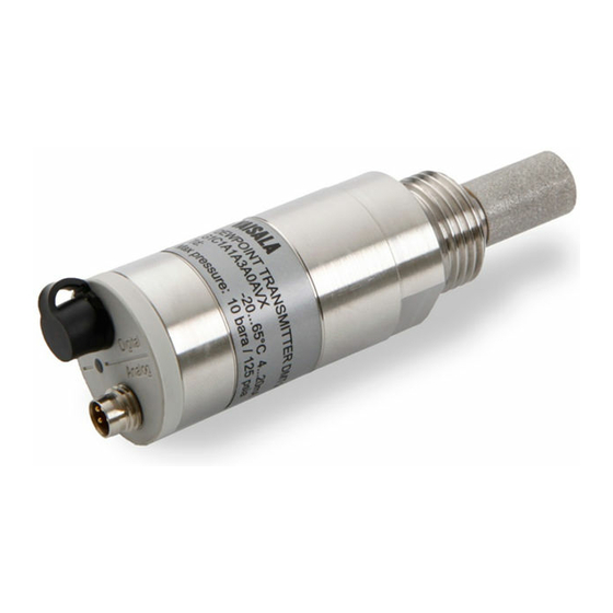
Vaisala DRYCAP® Dewpoint Transmitter DMT143 is a small and lightweight dewpoint transmitter
suitable for a wide range of OEM applications. DMT143 is easy to install and the mechanics have been
designed for harsh environments requiring protection against dust, dirt and splashed water.
There are two variants of the DMT143 transmitter, DMT143 and DMT143L.
DMT143 with DRYCAP® 180D sensor
•
either G1/2" ISO228/1 or NPT1/2" mechanical connection
•
measurement range -70 ... +60 °C (-94 ... +140 °F)
•
operating pressure up to 50 bara (725 psia)
•
voltage (V) or current (mA) analog output
DMT143L with DRYCAP® 180M sensor
•
G1/2" ISO228/1 mechanical connection
•
measurement range -70 ... + 60 °C° (-94 ... +140 °F)
•
operating pressure 0 ... 20 bara (0 ... 290 psia)
•
current (mA) analog output
DMT143L with DRYCAP® 180S sensor
•
G1/2" ISO228/1 mechanical connection
•
measurement range -50 ... + 60 °C° (-58 ... +140 °F)
•
operating pressure 0 ... 20 bara (0 ... 290 psia)
•
current (mA) analog output
Procedure Instruction
Field Tech Manual for DMT143-series
2018-04-06
Creator
Status Reason
JAMM
First revision
1(16)
Advertisement
Table of Contents

Related Manuals for Vaisala DMT143


Summary of Contents for Vaisala DMT143
-
Page 1: General Product Info
Vaisala DRYCAP® Dewpoint Transmitter DMT143 is a small and lightweight dewpoint transmitter suitable for a wide range of OEM applications. DMT143 is easy to install and the mechanics have been designed for harsh environments requiring protection against dust, dirt and splashed water. -
Page 2: Table Of Contents
2018-04-06 Vaisala Instruments Table of Contents General Product info ....................... 1 There are two variants of the DMT143 transmitter, DMT143 and DMT143L....1 Table of Contents ......................2 Service policy ........................3 Tools needed ........................3 Wiring ..........................4 Trouble Shooting ...................... -
Page 3: Service Policy
Accredited calibration is available for a new unit and the older ones too. Configuration of the calibration is defined to order form of a new unit Tools needed - Power supply (V 10...35V and I > 1A) - Standard PC terminal software - Vaisala USB service cable (order code 219690) - Multimeters (DVMs) -
Page 4: Wiring
Procedure Instruction 4(16) Field Tech Manual for DMT143-series 2018-04-06 Vaisala Instruments Wiring Property Description/Value Recommended calibration interval 2 years to confirm the specified accuracy Current Output Signal 4 … 20 mA. Operating voltage with current output 18 ... 28 VDC with voltage output 12 ... -
Page 5: Trouble Shooting
Procedure Instruction 5(16) Field Tech Manual for DMT143-series 2018-04-06 Vaisala Instruments Trouble Shooting 4.1 Analog Output or Display does not match expected value Step 1.) Check the label on transmitter, to verify the transmitter configuration of parameters, engineering units and scale for appropriate channel. -
Page 6: Checking Error Messages With Service Port
2018-04-06 Vaisala Instruments Second, your process may fluctuate greatly. Try adjusting Filtering on control device in an effort to stabilize readings. Or try adjusting FILT command with USB Service Cable for DMT143 output filtering response Set DMT143 Measurement Filtering Use the FILT command to view or set the speed at which the latest measurement result is integrated into the output readings. -
Page 7: Solving Typical Problems
If resetting does not help, and if the problem is related to transmitter software or settings, you can restore the factory configuration of the transmitter by issuing the FRESTORE command. If you are unable to solve your problem with the transmitter, contact Vaisala technical support. Table 2. -
Page 8: Checking Error Messages With Service Port
Procedure Instruction 8(16) Field Tech Manual for DMT143-series 2018-04-06 Vaisala Instruments 4.4 Checking Error Messages with Service Port If the transmitter has error messages, they can be read on the serial line using the ERRS command. Example (one active error, caused by physical damage to the sensor):... -
Page 9: Changing Output Parameter And Channel Information
= Parameter that is output on analog channel. Available parameters are TDF, TDFA, H2O. If the transmitter has been ordered from Vaisala with a relative humidity output on the analog channel, also parameter RH is available. lowlimit = Lower limit of parameter scaling. -
Page 10: Reset To Factory Ordered Configuration
Procedure Instruction 10(16) Field Tech Manual for DMT143-series 2018-04-06 Vaisala Instruments Example (show current settings): asel Ch1 Tdf lo : -80.00 'C ? Ch1 Tdf hi : 20.00 'C ? Example (change output parameter to H2O, set low and high limits): asel h2o 0 5000 Ch1 H2O lo : 0.00 ppm... -
Page 11: Maintenance
Procedure Instruction 11(16) Field Tech Manual for DMT143-series 2018-04-06 Vaisala Instruments Maintenance Visual Check This tasks should take into consideration at least following issues: - Surface (materials) - Oxidation, water leaking - Sensors - Cables (if any), cable heads - Connectors... -
Page 12: Spare Or Replacement Parts Available For Customers
Procedure Instruction 12(16) Field Tech Manual for DMT143-series 2018-04-06 Vaisala Instruments Spare or Replacement parts available for customers... -
Page 13: Calibration And Adjustment
- DMT143 to Port II 3. If you have altered the DMT143 serial port settings, switch off the other power supply (disconnect “Analog” cable if in use) before powering up the MI70. Note that this powers off the transmitter, and it will carry out the startup sequence (see section DMT143 Startup Sequence on page 20) when powered on again. - Page 14 Check the setting in the Settings - User Interface menu, and change if necessary. 7. The MI70 can display three parameters at one time. To compare the readings of the DMT143 and the reference probe, select the desired parameter from the Display – Quantities and Units menu of the MI70.
-
Page 15: Dmt143 Order Codes
Procedure Instruction 15(16) Field Tech Manual for DMT143-series 2018-04-06 Vaisala Instruments DMT143 Order Codes... -
Page 16: Calculate Ma And Process Values
Procedure Instruction 16(16) Field Tech Manual for DMT143-series 2018-04-06 Vaisala Instruments Calculate mA and Process Values To find the mA current value from Process Value: I = (Ihigh - Ilow)/(PVhigh - PVlow) x (PV - PVlow) + Ilow For example:...