Table of Contents
Advertisement
Quick Links
Advertisement
Table of Contents

Related Manuals for Teledyne Lecroy AP033


Summary of Contents for Teledyne Lecroy AP033
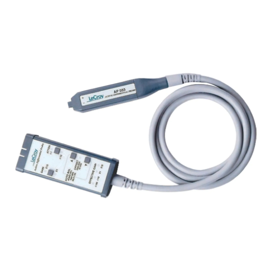
- Page 1 Operator’s Manual AP033 Active Differential Probe...
- Page 3 AP033 Active Differential Probe Operator’s Manual May 2013...
- Page 4 Spare parts, replacement parts and repairs are warranted for 90 days. In exercising its warranty, Teledyne LeCroy, at its option, will either repair or replace any assembly returned within its warranty period to the Customer Service Department or an authorized service center.
-
Page 5: Table Of Contents
Selecting the Proper Range .................. 11 Operation with Teledyne LeCroy Oscilloscopes ........... 12 Adding Offset......................14 Autobalance ......................15 Designing Test Fixtures for the AP033 Probe ............16 Maintenance ..................... 17 Cleaning ........................ 17 Calibration Interval ....................17 Service Strategy ....................17 Troubleshooting .................... - Page 6 AP033 Active Differential Probe Matching Procedure for ÷10 Plugs ..............22 Equipment Required .....................22 Procedure ......................23 Performance Verification ................... 25 Test Equipment Required ..................25 Preliminary Procedure ..................27 Procedure ......................27 Adjustment Procedure ..................35 Introduction ......................35 Test Equipment Required ..................36 Preliminary Procedure ..................38 Procedure ......................39...
-
Page 7: Safety Instructions
Operator’s Manual Safety Instructions This section contains instructions that must be observed to keep this oscilloscope accessory operating in a correct and safe condition. You are required to follow generally accepted safety procedures in addition to the precautions specified in this section. The overall safety of any system incorporating this accessory is the responsibility of the assembler of the system. -
Page 8: Operating Environment
AP033 Active Differential Probe Do not overload. To avoid electric shock, do not apply any potential that exceeds the maximum rating of the probe and/or the probe accessory, whichever is less. Observe all terminal ratings of the instrument before connecting the probe. -
Page 9: Overview
ProBus interface. Applications The AP033 is ideal for acquiring high speed differential signals such as those found in disk drive read channels, differential LAN, video, etc. It can also be used with spectrum analyzers to acquire signals in some RF systems (for example, balanced IF mixers in hand held cellular telephones). -
Page 10: Standard Accessories
8.1.0 or higher loaded; all X-Stream oscilloscopes are compatible. The software version installed in a Teledyne LeCroy oscilloscope can be verified by pressing the SHOW STATUS button on the front panel (where available), then selecting the System menu choice. The probe can be used with earlier versions of software;... -
Page 11: Specifications
Operator’s Manual Specifications Nominal Characteristics Nominal characteristics describe parameters and attributes that have are guaranteed by design, but do not have associated tolerances. Input Configuration: True Differential (+ and – Inputs); with shield Ground connector. Effective Gain X1, X10, ÷ ÷... - Page 12 AP033 Active Differential Probe Teledyne LeCroy measures CMRR with a fixture that connects the probe tip ground to the signal source ground. This method is necessary to obtain a reproducible CMRR measurement. Often, users leave the probe tip ungrounded when measuring high frequency signals. Not grounding the probe tip can actually improve CMRR by allowing some of the common mode signal to be impressed across the entire length of the probe cable instead of from probe tip to probe ground.
- Page 13 Operator’s Manual Figure 1, Typical CMRR Graphs General Characteristics Temperature: 0° to 50° C Operating -40° to 75° C Storage Input Connectors: Compatible with 0.025” (0.635 mm) square pins. 0.036” (0.91 mm) maximum diameter (for round pins) Power Requirements: Powered from oscilloscope through ProBus interface or with ADPPS power supply.
-
Page 14: Operation
(ESD). Keep in mind that this is an active probe, and it should be handled carefully to avoid damage. When using the AP033, you are advised to take precautions against potential instrument damage due to ESD. - Page 15 Operator’s Manual can greatly reduce this effect by using short interconnection leads, and twisting them together to minimize the loop area. High common mode rejection requires precise matching of the relative gain or attenuation in the + and – input signal paths. Mismatches in additional parasitic capacitance, inductance, delay, and a source impedance difference between the + and –...
-
Page 16: Probe Input Loading
Attaching any probe to a test circuit will add some loading. In most applications, the high impedance of the AP033 Active Differential Probe inputs imparts an insignificant load to the test circuit. However at very high frequencies, the capacitive reactance of the probe’s input capacitance may load the circuit enough to affect measurement accuracy. -
Page 17: Selecting The Proper Range
ADPPS power supply and the test instrument. Selecting the Proper Range The AP033 has two independent controls that set the common mode range and equivalent volts/division. The probe gain can be set to x1 or x10. The gain control (GAIN) only affects the differential mode range of the probe. -
Page 18: Operation With Teledyne Lecroy Oscilloscopes
Exceeding the common mode range may introduce distortion into the AP033 output. To reduce the possibility of errors caused by exceeding the common mode range, the probe monitors the input voltage. If the common mode range is exceeded when the ... - Page 19 attenuator installed). Some of the transitions in scale factor will ÷ result in a change of the attenuation in the AP033 probe. The common mode range, input capacitance, and noise level of the probe will change with the probe attenuator setting. For...
-
Page 20: Adding Offset
The internal ÷ attenuator cannot be selected when the external ÷10 attenuator is installed. Adding Offset The AP033 has true differential offset capability. This allows you to remove a DC bias voltage from the differential input signal while maintaining DC coupling. By using probe offset rather than the “position”... -
Page 21: Autobalance
Operator’s Manual Figure 4, Effect of Differential Offset When the AP033 is used with a Teledyne LeCroy oscilloscope equipped with a ProBus interface and software versions 7.6.0 to 8.0.0, the probe offset must be controlled through either the Probe Offset menu selection in the COUPLING screen, or the buttons on the probe body. The channel control does not change the probe offset and, therefore, should not be used. -
Page 22: Designing Test Fixtures For The Ap033 Probe
To facilitate use with custom test fixtures, the input receptacles of the AP033 probe are compatible with commercially available 0.025 in. (0.635 mm) square pins. The receptacles do not require a specific rotational alignment for the square pin. The dimensions listed below can be used as a layout guide for a test fixture circuit board. -
Page 23: Maintenance
Service Strategy The AP033 circuits utilize fine pitch surface mount devices; it is, therefore, impractical to attempt component-level repair in the field. Defective probes must be returned to a Teledyne LeCroy service facility for diagnosis and exchange. A defective probe under warranty will be replaced with a factory refurbished probe. -
Page 24: Troubleshooting
7. Is a ProBus Power Supply Overload error message displayed? If so, remove all other ProBus accessories from the oscilloscope. Is the message still displayed? If so, remove the AP033. Is the message still displayed? If so, the oscilloscope should be returned for service. - Page 25 Operator’s Manual B. Incorrect Frequency Response Possible causes are a defective probe or oscilloscope, poor connections, or poor grounding. 1. Verify that the BW limiting of the oscilloscope is off. 2. Connect the probe to another oscilloscope. If the probe now measures properly, the problem may be in the oscilloscope.
-
Page 26: Returning A Probe
5. Package the probe case in a cardboard shipping box with adequate padding to avoid damage in transit. 6. Mark the outside of the box with the shipping address given to you by the Teledyne LeCroy representative; be sure to add the following: ... -
Page 27: Available Accessories
Be very specific as to the reason for shipment. Duties may have to be paid on the value of the service. Available Accessories Teledyne LeCroy Description Part Number Accessory Kit, AP033 without AC Coupler PK033 and Attenuator AP03X-FLEX-LEAD Flex Lead 405400003... -
Page 28: Matching Procedure For ÷10 Plugs
AP033 Active Differential Probe Matching Procedure for ÷10 Plugs 10 Plug-on attenuator provided as a standard accessory with the AP033 is calibrated to match ÷ the specific probe it was shipped with. Individual probes will have small variations in parasitic capacitance within the input circuits. -
Page 29: Procedure
Insert the pin into a short length of rigid plastic tubing to serve as a handle. Procedure 1. Attach the AP033 to the test oscilloscope. If the test oscilloscope is not equipped with ProBus, use the ADPPS to provide power for the AP033. - Page 30 13. Set the signal generator frequency to about 50 Hz, and the output amplitude to about 10 V. 14. Set the test oscilloscope Volts/Div to 20 mV (for Teledyne LeCroy oscilloscopes with ProBus) or 2 mV/Div when using the ADPPS with an oscilloscope without scale factor correction; set the time scale to 2 ms/Div.
-
Page 31: Performance Verification
Operator’s Manual Performance Verification This procedure can be used to verify the warranted characteristics of the AP033 Active Differential Probe. You can do the performance verification without removing the instrument covers and exposing yourself to hazardous voltages. Adjustment should only be attempted if a parameter measured in the Performance Verification Procedure is outside of the specified limits. - Page 32 BNC female-to-banana plug Pomona 1269 NOTE: If a Teledyne LeCroy ProBus equipped oscilloscope is not available, you may use an alternate oscilloscope that meets the other minimum specifications listed, and the model ADPPS power supply, to perform the performance verification procedure. The input termination of the alternate oscilloscope must be set to 50 Ω...
-
Page 33: Preliminary Procedure
Connect the male end of the ProBus extension cable to Channel 1 of the oscilloscope. 2. Turn the oscilloscope on and allow at least a 30- minutes warm-up time for the AP033 and test equipment before performing the Verification Procedure. - Page 34 10. Carefully align the four pins that correspond to the Differential Drive No Termination portion of the AP03x- CF01 Calibration Fixture with the input receptacles in the AP033 probe head. Press the probe into the fixture to fully engage the pins.
- Page 35 CMRR. 1. Disconnect the ProBus Extension cable from the AP033 and the oscilloscope. Reconnect the AP033 directly to the Channel 1 input of the oscilloscope.
- Page 36 AP033 Active Differential Probe 2. Carefully move the AP033 probe head from the Differential Drive No Termination connector of the AP033/AP034 Calibration Fixture to the Differential Drive 50 Ohm Termination connector. Make sure that the probe is fully engaged in the fixture.
- Page 37 Operator’s Manual 14. Carefully move the AP033 probe head from the Differential Drive 50 Ohm Termination connector of the AP033/AP034 Calibration Fixture to the Common Mode Drive 50 Ohm Termination connector. Make sure the probe is fully engaged in the fixture.
- Page 38 AP033 Active Differential Probe C. Check Low Frequency CMRR NOTE: The attenuation of the AP033 Active Differential Probe below 10 MHz is so insignificant that the Differential Mode Gain can be assumed to be unity (1.0). Because greater amplitudes are required to measure the higher CMRR specifications at low frequencies, the Function Generator will be used in place of the leveled sine wave generator for the low frequency CMRR test.
- Page 39 18. Remove all cables and test fixtures from the AP033 probe. This concludes the Performance Verification of the AP033. Complete and file the results recorded in the AP033 Performance Verification Test Record as required by your quality procedures. Apply a suitable calibration label to the AP033 housing as required.
- Page 40 AP033 Active Differential Probe AP033 Model: Serial Number: Asset or Tracking Number: Date: Technician: CALIBRATION MODEL SERIAL NUMBER DUE DATE OSCILLOSCOPE DIGITAL MULTIMETER LEVELED SINE WAVE GENERATOR HF SINE WAVE GENERATOR FUNCTION GENERATOR The function generator provides stimulus for making relative measurements. The output amplitude of the generator is measured with the DMM or oscilloscope in the procedure.
-
Page 41: Adjustment Procedure
CAUTION: The adjustment procedure will require removal of the probe covers. These covers are part of the ESD protection system of the AP033 Active Differential Probe. To protect the probe, you should perform the entire procedure on a static dissipating work surface Wear an antistatic grounding wrist strap and follow standard static control procedures. -
Page 42: Test Equipment Required
AP033 Active Differential Probe Test Equipment Required The table on the next page lists the test equipment and accessories, or their equivalents, that are required for complete calibration. Specifications given for the test equipment are the minimum necessary for accurate calibration. All test equipment is assumed to be correctly calibrated and operating within the specifications listed. - Page 43 Johanson 4192 Low Capacitance Screwdriver NOTE: If a Teledyne LeCroy ProBus equipped oscilloscope is not available, you may perform the adjustment procedure with an alternate oscilloscope that meets the other Minimum Specifications, and the model ADPPS power supply. The input termination of the oscilloscope must be set at 50 Ω...
-
Page 44: Preliminary Procedure
4. Connect the AP033 Active Differential Probe output to the female end of the ProBus Extension Cable. Be careful to align the ProBus pins with the corresponding connector correctly. Connect the male end of the ProBus Extension Cable to Channel 1 of the oscilloscope. -
Page 45: Procedure
Procedure A. Adjust Preliminary Probe DC Balance (R36) 1. From the oscilloscope’s front panel, select channel 1. Set the AP033 Atten/Gain to Manual, the Probe Atten to /10, and the Probe Gain to X10. 2. If necessary, set the probe offset to 0.000 V. - Page 46 AP033 Active Differential Probe Figure 8, Probe Tip Adjustment Locations B. Adjust Coarse DC Balance (R226) 1. Remove the shorting plug from the Logic Board. 2. Change the channel 1 Probe Gain to X1. 3. Reinsert the shorting plug into the two holes near the end of the Logic Board.
- Page 47 6. Short the output BNC connector by reconnecting the cable to the SHORT connector on the AP033/AP034 Calibration Fixture. The SHORT connector is the only BNC connector on the AP033/AP034 Calibration Fixture that does not have corresponding input pins for the probe tip.
- Page 48 1 of the oscilloscope although there is no signal cable attached. 2. In the Channel 1 “COUPLING” menu, set AP033 Atten/Gain to Manual, Probe Atten to /10 and Probe Gain to X10. 3. Connect a BNC cable from the output of the Function Generator to the Channel 2 input of the oscilloscope.
- Page 49 Auto. Set the BWL to 20 or 25 MHz. Adjust the OFFSET to 0.0 mV. 2. Carefully move the AP033 probe tip from the Common Mode Drive No Termination position of the AP033/AP034 Calibration Fixture to the Differential Drive No Termination position. Press the probe into the fixture to fully engage the pins.
- Page 50 AP033 for the next step. F. Adjust GAIN (R322C) 1. Set the AP033 offset to 0.000 V by rotating the OFFSET knob in the CHANNEL section of the oscilloscope (or with the OFFSET knob linked to the “COUPLING” menu when using the older software versions).
- Page 51 1. Press the UTILITIES button, then select the CAL BNC Setup menu. Set the Mode to CAL signal, the Shape to Square, the Amplitude to 1 V into 1 M Ω, and the Frequency to 1 kHz. 2. On the Channel 1, set AP033 Attenuation/Gain to Manual, Probe Attenuation to /10, and Probe Gain to X10.
- Page 52 AP033 Active Differential Probe H. Adjust Final Attenuator CMRR (C18A) 1. Carefully move the AP033 probe head from the Differential Drive 50 Ohm Termination portion of the AP033/AP034 Calibration Fixture to the Common Mode Drive 50 Ohm Termination portion. 2. Remove the BNC cable from the Differential Drive 50 Ohm Termination connector of the AP033/AP034 Calibration Fixture.
- Page 53 2. Perform the Attenuator Matching Procedure listed on page 22. Apply calibration seals in accordance with your quality procedures. This concludes the Adjustment Procedure. Repeat the Performance Verification procedure to complete the calibration of the AP033. 922260-00 Rev A...
-
Page 54: Reference Information
AP033 Active Differential Probe Reference Information Differential Mode and Common Mode Differential probes amplify the voltage difference that appears between the + and – inputs. This voltage is referred to as the Differential Mode or Normal Mode voltage. The voltage component that is referenced to earth ground, and is identical on both inputs, is rejected by the amplifier. -
Page 55: Common Mode Rejection Ratio
Operator’s Manual Common Mode Rejection Ratio The ideal differential probe or differential amplifier would amplify only the differential mode voltage component and reject all of the common mode voltage component. Real differential probes and amplifiers are less than ideal, so a small portion of the common mode voltage component appears in the output. -
Page 56: Certifications
AP033 Active Differential Probe Certifications This section certifies the probe’s Electromagnetic Compatibility (EMC), Safety and Environmental compliance. EMC Compliance EC D - EMC ECLARATION OF ONFORMITY The probe meets intent of EC Directive 2004/108/EC for Electromagnetic Compatibility. Compliance was demonstrated to the following specifications as listed in the Official Journal of the European... -
Page 57: Safety Compliance
Operator’s Manual —EMC & N USTRALIA EALAND ECLARATION OF ONFORMITY The probe complies with the EMC provision of the Radio Communications Act per the following standards, in accordance with requirements imposed by Australian Communication and Media Authority (ACMA): CISPR 11:2003 Radiated and Conducted Emissions, Group 1, Class A, in accordance with EN61326- 1:2006 and EN61326-2-1:2006. -
Page 58: Environmental Compliance
The probe is subject to disposal and recycling regulations that vary by country and region. Many countries prohibit the disposal of waste electronic equipment in standard waste receptacles. For more information about proper disposal and recycling of your Teledyne LeCroy product, please visit teledynelecroy.com/recycle. ESTRICTION OF AZARDOUS... -
Page 59: Contact Teledyne Lecroy
Ph: 800-909-7112 / 408-653-1260 customersupport@teledynelecroy.com psgsupport@teledynelecroy.com European Headquarters Singapore, Oscillosocpes Teledyne LeCroy SA Teledyne LeCroy Singapore Pte Ltd. 4, Rue Moïse Marcinhes Blk 750C Chai Chee Road #02-08 Case postale 341 Technopark @ Chai Chee 1217 Meyrin 1 Singapore 469003... - Page 60 AP033 Active Differential Probe 922260-00 Rev A...
- Page 63 Mouser Electronics Authorized Distributor Click to View Pricing, Inventory, Delivery & Lifecycle Information: Teledyne LeCroy AP033-ATTN...