
Related Manuals for Vaisala HMT120


Summary of Contents for Vaisala HMT120
- Page 1 M211244EN-C User Guide â Vaisala HUMICAP Humidity and Temperature Transmitter Series HMT120...
- Page 2 Street address: Vanha Nurmijärventie 21, FI-01670 Vantaa, Finland Mailing address: P.O. Box 26, FI-00421 Helsinki, Finland Phone: +358 9 8949 1 Visit our Internet pages at www.vaisala.com. © Vaisala Oyj 2018 local rules and regulations No part of this manual may be...
-
Page 3: Table Of Contents
Version Information..................7 Related Manuals....................7 Documentation Conventions................7 Trademarks......................8 Patent Notice.....................8 Product Overview................... 9 Introduction to HMT120..................9 Accessories......................9 Fixed and Remote Probe Models..............9 Optional Display....................10 Interchangeable Probe................... 10 Constant Output Probe.................. 10 Transmitter Parts....................11 Safety........................ - Page 4 HMT120 User Guide M211244EN-C Maintenance....................48 Removing and Fastening Fixed Humidity Probe........48 Removing and Fastening Remote Humidity Probe........49 Testing Analog Outputs................50 Replacing the HUMICAPâ Sensor..............51 Calibration and Adjustment..............52 Calibration and Adjustment Overview ............52 Push-Button Calibration................53 6.2.1 Adjusting Humidity and Temperature with Push Buttons....53...
- Page 5 Table of Contents Index..........................83 Warranty........................85 Technical Support..................... 85 Recycling........................85...
- Page 6 Drilling Instructions..................19 Figure 9 Optional Probe Mounting Clamp..............20 Figure 10 Optional Probe Mounting Flange..............20 Figure 11 HMT120 Component Board................21 Figure 12 Isolated Current Loop Wiring............... 22 Figure 13 Removing the Humidity Probe (Fixed Probe Model)......48 Figure 14 Removing the Humidity Probe (Remote Probe Model)......49...
- Page 7 List of Tables List of Tables Table Document Versions.....................7 Table 2 Related Manuals....................7 Table 3 Applicable Patents....................8 Table 4 Wiring Table......................22 Table 5 Default Serial Interface Settings..............23 Table 6 List of Serial Commands................. 26 Table 7 ? Command......................27 Table 8 Calcs Command....................28 Table 9 Cdate Command....................
- Page 8 HMT120 User Guide M211244EN-C Table 45 Mechanical Specifications................73 Table 46 Spare Parts and Accessories................74 Table 47 Temperature Dependence for A, m, and Tn..........77 Table 48 Temperature Dependence for A, m, and Tn..........78 Table 49 Accuracy of Dewpoint Temperature °C............80 Table 50 Accuracy of Mixing Ratio g/kg (Ambient Pressure 1013 mbar)....
-
Page 9: About This Document
Chapter 1 – About This Document 1. About This Document 1.1 Version Information Table 1 Document Versions Document Code Date Description M211244EN-C January 2018 This version. Factory calibration uncertainty specification updated. Spare parts list updated. Document template updated, content structure revised. M211244EN-B June 2013 Previous version. -
Page 10: Trademarks
Lists tools needed to perform the task. Indicates that you need to take some notes during the task. 1.4 Trademarks Vaisalaâ and HUMICAPâ are registered trademarks of Vaisala Oyj. 1.5 Patent Notice This product is protected by the following patents and their corresponding national rights: Table 3 Applicable Patents... -
Page 11: Product Overview
Other quantities, such as dewpoint (T ) can be calculated from the basic RH and T values according to the device configuration. HMT120 is powered with a 10 ... 30 VDC external loop voltage (20 ... 30 VDC when R <500 ohms) and it outputs two analog current signals... -
Page 12: Optional Display
You have the following options when purchasing a new probe from Vaisala: • Order a new probe and keep your current one. • Order a new probe and return the old one to Vaisala (replacement probe). Only probes that have a compatible digital output (VDIGI mode) can be used with the transmitter. -
Page 13: Transmitter Parts
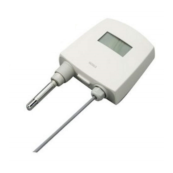
Chapter 2 – Product Overview 2.7 Transmitter Parts Figure 1 (page 11) shows the main transmitter parts. On the left is a remote probe model without display, and on the right is a fixed probe model with the optional display. Figure 1 Main Transmitter Parts Transmitter enclosure Probe cable HMP110 probe... -
Page 14: Safety
2.8.1 ESD Protection Electrostatic Discharge (ESD) can cause immediate or latent damage to electronic circuits. Vaisala products are adequately protected against ESD for their intended use. It is possible to damage the product, however, by delivering electrostatic discharges when touching, removing, or inserting any objects inside the equipment housing. -
Page 15: Installation
Chapter 3 – Installation 3. Installation 3.1 Opening the Transmitter Cover Figure 2 Opening the Transmitter Cover To open the transmitter cover: 1. If the transmitter is not mounted already, hold it against a flat surface. 2. Push on the cover with your thumb, and pull the bottom part of the cover towards yourself. -
Page 16: Wall Mounting
HMT120 User Guide M211244EN-C 3.2 Wall Mounting To mount the transmitter on a wall: 1. Remove the transmitter cover. 2. Make sure that the transmitter is correctly aligned and attach it directly to the wall with up to four screws (not included in the package). -
Page 17: Installation With Rain Shield
Chapter 3 – Installation 3.3 Installation with Rain Shield The installation kit with rain shield (Vaisala order code: 215109) includes a metal mounting plate and a rain shield for the transmitter. Figure 4 Installation with Rain Shield To install the transmitter with the rain shield: 1. -
Page 18: Installation With Radiation Shield
HMT120 User Guide M211244EN-C 3.4 Installation with Radiation Shield DTR504 with probe installation kit (Vaisala order code: DTR504A) includes the rain/ solar radiation shield DTR504 and a plastic installation support for the humidity probe. If you already have the DTR504 shield and... -
Page 19: Duct Installation Kit
Chapter 3 – Installation 3.5 Duct Installation Kit The duct installation kit includes a plastic pipe with a flange (Vaisala order code: 215619). To install the HMP110 probe with the duct installation kit, drill a hole to the duct wall, assemble the probe to the duct installation kit, slide the probe head through the hole, and attach the flange to the duct wall with four screws. -
Page 20: Probe Assembly With Duct Installation Kit
HMT120 User Guide M211244EN-C 3.5.1 Probe Assembly with Duct Installation Kit Figure 7 Probe Assembly with Duct Installation Kit HMP110 Duct installation kit Probe cable 1. Slide the probe cable through the duct installation kit plastic pipe. 2. Attach the probe cable to the HMP110 Humidity Probe. -
Page 21: Drilling Instructions For Duct Installation Kit
The optional mounting clamp makes it easy to install the probe on the wall of the measurement environment. The probe can be detached for calibration simply by loosening the lower screw. You can order a single clamp (Vaisala order code 225501) or a set of 10 clamps (226067). -
Page 22: Probe Mounting Flange
3.7 Probe Mounting Flange The probe mounting flange (Vaisala order code: 226061) is a general purpose mounting flange for 12 mm diameter probes. It can be used to hold the HMP110 probe in a through-wall installation. -
Page 23: Connections
Chapter 3 – Installation 3.8 Connections Figure 11 (page 21) shows the main parts of the HMT120 component board, including the wiring connectors. SHLD SERVICE PORT CH1- CH1+ CH2- CH2+ Figure 11 HMT120 Component Board Optional LCD display Indicator LEDs Adjustment buttons... -
Page 24: Wiring
HMT120 User Guide M211244EN-C 3.8.1 Wiring 1 SHLD 2 CH1- 10 ... 30 VDC 3 CH1+ 4 CH2- 10 ... 30 VDC 5 CH2+ Figure 12 Isolated Current Loop Wiring Table 4 Wiring Table Current Output (2-Wire, CH2 Isolated) Terminal Cable shield (optional) -
Page 25: Serial Line Operation
4.1 Using the Service Port The transmitter's motherboard has an 8-pin RJ-45 connector for service use. The service port uses RS-232 signaling levels. Vaisala offers an optional USB cable (Vaisala order code 219685) for connecting the transmitter to your computer. The service port is intended for short-term use such as calibration. For permanent installation, use the analog output. -
Page 26: Connecting With A Computer
3. Locate the cable in the list of devices: • If the device is listed as Vaisala USB Device with a COM port number in brackets, the cable is ready for use. Note the COM port number, you will need it later. - Page 27 The steps below describe how to connect to the transmitter using the PuTTY terminal application for Windows and a USB computer connection cable. 1. If you have not used the Vaisala USB cable before, install the driver before attempting to use the cable.
-
Page 28: List Of Serial Commands
HMT120 User Guide M211244EN-C 7. To open the connection window and start using the serial line, select Open. If PuTTY is unable to open the serial port you selected, it shows you an error message instead. If this happens, restart PuTTY and check the settings. -
Page 29: Device Information And Status
Chapter 4 – Serial Line Operation Command Description frestore Restore all transmitter settings to factory defaults help List available commands intv Set/show the continuous output interval Start continuous outputting reset Reset transmitter restore Restores the latest saved settings Stop continuous outputting save Save changed settings to FLASH memor send... -
Page 30: Table 8 Calcs Command
HMT120 User Guide M211244EN-C Syntax Description Example: Device Name : HMT120 SW Name : HMT120 SW model : HMT130 SW version : 0.9.3.389 Serial number : "F2220101" Address Unit : METRIC Ch1 Status : ON Ch2 Status : ON Probe name : "HMP110"... -
Page 31: Table 9 Cdate Command
Description ctext<cr> Show calibration information text. Calibration refers to the calibration of the transmitter's analog outputs. ctext [text]<cr> Set a new calibration information text to be shown after the automatic text "Calib. info". Example: ctext Calib. info: "VAISALA HELSINKI" >... -
Page 32: Table 11 Aout Command
HMT120 User Guide M211244EN-C Syntax Description Example (set a new information text): ctext Calibration lab 2 Calib. info: "Calibration lab 2" > Table 11 Aout Command Syntax Description aout<cr> The aout command shows the following information: • Analog out mode is the output mode for the channel, for example 0 ... -
Page 33: Table 12 System Command
: 12.37 mA > Table 12 System Command Syntax Description system<cr> Show probe firmware information. Example: system Device Name : HMT120 SW Name : HMT120 SW model : HMT120 SW version : 1.0.0.500 Serial number : A1234567 > Table 13 Vers Command... -
Page 34: Serial Line Output And Communication
HMT120 User Guide M211244EN-C Syntax Description Example: vers HMT120 / 0.1.0.103 4.7 Serial Line Output and Communication Table 14 R Command Syntax Description r<cr> Use the r command to start the continuous outputting of measurement values as an ASCII text string to the serial line. The output always includes the readings of the currently selected analog output quantities. -
Page 35: Table 16 Intv Command
Chapter 4 – Serial Line Operation Syntax Description Example: RH= 25.10% T= 24.77'C RH= 25.12% T= 24.96'C Table 16 Intv Command Syntax Description intv<cr> Use the intv command to show or set the output interval of the serial line measurement messages (applies when r command or RUN mode is used). -
Page 36: Calibration Commands
HMT120 User Guide M211244EN-C Syntax Description Example: send RH= 25.12 % T= 24.91 'C > 4.8 Calibration Commands Serial commands that are related to calibration are described in this section. For the actual calibration procedures, see Calibration and Adjustment Overview (page 52). -
Page 37: Table 19 Crhclr Command
Chapter 4 – Serial Line Operation Syntax Description Example 3: No calibration, only updating the value >crh 20.28000200 Ref1 ? 20.14000000 Ref1 ? Calibration terminated with ESC > Table 19 CRHCLR Command Syntax Description crhclr<cr> Use the crhclr command to restore the probe RH factory calibration. -
Page 38: Table 21 Ctclr Command
HMT120 User Guide M211244EN-C Syntax Description Example 2: 2-point calibration >ct 22.0007 Ref1 ? 22 Press ENTER to continue or ESC to exit 44.9847 Ref2 ? 45 > Example 3: No calibration, only updating the value >ct 22.0007 Ref1 ? 22.0145 Ref1 ? -
Page 39: Configuring Serial Line Operation
Chapter 4 – Serial Line Operation Syntax Description Example: >acal I1 (mA) ? 5.60 I2 (mA) ? 18.40 -1.40562890E+03 a0 1.41171900E+03 a1 I1 (mA) ? 5.60 I2 (mA) ? 18.40 -1.40562890E+03 a0 1.41171900E+03 a1 > The question mark is displayed after a certain stabilization time has expired. Only enter values after the question mark is displayed. -
Page 40: Table 24 Echo Command
HMT120 User Guide M211244EN-C Syntax Description Examples >seri Baud P D S : 19200 N 8 1 > >seri 9600 e 7 1 Baud rate : 9600 Parity Data bits Stop bits >save Saving settings...done > Table 24 ECHO Command Syntax Description echo [on] [off]<cr>... -
Page 41: Measurement Parameter Configuration Commands
>env Pressure (bar) : 1.013 > >env 0.980 Pressure (bar) : 0.98 >save Saving settings...done > You can use the Vaisala Humidity Calculator to simulate the effect of pressure change to dewpoint. The Humidity Calculator can be found at: www.vaisala.com/humiditycalculator... -
Page 42: Analog Output Configuration Commands
HMT120 User Guide M211244EN-C 4.11 Analog Output Configuration Commands Table 27 AERR Command Syntax Description aerr [level1 level2]<cr> Use the aerr command to show or set the analog output error levels. where level 1 level 2 Error levels for analog output channel Examples: >aerr... - Page 43 Chapter 4 – Serial Line Operation Syntax Description Examples: >asel Ch1 Quantity : RH RH lo RH hi : 100 Ch2 Quantity T lo : -60 T hi : 100 > >asel rh td Ch1 Quantity : RH RH lo RH hi : 100 Ch2 Quantity...
-
Page 44: Other Commands
HMT120 User Guide M211244EN-C Table 29 ATEST Command Syntax Description atest [val1 val2]<cr> Use the atest command to test the analog outputs. The atest command will force the where output to the given value, which can then be val1 val2 Analog channel output value (mA) measured with a calibrated multimeter. -
Page 45: Table 31 Form Command
Chapter 4 – Serial Line Operation Syntax Description Examples: >dsel 1. quantity : RH 2. quantity > >dsel rh t 1. quantity : RH 2. quantity > >dsel t 1. quantity > Table 31 FORM Command Syntax Description form <format><cr> After you have defined the quantities with the calcs command, use the form command to set where format is a formatting string that the output format for the send and r commands. -
Page 46: Table 32 Help Command
HMT120 User Guide M211244EN-C Syntax Description Examples: >form "RH= " 3.2 U2 rh #r #n >send RH= 32.16 % > >form "t=" 4.1 U3 t \t "rh=" 3.2 U2 rh \r \n >send 22.5 'C rh= 29.12 % > >form "t=" 4.1 U3 t \t "rh=" rh \r \n >send... -
Page 47: Table 34 Save Command
Chapter 4 – Serial Line Operation Syntax Description Example (no active errors): >errs No errors. > Table 34 SAVE Command Syntax Description save<cr> Use the save command to save changed settings to the transmitter FLASH memory. Most settings have to be saved or the changes are lost at the next reset or power down. -
Page 48: Table 36 Reset Command
HMT120 User Guide M211244EN-C Table 36 RESET Command Syntax Description reset<cr> Use the reset command to reset the transmitter. Upon reset or power-up, the transmitter enters the serial mode that has been set with the smode command. After a reset, the configuration is loaded from FLASH memory. - Page 49 Chapter 4 – Serial Line Operation Syntax Description Examples: >unit Unit : METRIC > >unit non_metric Unit : NON_METRIC >...
-
Page 50: Maintenance
HMT120 User Guide M211244EN-C 5. Maintenance 5.1 Removing and Fastening Fixed Humidity Probe To remove or replace the probe: 1. Loosen the metal locking bushing by carefully turning it counterclockwise. 2. Remove the probe from the transmitter by pulling it gently downwards. -
Page 51: Removing And Fastening Remote Humidity Probe
Chapter 5 – Maintenance 5.2 Removing and Fastening Remote Humidity Probe To remove or replace the probe: 1. Unscrew the small sleeve that secures the probe in place at the end of the probe cable and pull out the probe. 2. Replace the probe and screw the small sleeve back on, securing the probe tightly in place. Figure 14 Removing the Humidity Probe (Remote Probe Model) Probe cable Sleeve securing the probe to the cable... -
Page 52: Testing Analog Outputs
(4mA nominal). The output stays at this level for about 30 seconds after the - adjustment button has been pressed. HMT120 analog output current can be measured without removing the wires from the screw terminals by using a low-impedance multimeter between the... -
Page 53: Replacing The Humicapâ Sensor
Chapter 5 – Maintenance 5.4 Replacing the HUMICAP Sensor To replace the HUMICAPâ sensor on a fixed or remote probe: 1. Remove the filter (plastic grid or sintered stainless steel). 2. Remove the damaged sensor and insert a new one. 3. Recalibrate the probe. 4. -
Page 54: Calibration And Adjustment
• Portable humidity meters HM70 and HMI41 A calibrator kit is needed for calibration against saturated salt solutions. The HMK15 Humidity Calibrator and pre-measured certified salts are available from Vaisala. For further information, please contact your Vaisala representative. Vaisala Service Centers also offer accredited calibrations for humidity and temperature. -
Page 55: Push-Button Calibration
Chapter 6 – Calibration and Adjustment 6.2 Push-Button Calibration 485 TERM 485- SERVICE PORT 485+ Figure 16 Adjustment Buttons You can calibrate and adjust the transmitter with the adjustment buttons on the transmitter motherboard. The two-point humidity adjustment is carried out by using two relative humidity references: for example saturated salt points 11 % RH (LiCl) and 75 % RH (NaCl). - Page 56 HMT120 User Guide M211244EN-C 3. The transmitter is now in RH calibration state. Analog output and optional display will still follow the actual measured RH value. If you do not wish to perform the RH adjustment at this time, press the ADJ button one more time.
- Page 57 Chapter 6 – Calibration and Adjustment 8. Insert the probe into a known reference temperature (if Vaisala Humidity Calibrator HMK15 is not used) and let the temperature reading stabilize. Do not touch the adjustment buttons before the conditions have stabilized.
-
Page 58: Adjusting Rh And T With Mi70 Hand-Held Indicator
Indicator • MI70 hand-held indicator (included in, for example, the HM70 package) • MI70 connection cable (Vaisala order code: 211339) You can check and adjust the transmitter's relative humidity and temperature measurement with the MI70 (HM70) Hand-Held Humidity and Temperature meter. -
Page 59: Field Checking And Adjustment Using A Calibrated Reference Probe
Chapter 6 – Calibration and Adjustment 5. Press the ADJ button on the transmitter's motherboard to open the adjustment mode. Both LEDs on the motherboard remain in OFF state and the text "Starting adjustment mode for HMP110" is shown on the MI70 display. In transmitters with the optional display, the text MI70 adjustment mode is shown on the upper row of the display. -
Page 60: 1-Point Adjustment Using A Calibrator
HMT120 User Guide M211244EN-C 6.3.2 1-Point Adjustment Using a Calibrator Complete the steps listed in Adjusting RH and T with MI70 Hand-Held Indicator (page 56) before continuing with this adjustment option. 1. Remove the filter from the transmitter's probe and insert the probe head into the reference condition. -
Page 61: Licl-Nacl Adjustment
Chapter 6 – Calibration and Adjustment When making a 2-point adjustment, the difference between the two reference conditions must be at least 50 %RH. If the difference is < 50 %RH, the adjustment cannot be made. 1. Remove the filter from the transmitter's probe and insert the probe head into the lower reference condition. -
Page 62: Temperature Field Check And Adjustment Using A Calibrated Reference Probe
5. The adjustment is done. Press BACK and EXIT to return to the basic display. 6. Turn off the MI70 and detach the connection cable. 6.4 Adjustment with HMI41 You can check and adjust the transmitter's relative humidity measurement with the HMI41 indicator and HMP41/45/46 probes (requires the HMI41 connection cable (Vaisala order code: 25917ZZ)). -
Page 63: Figure 17 Location Of The Hmi41 Calibration Connector
Chapter 6 – Calibration and Adjustment Figure 17 Location of the HMI41 Calibration Connector HMI41 indicator 25917ZZ connection cable EXT connector There are three adjustment modes available: offset (dry point), gain (wet point), and 2-point adjustment. All of these can be performed using the HMI41 either as a reference meter (for example when the transmitter is mounted in an air-conditioning channel), or only as a terminal for visualizing and setting the transmitter's RH reading. -
Page 64: Connections And Selecting The Calibrator Function
HMT120 User Guide M211244EN-C 6.4.1 Connections and Selecting the Calibrator Function 1. To select the calibrator function from the HMI41, press the ON/OFF button until you can see some text on the display. Then release the ON/OFF button and within 1 ... 2 seconds,... -
Page 65: Adjusting Offset And Gain With Hmi41
Chapter 6 – Calibration and Adjustment 6. Press ON/OFF to finish. These setting are stored in the HMI41 memory; when the HMI41 is switched on again, it automatically starts up as a calibrator for digital transmitters with these serial line settings. After making these settings, continue with the adjustment and follow the directions of the chosen adjustment method. - Page 66 HMT120 User Guide M211244EN-C 5. Press ENTER to confirm the selection. A display similar to the following appears: If you are using a transmitter with the optional display, the message HMI41 adjustment mode is shown on the upper row of the display.
- Page 67 Chapter 6 – Calibration and Adjustment 2. Allow the readings to stabilize (can take 30 minutes or more). If you prefer, you can change the display to show the difference in the readings. Press HOLD and a display similar to the following appears: The numbers on the first line indicate how much the transmitter reading differs from that of the HMI41 reference probe.
- Page 68 HMT120 User Guide M211244EN-C 6.4.2.2 Adjustment Using HMI41 as Terminal Complete the steps (connect the cable and select adjustment mode) listed in Adjusting Offset and Gain with HMI41 (page 63) before continuing with this adjustment method. When you carry out an adjustment using HMI41 as a terminal, the HMI41 humidity probe is used for visualizing and setting the transmitter's RH reading manually.
-
Page 69: Troubleshooting Hmi41 Adjustment
Chapter 6 – Calibration and Adjustment 3. You can now set the blinking reading to the correct value (for example, the equilibrium RH of a salt solution) with the buttons. Press ENTER to complete the adjustment. If the adjustment has been successful, the following display appears: 4. - Page 70 HMT120 User Guide M211244EN-C Error Message Probable Cause Remedy This message can appear Wait. during adjustment when the HMI41 is trying to contact the transmitter. The connection cable is not Check the connection of the properly connected or the calibration cable. Check that...
-
Page 71: Troubleshooting
Chapter 7 – Troubleshooting 7. Troubleshooting 7.1 Error Codes The transmitter's software provides a variety of self diagnostics information, for example, FLASH and program memory checksum, probe communication status, probe checksum, operation voltage check, and oscillator fault check. At startup, the transmitter's software checks the factory/user settings checksum, program memory checksum, and oscillator fault status. -
Page 72: Solving Typical Problems
1. Reset or power cycle the module. Check if • Default settings checksum error the error disappears. 2. Return the module to factory settings with the frestore serial line command. Check again. 3. If the error is still active, contact a Vaisala service center. -
Page 73: Analog Output Error Notification
Chapter 7 – Troubleshooting Problem or Message Likely Causes and Solutions Any of the following errors is active: Faulty transmitter, contact a Vaisala service center. • Program checksum error • Factory flash defaults checksum error • Factory flash not initialized •... -
Page 74: Technical Data
HMT120 User Guide M211244EN-C 8. Technical Data 8.1 Specifications Table 42 Measurement Performance Property Description/Value Relative Humidity Measurement range 0 … 100 %RH Accuracy (including non-linearity, hysteresis, and repeatability) at 0 … +40 °C (+32 … +104 °F): 0 … 90 %RH ±1.5 %RH 90 …... -
Page 75: Table 43 Operating Environment
Chapter 8 – Technical Data Table 43 Operating Environment Property Description/Value Operating temperature of transmitter body, no -40 … +60 °C (-40 … 140 °F) display Operating temperature of transmitter body with -20 … +60 °C (-4 … 140 °F) display Operating temperature, HMP110 probe -40 …... -
Page 76: Spare Parts And Accessories
HMP110 probe for HMT120 HMP110 – separate order form HMP110R replacement probe for HMT120 HMP110R – separate order form HMP110T temperature only probe for HMT120 HMP110T – separate order form Constant output probe HMP110REF – separate order form Humidity sensor... -
Page 77: Transmitter Dimensions
Chapter 8 – Technical Data 8.3 Transmitter Dimensions Figure 18 Fixed Probe Model Dimensions in mm(in) -
Page 78: Figure 19 Remote Probe Model Dimensions In Mm(In)
HMT120 User Guide M211244EN-C Figure 19 Remote Probe Model Dimensions in mm(in) -
Page 79: Appendix A: Calculation Formulas
Appendix A – Calculation Formulas Appendix A. Calculation Formulas A.1 Calculation Formulas Overview The transmitter receives the relative humidity and temperature values from the HMP110 probe. Based on these temperature and relative humidity values, the transmitter calculates dewpoint, frostpoint, absolute humidity, mixing ratio, enthalpy, wet bulb temperature, saturation vapor pressure and vapor pressure in normal pressure. -
Page 80: Dew/Frostpoint Temperature Calculation
HMT120 User Guide M211244EN-C 50 ... 100 °C 5.9987 7.3313 229.10 100 ... 150 °C 5.8493 7.2756 225.00 150 ... °C 6.2301 7.3033 230.00 A.3 Dew/frostpoint Temperature Calculation Dew/frostpoint temperature (T ) is calculated with the following formula: � ≥ 0 �... -
Page 81: Saturation Vapor Pressure Calculation
Appendix A – Calculation Formulas A.5 Saturation Vapor Pressure Calculation Saturation vapor pressure (P ) is the equilibrium water vapor pressure in a closed chamber containing liquid water. It is a function only of temperature, and it indicates the maximum amount of water that can exist in the vapor state. Water vapor saturation pressure (P ) is calculated with the following 2 formulas: ∑... -
Page 82: Absolute Humidity Calculation
HMT120 User Guide M211244EN-C A.7 Absolute Humidity Calculation Absolute humidity (a) is defined as the mass of water vapour in a certain volume. If ideal gas behaviour is assumed, the absolute humidity can be calculated using the following formula: � �... -
Page 83: Accuracy Of Mixing Ratio G/Kg (Ambient Pressure 1013 Mbar)
Appendix A – Calculation Formulas Relative Humidity (%RH) Temp 160 °C 5.80 3.18 2.30 1.85 1.57 1.38 1.24 1.14 1.06 0.99 A.9.2 Accuracy of Mixing Ratio g/kg (Ambient Pressure 1013 mbar) Table 50 Accuracy of Mixing Ratio g/kg (Ambient Pressure 1013 mbar) Relative Humidity (%RH) Temp -40 °C... -
Page 84: Accuracy Of Absolute Humidity G/M
HMT120 User Guide M211244EN-C Relative Humidity (%RH) Temp 100 °C 3.06 2.04 1.58 1.31 1.14 1.01 0.92 0.85 0.80 0.75 120 °C 3.85 2.40 1.81 1.48 1.28 1.13 1.03 0.95 0.88 0.83 140 °C 4.57 2.73 2.03 1.65 1.41 1.25 1.13... -
Page 85: Index
HMI41 fixed and remote probe models..9 adjusting RH with MI70 hand-held indicator..........56 HMT120 component board....21 adjustment using HMI41 as reference HMT120 overview........9 meter............64 adjustment using HMI41 as terminal installing with radiation shield....16 adjustment with HM41...... - Page 86 HMT120 User Guide M211244EN-C MI70 adjustment: field checking and specifications..........72 adjustment using a calibrated reference probe........57 trademarks...........8 MI70 adjustment: LiCl- NaCl transmitter dimensions......75 adjustment..........59 transmitter parts........11 MI70 adjustment: temperature field troubleshooting HMI41 adjustment..67 check and adjustment using a calibrated reference probe....
-
Page 87: Warranty
Please see the applicable supply contract or Conditions of Sale for details of the warranty for each product. Technical Support Contact Vaisala technical support at helpdesk@vaisala.com. Provide at least the following supporting information: • Product name, model, and serial number •... - Page 88 HMT120 User Guide M211244EN-C...
- Page 90 www. v aisala.com...