Table of Contents
Advertisement
Advertisement
Table of Contents

Related Manuals for Strongway 55830

Summary of Contents for Strongway 55830
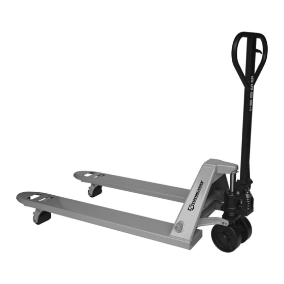
- Page 1 5500-Lb. Capacity Pallet Jack Owner’s Manual WARNING: Read carefully and understand all ASSEMBLY AND OPERATION INSTRUCTIONS before operating. Failure to follow the safety rules and other basic safety precautions may result in serious personal injury. Item #55830 READ & SAVE THESE INSTRUCTIONS...
- Page 2 Thank you very much for choosing a Strongway™ product! For future reference, please complete the owner’s record below: Serial Number/Lot Date Code: ________________________________ Purchase Date: ____________________________________________ Save the receipt, warranty, and this manual. It is important that you read the entire manual to become familiar with this product before you begin using it.
-
Page 3: Table Of Contents
Table of Contents Intended Use ............................4 Packaging Contents ..........................4 Technical Specifications ........................4 Important Safety Information ....................... 4 Specific Operation Warnings ....................... 5 Assembly Instructions .......................... 6 Operating Instructions .......................... 8 Maintenance ............................9 Troubleshooting ..........................11 Parts Diagram ............................12 Parts List .............................. -
Page 4: Intended Use
Intended Use The Strongway 5500 Lb. Capacity Pallet Jack is designed for transportation of loads with a level, attached base and may be used only on a firm and even surface, such as concrete or asphalt. The load must be on evenly distributed pallets, with the ideal loading mode such that the center of gravity of the load is at the central position of the fork. -
Page 5: Specific Operation Warnings
⚠WARNING WORK AREA SAFETY Inspect the work area before each use. Keep work area clean, dry, free of clutter, and well-lit. Cluttered, wet, or dark work areas can result in injury. Using the product in confined work areas may put you dangerously close to cutting tools and rotating parts. ... -
Page 6: Assembly Instructions
Be sure the load is secure and stable before moving. Do not operate a loaded pallet jack on ramps or inclines. Keep the load centered on the pallet jack. Wear steel toed boots while operating the pallet jack. ... - Page 7 1. Put the base of the HANDLE TUBE (Fig. 1) on the PRESSURE FRAME (Fig. 1). Align the holes (Fig. 1) at the base of the HANDLE with the holes in the PRESSURE FRAME. The chain should drop through the middle hole of SHAFT (Fig. 2). (Fig.
-
Page 8: Operating Instructions
Operating Instructions ⚠WARNING To avoid serious bodily injury or death, and/or property damage, do not exceed the rated load capacity. When not in use, do not allow heavy loads to remain on the fork for an extended period of time. Always lower the fork completely when not in use. -
Page 9: Maintenance
Note: These three positions have been set at the factory to work appropriately as soon as the handle tube is attached. Check to see if the pallet jack works well in the 3 control positions. If the forks do not raise or lower as expected, proceed to the following steps (see Fig. 4): 1. - Page 10 Maintenance Interval Maintenance Point 0.26L Fig. 5 LUBRICATION. Wheel bearings are sealed and require no lubrication. The crankshaft features “oil lite” bushings that also require no lubrication. Lightly oil all other moving parts. BLEEDING THE AIR. There may be times when the forks do not rise while pumping when in the LIFT position.
-
Page 11: Troubleshooting
Troubleshooting Failure Possible Cause Corrective Action See Bleeding the Air. Air in pump. Hydraulic unit does not lift Replace O-ring. Refer to Seal and O- Worn O-ring in ram cylinder. Ring Replacement. Deformed piston rod. Replace piston rod and cylinder. Lubricate/ replace rod. -
Page 12: Parts Diagram
Parts Diagram Parts List Reference Part Number Part Description Quantity Handle Tube Blade Spring Spring Elastic Pin Control Lever Roller Elastic Pin Elastic Pin Pull Rod Chain Adjusting Screw Screw Spring Washer Pressure Frame Shaft Shaft Oil Lite Bushing Pressure Roller Page 12 of 16... - Page 13 Reference Part Number Part Description Quantity Elastic Pin Release Plug O-Ring Release Screw Spring Valve Steel Ball Oil Baffle Washer O-Ring Valve Base Tapered Column Spring Washer Release Plug U-Packing Dust Seal Ring Spring Spring Cap E-Ring Plunger Piston Steel Ball Ram Piston Dust Seal Ring O-Ring...
-
Page 14: Replacement Parts
Reference Part Number Part Description Quantity Oil Lite Bushing Spring Pin Oil Lite Bushing Crank Pin Push Rod Crank Shaft Spring Pin Socket Head Cap Screw Fork Frame V Nut Guide Roller Hex Cap Screw Spring Pin Rod Pin Load Wheel Axle Flat Washer Ball Bearing Load Wheel... -
Page 15: Limited Warranty
Northern Tool and Equipment Company, Inc. ("We'' or ''Us'') warrants to the original purchaser only (''You'' or ''Your'') that the Strongway product purchased will be free from material defects in both materials and workmanship, normal wear and tear excepted, for a period of one year from date of purchase. - Page 16 Distributed by: Northern Tool & Equipment Company, Inc. Burnsville, Minnesota 55306 www.northerntool.com Made in China Page 16 of 16...