
Related Manuals for SolarEdge SE7600A-US


Summary of Contents for SolarEdge SE7600A-US
- Page 1 SolarEdge StorEdge Solution with Backup Installation Guide For North America Version 1.3...
-
Page 2: Revision History
450V DC to BAT connector (DC- and DC+ connections) corrected in the connection diagram Added a diagram of LG battery connection to inverter with 3 DIP switches In Configuration Menu Options: Power Control section: Removed Phase Balance link and info Added a note about compliance with UL 1741 Supplement A. Added link to P(Q) diagram application note Maintenance section: Added links to application notes (Upgrading the inverter using SD card; Isolation fault troubleshooting; Arc fault detection) Removed Optimizer Conf In System Configuration chapter: The communication board firmware (CPU) version must be 3.xxxx and later on all SolarEdge inverters at the same site Screens changed when configuring LG battery StorEdge Control instructions and menu updated Connection Unit replacement - removed Updated links Technical specification - updated SolarEdge-StorEdge Installation Guide MAN-01-00262-1.3... -
Page 3: Disclaimers
The material furnished in this document is believed to be accurate and reliable. However, SolarEdge assumes no responsibility for the use of this material. SolarEdge reserves the right to make changes to the material at any time and without notice. You may refer to the SolarEdge web site (http://www.solaredge.us) for the most updated version. All company and brand products and service names are trademarks or registered trademarks of their respective holders. Patent marking notice: see h ttp://www.solaredge.us/patent The general terms and conditions of delivery of SolarEdge shall apply. The content of these documents is continually reviewed and amended, where necessary. However, discrepancies cannot be excluded. No guarantee is made for the completeness of these documents. The images contained in this document are for illustrative purposes only and may vary depending on product models. FCC Compliance This equipment has been tested and found to comply with the limits for a Class B digital device, pursuant to part 15 of the FCC Rules. These limits are designed to provide reasonable protection against harmful interference in a residential installation. This equipment generates, uses and can radiate radio frequency energy and, if not installed and used in accordance with the instructions, may cause harmful interference to radio communications. However, there is no guarantee that interference will not occur in a particular installation. If this equipment does cause harmful interference to radio or television reception, which can be determined by turning the equipment off and on, you are encouraged to try to correct the interference by one or more of the following measures: Reorient or relocate the receiving antenna. Increase the separation between the equipment and the receiver. Connect the equipment into an outlet on a circuit different from that to which the receiver is connected. Consult the dealer or an experienced radio/TV technician for help. Changes or modifications not expressly approved by the party responsible for compliance may void the user’s authority to operate the equipment. SolarEdge-StorEdge Installation Guide MAN-01-00262-1.3... -
Page 4: Table Of Contents
Inverter Package Contents Identifying the Inverter Inverter Interfaces Connection Unit Internal AC Breaker and Bypass Switch Mounting the Inverter Chapter 4: Auto-transformer and Backed-up Loads Panel Installation (for Backup) Mounting the Auto-transformer Installing the Backed-up Loads Panel Chapter 5: Meter Installation Chapter 6: StorEdge Inverter Connections Installing the 9V Battery and Fuses Connecting the Strings to the Inverter Connecting to the Battery DIP Switch Setup DIP Switch Setup in Meter and Inverter DIP Switch Setup in the Connection Unit Connecting Communication to the Meter Connecting to AC Connecting to the Auto-transformer SolarEdge-StorEdge Installation Guide MAN-01-00262-1.3... - Page 5 Language Communication Power Control Display Maintenance Information Status Screens - Operational Mode Initial S tatus Main Inverter Status Energy Meter Status Telemetry Status ID Status Server Communication Status IP Status ZigBee Status Cellular Status GSM Status Communication Ports Status Smart Energy Management Status Power Control Status Battery Status Charge/ Discharge Profile Programming Status Chapter 9: Setting Up Communication to the Monitoring Platform Communication Options Ethernet RS485 SolarEdge-StorEdge Installation Guide MAN-01-00262-1.3...
- Page 6 Appendix B: Opening Conduit Drill Guides Appendix C: Replacing and Adding System Components Replacing an Inverter 9V Battery Replacement Fuse Replacement Battery Replacement Appendix D: Mechanical Specifications Inverter Dimensions Auto-transformer Dimensions StorEdge Single Phase Inverter with Connection Unit for High Power - Technical Specifications StorEdge Inverter Auto-Transformer Technical Specifications SolarEdge-StorEdge Installation Guide MAN-01-00262-1.3...
-
Page 7: Handling And Safety Instructions
Denotes a hazard. It calls attention to a procedure that, if not correctly performed or adhered to, could result in damage or destruction of the product. Do not proceed beyond a caution sign until the indicated conditions are fully understood and met. NOTE Denotes additional information about the current subject. IMPORTANT SAFETY FEATURE Denotes information about safety issues. SolarEdge-StorEdge Installation Guide MAN-01-00262-1.3... -
Page 8: Important Inverter Safety Instructions
Code Electrique Canadien, Partie 1, pour les installations faites au Canada). La mise à la terre des équipements est la responsabilité de l’installateur et doit être faite en accord avec les toutes les règles locales et nationales applicables. SolarEdge-StorEdge Installation Guide MAN-01-00262-1.3... - Page 9 NOTE A SolarEdge inverter may be installed in a site with a generator, however must not operate at the same time as the generator. Operating an inverter and a generator simultaneously will void the warranty. SolarEdge requires installing a physical or electronic interlock, which will prevent the generator and inverter from operating simultaneously.
- Page 10 The battery used must be NRTL certified. NOTE For battery decommissioning and disposal, follow the manufacturer requirements and instructions. NOTE The Connection Unit is NEMA type 3R rated . Unused conduit openings and glands should be sealed with appropriate seals. SolarEdge-StorEdge Installation Guide MAN-01-00262-1.3...
-
Page 11: Chapter 1: Overview
f unctionality as a DC-optimized P V inverter. SolarEdge offers a StorEdge the following inverter types: StorEdge inverter for Single Battery or High Capacity StorEdge inverter for High Power. The Connection Unit, located at the bottom of the inverter, allows simple installation and connectivity to other system components and includes a DC Safety Switch. The SolarEdge Electricity Meter - The meter is used by the inverter for export/ consumption readings, and for S mart Energy Management applications, such as: export limitation, time-of-use profile programming and maximizing self-consumption. The meter is required only in systems using Smart Energy Management applications (it is not required for StorEdge systems used only for backup power). The Auto-transformer - The auto-transformer handles the phase load balancing. It is required only in systems providing backup power. One battery - d esigned to work with the SolarEdge StorEdge system. Figure 1: StorEdge system components SolarEdge-StorEdge Installation Guide MAN-01-00262-1.3... - Page 12 ü Battery NOTE Additional SolarEdge inverters (without batteries) can be connected with RS485. The inverters will participate in export limitation and Smart Energy Management. Connecting multiple inverters with RS485 master-slave connection may require an RS485 Expansion Kit (available from SolarEdge).
-
Page 13: Installation Workflow
Power optimizers - as described in Installing the Power Optimizers on page 13. Inverter - as described in Installing the Inverter on page 20. Step 2 - SolarEdge Auto-transformer and AC load panel installation (required for Backup Power only): Refer to Auto-transformer and Backed-up Loads Panel Installation (for Backup) on page 27. Step 3 - Electricity Meter installation (required for Smart Energy Management only). Refer to Meter Installation on page 29. Step 4 - Connecting PV strings (DC) to the inverter - Refer to Connecting the Strings to the Inverter on ... -
Page 14: Installation Equipment List
Appropriate mounting hardware ( for example: stainless bolts, nuts, and washers) for attaching: the mounting bracket to the mounting surface the power optimizer to the racking (not required for smart modules) Wire cutters Wire strippers Voltmeter For installing the communication options, you may also need the following: For Ethernet: CAT5/6 twisted pair Ethernet cable with RJ45 connector. If using a CAT5/6 cable spool: RJ45 plug and RJ45 crimper For RS485: Four- or six-wire shielded twisted pair cable. Watchmaker precision screwdriver set Inverter Transport and Storage Transport the inverter in its original packaging, facing up and without exposing it to unnecessary shocks. If the original package is no longer available, use a similar box that can withstand the weight of the inverter (refer to the inverter weight in the specification datasheet provided with the unit), has a handle system and can be closed fully. Store the inverter in a dry place where ambient temperatures are -13°F - 140°F / -25°C - +60°C . SolarEdge-StorEdge Installation Guide MAN-01-00262-1.3... -
Page 15: Chapter 2: Installing The Power Optimizers
Pour installation à même le module ou la monture du module, consultez d'abord le fabricant du module sur la position et son impact sur la garantie du module. Le perçage de trous dans le cadre du module devra se faire suivant les instructions du fabricant. SolarEdge-StorEdge Installation Guide MAN-01-00262-1.3... -
Page 16: Package Contents
IMPORTANT SAFETY FEATURE Modules with SolarEdge power optimizers are safe. They carry only a low safety voltage before the inverter is turned ON. As long as the power optimizers are not connected to the inverter or the inverter is turned OFF, each power optimizer will output a safe voltage of 1V. -
Page 17: Step 1: Mounting And Grounding The Power Optimizers
2 These methods have been evaluated by a nationally recognized testing laboratory as part of the optimizer evaluation. The SolarEdge-supplied grounding lug kit has been evaluated only for use with SolarEdge power optimizers. It is not intended or listed to be used as a general purpose grounding lug with other electrical equipment. - Page 18 For mounting on rails with sliding nut fasteners: If the star washer cannot be used, use the SolarEdge grounding plate (purchased separately) between the railing and the flat side of the mounting bracket. Use mounting specific hardware as needed. Apply torque of 9.5 N*m / 7 lb*ft. See Figure 3 Figure 3: Power optimizer installation and grounding using a grounding plate For mounting on un-grounded structures (such as a wooden structure): If the star washer or the plate cannot be used, use the SolarEdge grounding lug (purchased separately) with an equipment-grounding conductor a ccording to the supplied instructions. The grounding terminal accepts a wire size of 6-14 AWG, and must be sized for equipment grounding per NEC 250.122 requirements. Tighten the screws connecting the power optimizer to the frame and the grounding terminal screw. Apply torque of 9.5 N*m / 7 lb*ft. See Figure 4 SolarEdge-StorEdge Installation Guide MAN-01-00262-1.3...
-
Page 19: Step 2: Connecting A Pv Module To A Power Optimizer
NOTE Images are for illustration purposes only. Refer to the label on the product to identify the plus and minus input and output connectors. For each of the power optimizers: Connect the Plus (+) output connector of the module to the Plus (+) input connector of the power optimizer. Connect the Minus (-) output connector of the module to the Minus (-) input connector of the power optimizer. Figure 5: Power optimizer connectors SolarEdge-StorEdge Installation Guide MAN-01-00262-1.3... -
Page 20: Step 3: Connecting Power Optimizers In Strings
Input and output connectors are not watertight until mated. Open connectors should be mated to each other or plugged with appropriate watertight caps. Les connecteurs d’entrée et sortie ne sont pas étanches jusqu'à ce qu’ils soient accouplés. Les connecteurs doivent être accouplés ou fermés avec des terminaux étanches. SolarEdge-StorEdge Installation Guide MAN-01-00262-1.3... -
Page 21: Step 4: Verifying Proper Power Optimizer Connection
When a module is connected to a power optimizer, the power optimizer outputs a safe voltage of 1V. Therefore, the total string voltage should equal 1V times the number of power optimizers connected in series in the string. For example, if 10 power optimizers are connected in a string, then 10V should be produced. Make sure the PV modules are exposed to sunlight during this process. The power optimizer will only t urn ON if t he PV module provides at least 2W. In SolarEdge systems, due to the introduction of power optimizers between the PV modules and the inverter, the short circuit current I and the open circuit voltage V hold different meanings from those in traditional systems. For more information about the SolarEdge s ystem’s string voltage and current, refer to the V and I in SolarEdge Systems Technical Note, available on the SolarEdge website at: http://www.solaredge.us/files/pdfs/isc_and_voc_in_solaredge_systems_technical_ note.pdf. To verify proper power optimizers connection: Measure the voltage of each string individually before connecting it to the other strings or to the inverter. Verify correct polarity by measuring the string polarity with a voltmeter. Use a voltmeter with at least 0.1V measurement accuracy. For troubleshooting power optimizer operation problems, refer to Power Optimizer Troubleshooting on page 96. SolarEdge-StorEdge Installation Guide MAN-01-00262-1.3... -
Page 22: Chapter 3: Installing The Inverter
Chapter 3: Installing the Inverter Install the inverter either before or after the modules and power optimizers have been installed. Inverter Package Contents One StorEdge inverter One mounting bracket Two Allen screws for fastening the inverter to the mounting bracket SolarEdge activation card One 9V battery Allen key f or opening the Connection Unit Installation guide (with activation card and instructions) Identifying the Inverter Refer to the sticker on the inverter t hat specifies its Serial Number and its Electrical Ratings. P rovide the serial number when contacting SolarEdge support. The serial number is also required when opening a new site in the SolarEdge monitoring platform. SolarEdge-StorEdge Installation Guide MAN-01-00262-1.3... -
Page 23: Inverter Interfaces
Monitoring information is being received from a power Yellow inverter shutdown optimizer. The inverter is being shut down. On - There is an error. Refer to Troubleshooting on page 93 for Fault more information. Blinking - The inverter is being shut down. All LEDs turn on while the inverter is being configured. SolarEdge-StorEdge Installation Guide MAN-01-00262-1.3... -
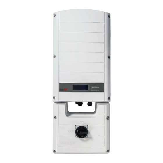
Page 24: Connection Unit
Connection Unit Figure 8: Inverter front view Connection Unit Figure 9: Connection Unit The Connection Unit i ncludes: DC safety switch: disconnects both the positive and negative conductors of the PV and the positive and negative conductors of the battery. Openings for conduit entry: Four openings are ready to use and have sealing covers. Two openings are closed with drill guides. If required, open the drill guides as described in Opening Conduit Drill Guides on page 102. SolarEdge-StorEdge Installation Guide MAN-01-00262-1.3... -
Page 25: Internal Ac Breaker And Bypass Switch
Mounting the Inverter The inverter is supplied with a mounting bracket. Figure 11: Mounting bracket NOTE Make sure the mounting surface or structure can support the weight of the inverter and bracket, and make sure that it spans the width of the bracket. SolarEdge-StorEdge Installation Guide MAN-01-00262-1.3... - Page 26 Depending on the angle, use the appropriate size and number of spacers so that the bracket is perpendicular to the ground. Recommended: a stainless steel 3/4" long screw, with a 1/4" socket button head , two jam nuts and three washers. 4. Hang the inverter on the bracket (see Figure 12): Lift the inverter from the sides, or hold it at the top and bottom of the inverter to lift the unit into place. Do not lift holding the Connection Unit as it may be damaged. SolarEdge-StorEdge Installation Guide MAN-01-00262-1.3...
- Page 27 Chapter 3: Installing the Inverter 5. Align the two indentations in the inverter enclosure with the two triangular mounting tabs of the bracket, and lower the inverter until it rests on the bracket evenly. Figure 12: Hanging the inverter on the bracket 6. Secure the Connection Unit bracket to the wall: Mark the location of the bracket screw for the Connection Unit and drill the hole. Fasten the bracket using a standard bolt. Verify that the bracket is firmly attached to the mounting surface. Figure 13: Connection Unit bracket 7. Insert the two supplied screws through the outer heat sink fin on both sides of the inverter and into the bracket (see Figure 12). Tighten the screws with a torque of 4.0 N*m / 2.9 lb.*ft. 8. Remove the inverter cover: Open the inverter cover’s six Allen screws and carefully pull the cover horizontally before lowering it. SolarEdge-StorEdge Installation Guide MAN-01-00262-1.3...
- Page 28 Mounting the Inverter 9. Remove the Connection Unit covers: a. Release the six screws attaching the Connection Unit external cover to the enclosure and lift the cover. b. Open the four internal screws securing the transparent cover to the e nclosure and remove the cover. Figure 14: Inverter Covers SolarEdge-StorEdge Installation Guide MAN-01-00262-1.3...
-
Page 29: Chapter 4: Auto-Transformer And Backed-Up Loads Panel Installation (For Backup)
Chapter 4: Auto-transformer and Backed-up Loads Panel Installation (for Backup) Chapter 4: Auto-transformer and Backed-up Loads Panel Installation (for Backup) The auto-transformer is used for backup power only, and is not mandatory if using Smart Energy Management applications only. Refer to the table on page 10. The auto-transformer connects to the AC side of the inverter. Since the inverter AC connections are on its right side, it is recommended to position the auto-transformer to the right of the inverter to simplify wiring. SolarEdge-StorEdge Installation Guide MAN-01-00262-1.3... -
Page 30: Mounting The Auto-Transformer
2. Install the bracket with the flat side facing down. Verify that the bracket is firmly attached to the mounting surface. 3. Hang the auto-transformer on the bracket: Lift the a uto-transformer from the sides, or hold it at the top and bottom to lift the unit into place. 4. Insert the two supplied screws through the outer heat sink fin on both sides of the auto-transformer and into the bracket. Tighten the screws with a torque of 4.0 N*m / 2.9 lb.*ft. Figure 15: Installing the auto-transformer Installing the Backed-up Loads Panel Install a secondary AC panel for backed-up loads (not supplied by SolarEdge). Rewire the backed-up loads through this panel. Install two poles 25A main circuit breaker o n this panel, to ensure the 25A phase imbalance limit is maintained at all times. Install a residual-current device (RCD) in accordance with the applicable local standards and directives Figure 16: Backed-up Loads Panel SolarEdge-StorEdge Installation Guide MAN-01-00262-1.3... -
Page 31: Chapter 5: Meter Installation
Wire cross-section area: 0.2-1 mm²/ 24-18 AWG (a CAT5 cable may be used) NOTE The inverter RS485 bus should be connected to the battery and meter. Connecting multiple inverters with RS485 master-slave connection may require an RS485 Expansion Kit (available form SolarEdge; Refer to http://www.solaredge.com/files/pdfs/RS485_expansion_kit_installation_ guide.pdf). For communication connection refer to Connecting Communication to the Meter on page 40. SolarEdge-StorEdge Installation Guide MAN-01-00262-1.3... -
Page 32: Chapter 6: Storedge Inverter Connections
The conduits, hubs and fittings must be suited for field wiring systems. The hubs and other fittings must comply with UL514B. Use the conduit and wiring appropriate for the installation location per the NEC. Outdoor installations must use components that are rated NEMA 3R or higher. SolarEdge-StorEdge Installation Guide MAN-01-00262-1.3... - Page 33 Chapter 6: StorEdge Inverter Connections The following figure shows the connections in the Connection Unit: Figure 17: The Connection Unit connections SolarEdge-StorEdge Installation Guide MAN-01-00262-1.3...
-
Page 34: Installing The 9V Battery And Fuses
Installing the 9V Battery and Fuses Installing the 9V Battery and Fuses A 9V battery is supplied with the inverter accessories. Install the 9V battery in the holder on the top board of the Connection Unit and connect it to the battery pad. Figure 18: The battery holder Two 25A fuses are supplied with the high power inverters. Install the fuses in the holders on the top board of the Connection Unit . Figure 19: Connection Unit fuses SolarEdge-StorEdge Installation Guide MAN-01-00262-1.3... -
Page 35: Connecting The Strings To The Inverter
For systems with four PV strings or more, fuses may need to be installed in both the positive and negative conductors as required by NEC Article 690.9. For more information, refer to the Technical Note “String Fusing Requirements in SolarEdge Systems” at http://www.solaredge.com/files/pdfs/string_fusing_requirements.pdf. SolarEdge-StorEdge Installation Guide MAN-01-00262-1.3... -
Page 36: Connecting To The Battery
The battery c onnects to the DC side of the inverter. Since the inverter DC connections are on its left side, it is recommended to position the battery t o the left of the inverter to simplify wiring. WARNING! The battery should be powered OFF before and during wiring. Turn OFF: The auxiliary power supply switch The circuit breaker switch La batterie doit être étteinte avant et pendant le câblage. Fermer: Le commutateur d'alimentation auxiliaire Le commutateur du coupeur SolarEdge-StorEdge Installation Guide MAN-01-00262-1.3... - Page 37 CAT5 600V insulated can spring back and clamp the also be used. A+ (RS485) RS485_H + wire. G (RS485) EN_G 1 Must be twisted pair 2 Must be twisted pair SolarEdge-StorEdge Installation Guide MAN-01-00262-1.3...
- Page 38 Connecting to the Battery Figure 21: Connections to LG Chem RESU10H battery (Connection Unit with three DIP-switches) SolarEdge-StorEdge Installation Guide MAN-01-00 262-1.3...
- Page 39 Connecting to the Battery Figure 22: Connections to LG Chem battery (Connection Unit with two DIP-switches) SolarEdge-StorEdge Installation Guide MAN-01-00 262-1.3...
-
Page 40: Dip Switch Setup
DIP Switch Setup DIP Switch Setup Verify that the DIP switches on the system components are set as described in this section, according to the system hardware configuration. DIP Switch Setup in Meter and Inverter Termination and bias guidelines: The last external meter in the RS485 chain should be terminated with 120 Ohm (either internal or external). Inverter communication board (Figure 23): If a meter is installed: No termination - Left SW7 switch Down If a meter is not installed: termination ON - Left SW7 switch Up (see also Creating an RS485 Bus Connection on page 77) Figure 23: RS485 termination switch on the inverter communication board SolarEdge-StorEdge Installation Guide MAN-01-00262-1.3... -
Page 41: Dip Switch Setup In The Connection Unit
OFF (down) - default over-temperature sensor No auto-transformer, or auto- transformer with over-temperature ON ( up ) - default ON ( up ) - default ON ( up ) sensor not connected Figure 24: Connection Unit DIP switches SolarEdge-StorEdge Installation Guide MAN-01-00262-1.3... -
Page 42: Connecting Communication To The Meter
Meter connection (min-max AWG) RS485 24 AWG (16-24 AWG), Ext. Devices 7-pin terminal shielded twisted pair, 600V RS485 4-pin terminal block: B, A, G block: B, A, G insulated Connect as illustrated below: Figure 25: Connection to a meter SolarEdge-StorEdge Installation Guide MAN-01-00262-1.3... -
Page 43: Connecting To Ac
Insert the wire into the round 8 AWG (6-20 AWG) 3-pin terminal block: L2 Line terminal: L2 opening and push to clamp the wire. 3-pin terminal block: N Neutral terminal: N Grounding 10 AWG cable Grounding Bus-bar Grounding lug SolarEdge-StorEdge Installation Guide MAN-01-00262-1.3... - Page 44 External Devices 7-pin Temperature sensor terminal block: T2 terminal: T2 Insert the wire into the round opening and release the screwdriver to spring back and clamp the wire. 1 T1 and T2 are interchangable SolarEdge-StorEdge Installation Guide MAN-01-00262-1.3...
-
Page 45: Connecting To The Grid And To Backed-Up Loads
Backed-up loads panel 3-pin terminal block: L1 Backed-up loads panel: L1 6 AWG (4-20 AWG) 3-pin terminal block: L2 Backed-up loads panel: L2 3-pin terminal block: N Backed-up loads panel: N Min. 10 AWG grounding wire to ground SolarEdge-StorEdge Installation Guide MAN-01-00262-1.3... -
Page 46: Chapter 7: Commissioning The Installation
La tension de sécurité par défault est de 50V. Ne pas ouvrir le couvercle ou les connecteurs DC jusqu'à ce que la tension soit affichée comme sécurisé ou jusqu'à ce que cinq minutes au moins se soient écoulées. 2. Turn the Connection Unit to OFF. SolarEdge-StorEdge Installation Guide MAN-01-00262-1.3... - Page 47 4. Open the inverter cover’s six Allen screws and carefully pull the cover horizontally before lowering it. CAUTION! When removing the cover, make sure not to damage internal components. SolarEdge will not be held responsible for any components damaged as a result of incautious cover removal. Lors du retrait du couvercle, assurez-vous de ne pas endommager les composants internes. SolarEdge ne peut être tenue pour responsable des composants endommagés à...
-
Page 48: Step 1: Activating The System
RISQUE D’ÉLECTROCUTION, ne touchez pas les fils non isolés lorsque le couvercle de l'onduleur est retiré. 4. Activate the inverter: a. Verify that the card S/N matches the inverter S/N. b. Insert the card into the "CARD" slot on the communication board. c. Turn ON t he AC switch of the main circuit board. d. LCD shows: Running Script...è Done! Figure 28: Activation card If LCD shows: Failed: Turn AC OFF and ON (reset), and repeat the activation process. Use the activation code that appears on the certification inverter label to manually activate the inverter. If the problem persists, contact SolarEdge Support. NOTE You can use the activation code that appears on the certification inverter label to activate the inverter in case of a script error or a missing activation card. SolarEdge-StorEdge Installation Guide MAN-01-00262-1.3... - Page 49 6. If required, perform the following additional steps before closing the inverter cover: Country settings or inverter configuration using the internal LCD user buttons – refer to Country and Grid on page 60. Communication options connection – refer to Setting Up Communication to the Monitoring Platform on page 72. StorEdge application configuration - refer to System Configuration on page 81. 7. Close the inverter cover b y tightening the screws with a torque of 9.0 N*m/ 6.6 lb*ft. For proper sealing, first tighten the corner screws and then the two central screws. The following figure illustrates recommended order: Figure 29: Tightening order of the screws 8. Close the Connection Unit internal cover: Attach the cover and secure it by tightening the four screws with a torque of 1.2 N*m / 0.9 ft.*lb. 9. Make sure the AC Bypass switch in the Connection Unit is switched to the left (position 1). 10. Make sure the backed-up loads AC breaker i n the Connection Unit is UP. Figure 30: Connection Unit SolarEdge-StorEdge Installation Guide MAN-01-00262-1.3...
- Page 50 000/000: Appears only upon first telemetry reception from the power optimizers. Indicates the number of power optimizers that have been paired to this inverter. S_OK: The connection to the SolarEdge monitoring platform is successful (should appear only if the inverter is connected to the server). Vac [V]: The grid AC output voltage. Verify the correct value. Vdc [V]: The DC input voltage of the longest string connected to the inverter. T here should be a safety voltage of 1V for each power optimizer in the string. NOTE A measurement error on the inverter LCD of ±3 V is acceptable. Pac [w]: The AC output power (should be 0.0 since the inverter is OFF). OFF: The inverter ON/OFF switch is in the OFF position. SolarEdge-StorEdge Installation Guide MAN-01-00262-1.3...
-
Page 51: Step 2: Pairing Power Optimizers To The Inverter
Après avoir mis l'interrupteur ON/OFF de l'onduleur monophasé sur ON, les câbles DC portent une haute tension et les optimiseurs de puissance ne génèrent plus la tension de sécurité de 1V. When the inverter starts converting power after the initial connection to the AC, the inverter enters Wakeup mode until its working voltage is reached. This mode is indicated by the flickering green inverter LED. While the inverter is in Wakeup mode, it monitors the grid and verifies correct grid voltage and frequency. The following message is displayed: SolarEdge-StorEdge Installation Guide MAN-01-00262-1.3... -
Page 52: Step 3: Verifying Proper Activation
Your SolarEdge power harvesting system is now operational. Step 4: Reporting and Monitoring Installation Data NOTE This step requires connecting one of the communication options. Refer to Setting Up Communication to the Monitoring Platform on page 72. The SolarEdge Monitoring System The SolarEdge cloud-based monitoring platform (monitoring platform) e nables accessing SolarEdge site information, including up-to-date information viewed in a physical or logical view. The monitoring platform is described in detail in the SolarEdge Monitoring Platform User Guide, available on the SolarEdge website at ... -
Page 53: Providing Installation Information
The logical and physical mapping can be used for debugging a problem using the SolarEdge monitoring platform. If you do not report the physical and logical mapping of the installed power optimizers to SolarEdge, the SolarEdge monitoring platform will show the logical layout indicating which power optimizers are connected to which inverter, but will not show strings or the physical location of power optimizers. The inverter may be connected to the SolarEdge monitoring platform via LAN or , using a SolarEdge ZigBee Home Gateway system, or a SolarEdge Cellular Modem. Alternatively, you can connect the inverter to another inverter that is already connected to the server, in a master-slave configuration. Refer to Setting Up Communication to the Monitoring Platform on page 72 Providing Installation Information Use one of the following methods to connect your PV system to the SolarEdge cloud-based monitoring platform (monitoring platform). Site Mapper Application Android Use the SolarEdge Site Mapper smart-phone application t o scan the power optimizer and inverter 2D bar- codes, and map the system physical layout in the SolarEdge monitoring platform.This application is integrated with the SolarEdge monitoring platform and enables: Simple on-site registration of new systems. Creating, editing and verifying system physical layout. Scanning and assigning the power optimizer serial number to the correct location in the system physical layout. For detailed information, refer to the SolarEdge Site Mapper demo movies: Creating new sites using the SolarEdge Site Mapper mobile application SolarEdge-StorEdge Installation Guide MAN-01-00262-1.3... -
Page 54: Creating A Site In The Solaredge Monitoring Platform
Creating a Site in the SolarEdge Monitoring Platform Mapping power optimizers using the SolarEdge Site Mapper mobile application iPhone Use the SolarEdge Site Mapper smartphone application to scan the power optimizer and inverter 2D bar- codes. This application creates an XML file that can be uploaded to the SolarEdge monitoring platform during site registration. The SolarEdge Site Mapper can be downloaded from the application stores. For detailed information, refer to the SolarEdge Site Mapper Software Guide or to the Site Mapper demo movie, available on the SolarEdge website at http://www.solaredge.us/groups/installer-tools/site-mapper. Creating a Site in the SolarEdge Monitoring Platform Create the site in the monitoring platform using the registration form available at https://monitoring.solaredge.us/solaredge-web/p/login. Fill out all required information in the form, which includes information about your installation, as well as details about its logical and physical mapping. Paper Template Fill out the Physical Layout Template (downloadable from the SolarEdge site) using the ... -
Page 55: Chapter 8: User Interface
Figure 31: LCD Internal menu buttons Use the four user buttons to control the LCD panel menus: Esc: Moves the cursor (>) to the beginning of the currently displayed parameter; goes to the previous menu, and cancels a value change with a long press (until Aborted is displayed). Up (1) and Down (2): Moves the cursor from one menu option to another, moves among the characters of a displayed parameter, and toggles between possible characters when setting a value. : Selects a menu option and accepts a value change with a long press (until Applied is displayed). The LCD screen displays status information of the system and various menus for configuration options. The LCD panel and buttons are used during the following processes: Operational mode: The LCD panel allows checking for proper system o peration. Refer to Status Screens - Operational Mode on page 65 for a description of this option. Setup mode: Upon installation, an installer may perform basic configuration . Error messages: In the event of a problem, an error message may be displayed on the LCD panel. For more information, refer to https://www.solaredge.com/sites/default/files/troubleshooting_for_se_inverter_ insallation_guide_addendum_na.pdf and Inverter C onfiguration – Setup Mode on page 54. SolarEdge-StorEdge Installation Guide MAN-01-00262-1.3... -
Page 56: Inverter Configuration - Setup Mode
D i s p l a y M a i n t e n a n c e I n f o r m a t i o n The i nverter is now in Setup mode and all its LEDs are lit. The i nverter automatically exits Setup mode if no buttons are pressed for more than 2 minutes. SolarEdge-StorEdge Installation Guide MAN-01-00262-1.3... - Page 57 C o n f < S > C e l l u l a r C o n f R S 2 3 2 C o n f G P I O C o n f < M T R > SolarEdge-StorEdge Installation Guide MAN-01-00262-1.3...
- Page 58 V e r s i o n s E r r o r L o g W a r n i n g l o g H a r d w a r e I D s SolarEdge-StorEdge Installation Guide MAN-01-00262-1.3...
-
Page 59: Configuring The Inverter Using The Lcd Light Button
C o m m u n i c a t i o n M a i n t e n a n c e I n f o r m a t i o n E x i t 3. Short-press (one second) to scroll down to the next menu option, and long-press (three seconds) to select the item. You can use the Exit option in these menus to move up one menu level or to exit the Setup mode from the main menu. SolarEdge-StorEdge Installation Guide MAN-01-00262-1.3... - Page 60 W a r n i n g l o g H a r d w a r e I D s E x i t 1 If Wi-Fi is connected, the ZigBee Conf menu is not displayed, and vice versa. SolarEdge-StorEdge Installation Guide MAN-01-00262-1.3...
- Page 61 C o n f . G r i d P r o t e c t i o n B o a r d R e p l a c e m e n t E x i t The options presented in these menus are described in the next section. SolarEdge-StorEdge Installation Guide MAN-01-00262-1.3...
-
Page 62: Configuration Menu Options
The communication option used by t he inverter to communicate with the SolarEdge monitoring platform The communication option used to communicate between multiple S olarEdge devices or other external non-SolarEdge devices, such as electricity meters or loggers. 2. Select Server to set which communication method is used to communicate between d evices and the SolarEdge monitoring platform. Refer to Setting Up Communication to the Monitoring Platform on page 72 for a full description of these communication options. NOTE The Server menu shows only the communication options installed in the inverter. The following shows a hierarchical tree of the menu options in the Communication menu. For detailed information about all the configuration options, refer to the Communication Options Application Note, available on the SolarEdge website at http://www.solaredge.us/files/pdfs/solaredge-communication_options_application_note_ v2_250_and_above.pdf. SolarEdge-StorEdge Installation Guide MAN-01-00262-1.3... - Page 63 T C P < D i s > 1 When using the SolarEdge Cellular Modem with the provided SIM card, the Cellular Conf menu is unavailable. 2 When using the SolarEdge GSM products, RS232 Conf menu is unavailable. SolarEdge-StorEdge Installation Guide MAN-01-00262-1.3...
-
Page 64: Power Control
C o n f . P ( f ) A d v a n c e d L o a d D e f a u l t s 1 When using the SolarEdge GSM products this menu is unavailable. SolarEdge-StorEdge Installation Guide MAN-01-00262-1.3... -
Page 65: Display
The Grid Control option is disabled by default. Enabling it opens additional options in the menu. For P(Q) diagram refer to https://www.solaredge.com/sites/default/files/application_ note_p_q_diagram_of_se_inverters_en_and_na.pdf NOTE SolarEdge inverters with “Grid Support” functionality (as marked on the inverter certification label), are compliant with UL 1741 Supplement A.. The functionality is built into the inverter and no additional external device is required. Display Select Display to set the following: T e m p e r a t u r e <... -
Page 66: Information
H a r d w a r e I D s Versions: Displays inverter firmware versions: ID: The inverter ID. DSP 1/2: The DSP digital control board firmware version CPU: The communication board firmware version NOTE Please have these numbers ready when you contact SolarEdge Support. Error Log: Displays the last five errors. Warning Log: Displays the last five warnings. Hardware IDs: Displays the following HW serial numbers (if exist, and connected to the inverter): ID: t he inverter's ID RGM1 (Revenue Grade Meter): A preassembled RGM or any external electricity meter (with lower ... -
Page 67: Status Screens - Operational Mode
< O K / E r r o r # > P o w e r [ W ] : x x x x x . x E n e r g y [ W h ] : X X X X X . X SolarEdge-StorEdge Installation Guide MAN-01-00262-1.3... -
Page 68: Telemetry Status
D S P 1 / 2 : 1 . 0 2 1 0 / 1 . 0 0 3 4 C P U : 0 0 0 3 . 1 9 x x C o u n t r y : U S A 1 ID: The inverter ID. DSP 1/2: The DSP digital control board firmware version SolarEdge-StorEdge Installation Guide MAN-01-00262-1.3... -
Page 69: Server Communication Status
2 5 5 . 2 5 5 . 2 5 5 . 0 1 9 2 . 1 6 8 . 2 . 1 M A C 0 - 2 7 - 0 2 - 0 0 - 3 9 - 3 6 SolarEdge-StorEdge Installation Guide MAN-01-00262-1.3... -
Page 70: Zigbee Status
< x x x x x x x > S i g : 5 < E r r o r m e s s a g e > Server: The method of communication to the SolarEdge monitoring platform. Should display Cell. Status: Displays OK if the inverter established a successful physical connection to the modem. S_OK: The last communication to the SolarEdge monitoring platform was successful (appears if the inverter is connected to the platform). If S_OK is not displayed, refer to Status Screens - Operational Mode on page 65. MNO: The mobile network operator name Sig: The signal strength, received from the modem. A value between 0-5, (0 = no signal; 5 = excellent signal) Error message: per communication connection status failure SolarEdge-StorEdge Installation Guide MAN-01-00262-1.3... -
Page 71: Communication Ports Status
ZigBee protocol S: SolarEdge slave M: SolarEdge master P2P: ZigBee point-to-point MPM: ZigBee multipoint master (for the SolarEdge ZigBee home gateway or for load management by the inverter) MPS: ZigBee multipoint slave (for a ZigBee router card) For electricity meters, r efer to the application note - Connecting an Electricity Meter to SolarEdge Devices at http://www.solaredge.com/files/pdfs/solaredge-meter-... -
Page 72: Power Control Status
T o t a l : < x > W h S t a t e : C h a r g i n g BSN: Battery serial number ID: Battery identification - should be 24 as set up above SOE: State of Energy - the battery capacity percentage (calculated as Available Energy\Max. Energy) PWR: The charging or discharging power (in Watts) according to the battery state (see below) Total: The total discharged energy in Watt/hour State: The battery status: Charging/ Discharging, Idle, Init (pre-heating) or Fault <error code>. SolarEdge-StorEdge Installation Guide MAN-01-00262-1.3... -
Page 73: Charge/ Discharge Profile Programming Status
< R e m o t e > S e t U n t i l : < d a t e > Name: The TOU profile file name Last Sync: Date when the time-of-use profile was loaded from the monitoring platform Source: the source from which the TOU profile was uploaded: Remote - Profile uploaded from the SolarEdge monitoring platform Local - Profile uploaded from an SD card Set Until: The date until the current profiles applicable SolarEdge-StorEdge Installation Guide MAN-01-00262-1.3... -
Page 74: Chapter 9: Setting Up Communication To The Monitoring Platform
MARCHE/ARRÊT à la base de l'onduleur soit en position ARRÊT, et le CA est en position ARRÊT. Lors de la configuration des paramètres de communication, assurez-vous que l'interrupteur MARCHE/ARRÊT soit en position ARRÊT, et le CA est en position MARCHE. SolarEdge-StorEdge Installation Guide MAN-01-00262-1.3... -
Page 75: Communication Options
RS485-1: Enables the connection of multiple devices (inverters/CCG) over the same bus, such that connecting only one device to the Internet is sufficient to provide communication services for all the devices on the bus. RS485-2: Enables connection of non-SolarEdge devices. RS485-E: The RS485 Expansion Kit provides an additional RS485 port for the inverter for enhanced communications. The kit contains a module, which is installed on the communication board, and has a 3-pin RS485 terminal block. This Kit is provided with an installation guide, which should be reviewed prior to connection see, h ttps://www.solaredge.com/sites/default/files/RS485_ expansion_kit_installation_guide.pdf For connection instructions refer to Creating an RS485 Bus Connection on page 77. ZigBee This option enables wireless connection of one or several devices to a ZigBee gateway, for wireless communication to the SolarEdge monitoring server. The ZigBee kit is provided with an installation guide, which should be reviewed prior to connection. Refer to https://www.solaredge.com/sites/default/files/se-zigbee-home- gateway-installation-guide.pdf. This wireless communication option ( purchased separately) enables using a GSM connection to connect one or several devices (depending on the data plan used) to the SolarEdge monitoring platform. The GSM cellular modem is provided with a user manual, which should be reviewed prior to connection. Refer to https://www.solaredge.com/sites/default/files/cellular_ gsm_installation_guide.pdf CDMA This wireless communication option e nables using a cellular CDMA connection for connecting t o the SolarEdge monitoring platform. SolarEdge-StorEdge Installation Guide MAN-01-00262-1.3... -
Page 76: Communication Connectors
External antenna cable 2-4 mm 1 (PG16) Ethernet connection (CAT5/6), Two large 4.5-7 mm ZigBee, Cellular 2 (PG13.5) All three RS485, power reduction 2.5-5 mm Figure 32: Communication Glands The communication board has a standard RJ45 terminal block for Ethernet connection, and a 9-pin terminal block for RS485 connection, a s shown below: Figure 33: Internal connectors SolarEdge-StorEdge Installation Guide MAN-01-00262-1.3... -
Page 77: Creating An Ethernet (Lan) Connection
For details refer to: http://www.solaredge.us/files/pdfs/lightning_surge_ protection.pdf. A surge protection device is available from SolarEdge. https://www.solaredge.com/sites/default/files/rs485_surge_protection_kit_ installation_guide.pdf If not using surge protection, connect the grounding wire to the first inverter in the RS485 chain;... - Page 78 Figure 36: Standard cable wiring 6. Use a pre-crimped cable to connect via gland #1 to the RJ45 plug on the inverter's communication board or, if using a spool of cable, connect as follows: a. Insert the cable through gland #1. b. Remove the cable’s external insulation using a crimping tool or cable cutter and expose eight wires. c. Insert the eight wires into an RJ45 connector, as described in Figure 36 d. Use a crimping tool to crimp the connector. e. Connect the Ethernet connector to the RJ45 port on the communication board. 1 The inverter connection does not support RX/TX polarity change. Supporting crossover Ethernet cables depends on the switch capabilities. SolarEdge-StorEdge Installation Guide MAN-01-00262-1.3...
-
Page 79: Creating An Rs485 Bus Connection
If your network has a firewall, you may need to configure it to enable the connection to the following address: Destination Address: prod.solaredge.com TCP Port: 22222, 22221, or 80 (for incoming and outgoing data) 10. Verify the connection, as described in Verifying the Connection on page 80. Creating an RS485 Bus Connection The RS485 option enables creating a bus of connected inverters, consisting of up to 31 slave inverters and 1 master inverter. Using this option, inverters are connected to each other in a bus (chain), via their RS485 connectors. The first and last inverters in the chain must be terminated as described on page 80. RS485 wiring specifications: Cable type: Min. 3-wire shielded twisted pair (a shielded Ethernet cable (Cat5/5E STP) may be used) Wire cross-section area: 0.2- 1 mm²/ 24-18 AWG (a CAT5 cable may be used) Maximum nodes: 32 Maximum distance between first and last devices: 1 km /3300 ft. SolarEdge-StorEdge Installation Guide MAN-01-00262-1.3... - Page 80 Connect the grounding wire to the grounding bus-bar in the Connection Unit. NOTE An additional RS485 port (RS485-E) is available from SolarEdge, allowing configuration of multiple RS485 buses for communications in large sites; Refer to http://www.solaredge.us/files/pdfs/RS485_expansion_kit_installation_guide.pdf).
- Page 81 Figure 39: RS485 terminal block 5. Insert the wire ends into the G, A and B pins shown above. Use Four- or six-wire twisted pair cable for this connection. You can use any color wire for each of the A, B and G connections, as long as the same color wire is used for all A pins, the same color for all B pins and the same color for all G pins. 6. For creating an RS485 bus - connect all B, A and G pins in all inverters. The following figure shows this connection schema: Figure 40: Connecting the inverters in a chain NOTE Do not cross-connect B, A and G wires. 7. Tighten the terminal block screws. 8. Check that the wires are fully inserted and cannot be pulled out easily. 9. Push the RS485 terminal block firmly all the way into the connector on the right side of the communication board. SolarEdge-StorEdge Installation Guide MAN-01-00262-1.3...
-
Page 82: Verifying The Connection
10. Terminate the first and last SolarEdge device (inverter/Control and Communication gateway, etc.) in the chain by switching a termination DIP-switch inside the inverter to ON (move the left switch up). The switch is located on the communication board and is marked SW7. Figure 41: RS485 termination switch NOTE Only the first and last SolarEdge devices in the chain should be terminated. The other inverters in the chain should have the termination switch OFF (down position). 11. If not using surge protection, connect the grounding wire to the first inverter in the RS485 chain; make sure the grounding wire is not in contact with other wires. For inverters with a DC Safety Switch, connect the grounding wire to the grounding bus-bar in the DC Safety Switch. -
Page 83: Chapter 10: System Configuration
Chapter 10: System Configuration Chapter 10: System Configuration This chapter describes how to configure your StorEdge system by setting up the communication between the system components and setting up the required a pplication. To use the StorEdge applications, the communication board firmware (CPU) version must be 3.xxxx and later on all SolarEdge inverters at the same site . The latest firmware version is available for download at http://solaredge.com/storedge/firmware. Upgrading the Inverter Firmware Version Upgrade the inverter firmware using a MicroSD card with the latest firmware version downloaded from the above link . To upgrade the inverter firmware: 1. Make sure that: The inverter has been activated using the activation card supplied with the inverter The inverter ON/OFF switch is OFF The AC voltage to the inverter is OFF 2. Remove the inverter cover. SolarEdge-StorEdge Installation Guide MAN-01-00262-1.3... -
Page 84: Configuring The Rs485 Bus For Battery And Meter Connection
7. Remove the card from the inverter. Configuring the RS485 Bus for Battery and Meter Connection This section describes how to set up the RS485 communication between the i nverter, meter and one battery. For information on configuring two batteries, refer to t he StorEdge Applications Connection and Configuration Guide available at http://www.solaredge.com/sites/default/files/storedge_applications_connection_and_ configuration_guide_na.pdf. Some inverters are equipped with a built-in Revenue Grade Meter (RGM), which is located in the Connection Unit. When an additional meter is installed for these inverters, the second meter is connected to the existing RGM in a daisy chain. To configure the RS485 bus: 1. Turn OFF or verify that the Connection Unit switch i s OFF. 2. Turn the inverter ON/OFF switch to OFF. SolarEdge-StorEdge Installation Guide MAN-01-00262-1.3... - Page 85 P r o d u c t i o n E x t . P r o d u c t i o n I m p o r t N o n e f. The selected option is displayed in the RS485 Conf screen as <E+I>. g. Select the grid Topology (WYE or Delta). SolarEdge-StorEdge Installation Guide MAN-01-00262-1.3...
- Page 86 < X X X X X X > N a m e p l a t e [ k W H ] : N / A V e r . < X X X X X > Make sure to have the battery serial number and firmware version at hand whenever contacting support. SolarEdge-StorEdge Installation Guide MAN-01-00262-1.3...
- Page 87 W W W W P W R : T o t a l : < x > W h S t a t e : C h a r g i n g If Comm. Error appears, refer to Troubleshooting on page 93. SolarEdge-StorEdge Installation Guide MAN-01-00262-1.3...
-
Page 88: Configuring Storedge Applications
M a i n t e n a n c e I n f o r m a t i o n 2. From the main menu select Backup Conf. B a c k u p < D i s > 3. Select Backup è Enable. SolarEdge-StorEdge Installation Guide MAN-01-00262-1.3... - Page 89 S e l f - c o n s u m e T i m e U s e B a c k u p O n l y D i s a b l e Max Self-consume (MSC): Maximize Self-consumption Time of Use (TOU): Charge/Discharge Profile Programming Backup Only: Supply power to loads during power outage Disable: No energy control, that is, the battery is not used SolarEdge-StorEdge Installation Guide MAN-01-00262-1.3...
-
Page 90: Setting Backup-Only
< 0 0 : 0 0 > A l w a y s A l w a y s O F F c. Select one of the options: Select Always OFF to avoid battery usage entirely (for example during winter) Set Start Time and End Time to set battery usage in specific hours and avoid usage during specific hours throughout the month (for example at night). This sets the periods during which the battery will be in the OFF state. Select Always ON to use battery at all times for charging/ discharging. 4. To set a minimum battery level used for backup, so that the battery will always have energy stored in case backup power is needed, do the following: SolarEdge-StorEdge Installation Guide MAN-01-00262-1.3... -
Page 91: Setting Charge/ Discharge Profile + Backup Power
S e r v e r S y n c < D i s > L o a d < N / A > 4. Do one of the following: To load a time-of-use table from the monitoring platform, refer to https://www.solaredge.us/sites/default/files/storedge_charge_discharge_ profile_programming.pdf . To load a time-of-use table from the SolarEdge SD card (contact SolarEdge to obtain it), insert the card to the slot labeled "Card" on the communication board and select Load SD. From the displayed list select the directory and the table (filename). SolarEdge-StorEdge Installation Guide MAN-01-00262-1.3... -
Page 92: Verifying Storedge Components Functionality
2 3 4 9 . 3 P _ O K : X X X / Y Y Y < S _ O K > ....SolarEdge-StorEdge Installation Guide MAN-01-00262-1.3... - Page 93 W W W W W P W R : T o t a l : < X > W h S t a t e : D i s c h a r g i n g SolarEdge-StorEdge Installation Guide MAN-01-00262-1.3...
- Page 94 S O E : 8 9 % W W W W W P W R : T o t a l : < x > W h S t a t e : C h a r g i n g SolarEdge-StorEdge Installation Guide MAN-01-00262-1.3...
-
Page 95: Appendix A: Troubleshooting
LED at the router /switch is lit (indicating Gateway Ping Failed phy-link). If OK - contact your network IT, otherwise replace the cable or change it from cross to straight connection. Ping to google.com failed. Connect a laptop G Server Ping Failed SolarEdge-StorEdge Installation Guide MAN-01-00262-1.3... -
Page 96: Meter Troubleshooting
Location and check for internet connection. If internet access is unavailable, contact your IT admin or your internet provider. Ping or connection to SolarEdge server failed. Check the SolarEdge server address, under LAN Conf submenu: Server x Ping Failed Address: prod.solaredge.com Port: 22222 ... -
Page 97: Battery Troubleshooting
B a t t e r y I n t e r n a l F a u l t < # > ( I D : 1 5 ) < x x x x > Fault # - according to battery ID - The Modbus ID of the battery <xxx> - text SolarEdge-StorEdge Installation Guide MAN-01-00262-1.3... -
Page 98: Power Optimizer Troubleshooting
Problem Possible cause and troubleshooting Power optimizers are shaded. If you connected the inverter to the SolarEdge monitoring Pairing failed platform, retry pairing remotely (during sunlight). Make sure to leave the inverter ON/OFF switch ON and that S_OK appears in the status screen. -
Page 99: Connection Unit Leds
Appendix A: Troubleshooting Connection Unit LEDs There are three LEDs on the lower board of the Connection Unit, near the DIP switches: Figure 44: Connection Unit LEDs In normal operation, the middle and bottom LEDs indicate auxiliary voltages (13V from DC/DC, 5V and 3.3V) and should always be l it. The top LED should be lit when the inverter DC voltage is at least 200 Vdc (check when both inverter ON/OFF switch and Connection Unit switch are ON). You can check the status screen for the Vdc value. If all LEDs are OFF: Check that AC voltage exists in the inverter Check that the communication cable between the Connection Unit and the digital board is properly connected. If the top LED is ON, and middle and bottom LEDs are off - an internal failure has occurred. Contact SolarEdge support. SolarEdge-StorEdge Installation Guide MAN-01-00262-1.3... -
Page 100: Additional Storedge Troubleshooting
AC bypass switch in the Connection Unit to position 2 (see Figure 10) to The inverter is malfunctioning supply power to the loads until the inverter problem is solved (contact SolarEdge support if required). Then move to position 1. SolarEdge-StorEdge Installation Guide MAN-01-00262-1.3... - Page 101 Auto-Transformer Temp. Too page 38). High is displayed A battery internal fault is displayed Fault # –according to battery on the LCD:Battery Internal Contact SolarEdge Support model. ID – battery's Modbus ID. Fault XXXX (ID: XX) SolarEdge-StorEdge Installation Guide MAN-01-00262-1.3...
-
Page 102: Storedge-Related Errors Codes
Battery on page 34 and DIP Switch Setup on page 38. 3x6B Battery Comm Error Connecting to the Battery on page 34 Check the battery setup in the RS485-Conf screen (refer to Configuring the RS485 Bus for Battery and Meter Connection on page 82). SolarEdge-StorEdge Installation Guide MAN-01-00262-1.3... -
Page 103: System Warnings
Backup mode. Disconnect all external Backup init over 2xC4 voltage sources on backed-up loads. voltage Inverter internal error. Contact SolarEdge support. Make sure that the loads do not consume higher current than the inverter max output current. Open the 0x2010 Internal CB down inverter Connection Unit and switch the main circuit breaker to the ON position. -
Page 104: Appendix B: Opening Conduit Drill Guides
The drill guides for AC grid, PV DC and battery DC are already open. If required, use this procedure for opening additional drill guides. CAUTION! SolarEdge does not permit opening or puncturing the Connection Unit in any location other than the pre- defined drill guide locations, or otherwise altering the construction of the enclosure, as this may compromise safety and will void the warranty. This includes, but is not limited to, the use of fasteners like rivets, screws, nails, inserts, or pins. - Page 105 Figure 45: Opening the Connection Unit cover 3. Remove the Connection Unit cover. 4. Open the required conduit drill guides according to the conduits used in the installation (refer to the figure below for required drill guides; some of the drill guides may already be open but sealed): The drill guides are located at the bottom and sides of the enclosure, each with two sizes: ¾'' and 1''. Open the required drill guides, taking care not to interfere with any of the internal components. It is recommended to use a U nibit drill. Figure 46: Connection Unit drill guides NOTE Unused conduit openings and glands should be sealed with appropriate seals. SolarEdge-StorEdge Installation Guide MAN-01-00262-1.3...
-
Page 106: Appendix C: Replacing And Adding System Components
Use insulation tape to isolate each of the AC and DC wires. Seal the open conduits using duct tape. 9. Place the new inverter on the mounting bracket; insert the screws securing the inverter to the mounting bracket. 10. Connect all the wires to the inverter: Follow the instructions of StorEdge Inverter Connections on page 30 and Commissioning the Installation on page 44. 11. Configure the system to the required application as described in System Configuration on page 81 9V Battery Replacement If Warning 8: Connection Unit Low 9V Battery is displayed in the main status screen, replace the 9V battery in the Connection Unit. SolarEdge-StorEdge Installation Guide MAN-01-00262-1.3... - Page 107 Si vous ne pouvez pas voir l'écran de l'onduleur ou si un dysfonctionnement est indiqué sur l'écran LCD, attendez cinq minutes pour que les condensateurs d'entrée de l'onduleur soient déchargés. 2. Turn OFF the Connection Unit and the AC switch of the distribution panel. 3. Open and remove the Connection Unit cover. 4. Open and remove the transparent internal cover. 5. Remove the battery from the upper board of the Connection Unit and replace with a new standard 9V battery. 6. Close the Connection Unit covers. Figure 47: The battery holder SolarEdge-StorEdge Installation Guide MAN-01-00262-1.3...
-
Page 108: Fuse Replacement
Si vous ne pouvez pas voir l'écran de l'onduleur ou si un dysfonctionnement est indiqué sur l'écran LCD, attendez cinq minutes pour que les condensateurs d'entrée de l'onduleur soient déchargés. 3. Turn OFF the AC switch at t he distribution panel. SolarEdge-StorEdge Installation Guide MAN-01-00262-1.3... - Page 109 Appendix C: Replacing and Adding System Components 4. On LG Chem batteries - turn OFF the auxiliary power switch and the circuit breaker switch. Figure 49: LG Chem switches 5. Use a multimeter to verify that DC voltage is below 50V a t the battery connection. 6. Disconnect the cables from the battery side and replace the battery. 7. Connect the battery to the system as described in Connecting to the Battery on page 34. SolarEdge-StorEdge Installation Guide MAN-01-00262-1.3...
-
Page 110: Appendix D: Mechanical Specifications
Appendix D: Mechanical Specifications Appendix D: Mechanical Specifications Inverter Dimensions Figure 50: Inverter dimensions SolarEdge-StorEdge Installation Guide MAN-01-00262-1.3... -
Page 111: Auto-Transformer Dimensions
Appendix D: Mechanical Specifications Auto-transformer Dimensions Figure 51: Auto-transformer dimensions (mm [in]) SolarEdge-StorEdge Installation Guide MAN-01-00262-1.3... -
Page 112: Storedge Single Phase Inverter With Connection Unit For High Power - Technical Specifications
1 These specifications apply to inverters with part numbers SE7600A-USS2XXXXX and connection unit model number BCU-1PH-USS. 2 For other regional settings, contact SolarEdge Support. 3 Not designed for standalone applications and requires AC for commissioning. 4 The rated AC power output is the minimum between the AC Power Output and the battery continuous peak power. - Page 113 1 These specifications apply to inverters with part numbers SE7600A-USS2XXXXX and connection unit model number BCU-1PH-USS. 2 A higher current source may be used; the inverter will limit its input current to the values stated. 3 For two LG Chem batteries connection, contact SolarEdge. SolarEdge-StorEdge Installation Guide MAN-01-00262-1.3...
- Page 114 -13 to +140 / -25 to +60 °F / °C Protection Rating NEMA 3R 1 These specifications apply to inverters with part numbers SE7600A-USS2XXXXX and connection unit model number BCU-1PH-USS. 2 Revenue grade inverter P/N: SE7600A-USS20NNM2 SolarEdge-StorEdge Installation Guide MAN-01-00262-1.3...
-
Page 115: Auto-Transformer Technical Specifications
6.7 x 7.9 x 5.5 / 170 x 200 x 140 in / mm Weight 29.7 / 13.5 lb / kg Min - Max Operating Temperature -13 to +140 / -25 to +60 °F / °C Protection Rating NEMA 3R Installation Wall mounted SolarEdge-StorEdge Installation Guide MAN-01-00262-1.3...