Table of Contents
Advertisement
Quick Links
Advertisement
Table of Contents

Related Manuals for Teledyne Lecroy Frontline 802.11


Summary of Contents for Teledyne Lecroy Frontline 802.11
- Page 1 Hardware and Software User Manual Revision Date: 12/14/2016...
- Page 2 The following are trademarks of Teledyne LeCroy, Inc. ProbeSync™ The Bluetooth SIG, Inc. owns the Bluetooth® word mark and logos, and any use of such marks by Teledyne LeCroy, Inc. is under license. All other trademarks and registered trademarks are property of their respective owners.
-
Page 3: Table Of Contents
3.1.2 802.11 I/O Settings - Datasource 3.1.3 Wi-Fi Device - MAC Address Editor 3.2 Decoder Parameters 3.2.1 Decoder Parameter Templates 3.2.2 Wi-Fi Security Decoder Parameters 3.2.3 Adding or Changing TCP/UDP Port Assignments 3.2.4 Determining Master and Slave Frontline 802.11 Hardware & Software User Manual... - Page 4 4.4.4 Calculating CRCs or FCSs 4.4.5 Calculating Delta Times and Data Rates 4.4.6 Switching Between Live Update and Review Mode 4.4.7 Data Formats and Symbols 4.5 Data/Audio Extraction 4.6 Statistics 4.6.1 Statistics Window Frontline 802.11 Hardware & Software User Manual...
- Page 5 6.1.3 Saving a Portion of a Capture File 6.2 Adding Comments to a Capture File 6.3 Confirm Capture File (CFA) Changes 6.4 Loading and Importing a Capture File 6.4.1 Loading a Capture File 6.4.2 Importing Capture Files 6.5 Printing Frontline 802.11 Hardware & Software User Manual...
- Page 6 A.1 ComProbe Automation Server: Why use it? A.1.1 Automation Server Topology A.1.2 Writing Automation Script A.1.3 Running Automation Server Script A.1.4 Saving Automation Captured Data A.1.5 Keeping Track of Events A.1.6 Automation Can Save Time and Money Frontline 802.11 Hardware & Software User Manual...
-
Page 7: Chapter 1 Frontline Hardware & Software
This manual is a user guide that takes you from connecting and setting up the hardware through all of the Frontline software functions for your Frontline hardware. Should you have any questions contact the Frontline Technical Support Team. Frontline 802.11 Hardware & Software User Manual... -
Page 8: What Is In This Manual
RAM: 4 GB Free Hard Disk Space on C: drive: 20 GB 1.3 Software Installation Download the installation software from FTE.com. Once downloaded, double-click the installer and follow the directions. Use this link: http://www.fte.com/80211-soft. Frontline 802.11 Hardware & Software User Manual... -
Page 9: Chapter 2 Getting Started
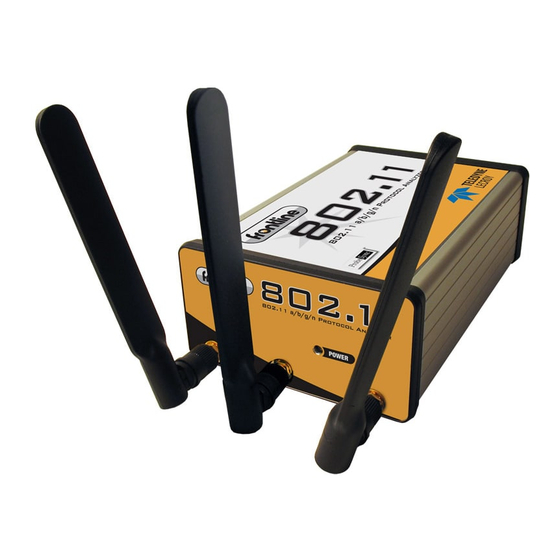
2.1 802.11 Hardware 2.1.1 Attaching Antennas When you remove the Frontline 802.11 from the box, the first step is to attach the antennas (Figure 2.1). Figure 2.1 - Front Panel 1. Attach an antenna to each front panel connector. -
Page 10: Connecting/Powering The Frontline
Figure 2.2 - Frontline 802.11 with both antennas attached 2.1.2 Connecting/Powering the Frontline 802.11 Once you have attached the antennas, the next step is to power up and connect the Frontline 802.11 to the computer. 1. Insert the power cable (DC connector) from the 12 volt AC adapter into the Power port on the Frontline 802.11 back panel (Figure 2.3). -
Page 11: Setting Up For Probesync
4. Insert the other end of the USB cable into the PC. 5. It may take as long as thirty seconds for Windows to recognize that the Frontline 802.11 hardware is connected to the PC. The Activity light on the Frontline 802.11 front panel (Figure 2.1 will blink during this period, when the light is steady, the Frontline 802.11 hardware is ready to communicate with the... - Page 12 1. Using a CAT 5 Ethernet cable (less than 1.5 meters (4.9 feet)) insert one end to the master Frontline device OUT jack. 2. Insert the other end of the cable into the slave Frontline device IN jack. Figure 2.5 - Back Panel - ProbeSync with BPA 600 Frontline 802.11 Hardware & Software User Manual...
-
Page 13: Data Capture Methods
Chapter 2 Getting Started TELEDYNE LECROY 2.2 Data Capture Methods This section describes how to load TELEDYNE LECROY Frontline Protocol Analysis System software, and how to select the data capture method for your specific application. 2.2.1 Opening Data Capture Method On product installation, the installer creates a folder on the windows desktop labeled "Frontline <version #>". - Page 14 Note: If you don't need to identify a capture method, then click the Run button to start the analyzer. Creating a Shortcut A checkbox labeled Create Shortcut When Run is located near the bottom of the dialog. This box is un-checked by default. Select this checkbox, and the Frontline 802.11 Hardware & Software User Manual...
-
Page 15: Frontline® 802.11 Data Capture Method
DecoderScript™, application notes), user documentation (Quick Start Guides and the Frontline User Manual), and maintenance tools. ® 2.2.2 Frontline 802.11 Data Capture Method 802.11 Requires one Frontline 802.11 hardware. Captures 802.11 data on the selected channel. Frontline 802.11 Hardware & Software User Manual... -
Page 16: Virtual Sniffing
802.11 with USB Requires one Frontline 802.11 and one Frontline USB hardware. 802.11 with USB and SD Requires one Frontline 802.11, one Frontline USB, and one Frontline SD hardware. 2.2.3 Virtual Sniffing ® The Virtual Sniffer is a live import facility within Frontline software that makes it possible to access any layer in a stack that the programmer has access to and feed this data into the Virtual Sniffer. -
Page 17: Control Window Toolbar
Save - Saves the capture file. Clear - Clears or saves the capture file. Event Display - (framed data only) Opens a Event Display, with the currently selected bytes highlighted. Frontline 802.11 Hardware & Software User Manual... -
Page 18: Configuration Information On The Control Window
The second half of the status bar gives the current utilization and total number of events seen on the network. This is the total number of events monitored, not the total number of events captured. The Frontline 802.11 Hardware & Software User Manual... -
Page 19: Frame Information On The Control Window
".frm file", the companion file to the ".cfa file". Recreating the ".frm file" helps ensure that the decoders will work properly. Reload Decoders The plug-ins are reset and received frames are decoded again. Frontline 802.11 Hardware & Software User Manual... - Page 20 Notes Notes window Capture Ctrl- Opens the that allows the user to add File Shift-O comments to a capture file. The Live menu selections will vary depending on the Frontline analyzer in use. Frontline 802.11 Hardware & Software User Manual...
- Page 21 Shift-F5 Begins data capture from the configured wireless devices. Stop Capture Stops data capture from the configured wireless devices. The following rows apply to all Frontline products Live Clear Shift- Clears or saves the capture file. Frontline 802.11 Hardware & Software User Manual...
- Page 22 When unchecked, the analyzer Request Missing Decoder decodes each frame until it cannot go further and it stops Information decoding. This selection is not present if no decoder is loaded that supports this feature. Frontline 802.11 Hardware & Software User Manual...
-
Page 23: Minimizing Windows
Control window is minimized, all windows are minimized. 3. Select the menu item again to deactivate this feature. 4. The windows minimize to the top of the operating system Task Bar. Frontline 802.11 Hardware & Software User Manual... - Page 24 TELEDYNE LECROY Chapter 2 Getting Started Frontline 802.11 Hardware & Software User Manual...
-
Page 25: Chapter 3 Configuration Settings
Note: Upon launching the Air Sniffer, the first device in the drop-down is the default device. 3.1.2 802.11 I/O Settings - Datasource 1. Select I/O Settings from the Options menu on the Control window. Frontline 802.11 Hardware & Software User Manual... - Page 26 If a parameter is changed (e.g. Channel 1 is changed to 6), the new setting appears the next time the I/O Settings dialog is opened for the device. The settings are saved when the OK button is pressed. 3.1.2.1 Settings Frontline 802.11 Hardware & Software User Manual...
- Page 27 Clicking on the Scanner button will open the Wi-Fi Scanner dialog. This action is useful if you do not know the channel to sniff. Once you have selected a channel in the Wi-Fi Scanner dialog and confirmed your selection the selected channel will appear in Channel. Frontline 802.11 Hardware & Software User Manual...
- Page 28 You can select/deselect which filters are active by checking/unchecking the Enable checkbox in the first column in the table. You can also select to ignore Management, Control, Data, and Reserved frame types by selecting one or more the checkboxes. Frontline 802.11 Hardware & Software User Manual...
- Page 29 Figure 3.5 - 802.11 I/O Settings Capture Filters Tab To create a key, select one of the following options: Add New Address - displays a text box where you can enter the address Frontline 802.11 Hardware & Software User Manual...
- Page 30 Edit Address - Highlight an address that you want to edit and select Edit to bring up a dialog where you can edit the address. The address and any of the prior settings may be changes. Click OK to save and close. Frontline 802.11 Hardware & Software User Manual...
-
Page 31: Firmware Update
1. This tab displays the current firmware version in the hardware. You can check for the firmware updates by first noting the current version and then clicking on the Check For Updates button. Frontline 802.11 Hardware & Software User Manual... - Page 32 Figure 3.8 - 802.11 I/O Settings Firmware Update Tab 2. The Check for Updates dialog will open. If an update is available you can install it by clicking on the Start Update button. Frontline 802.11 Hardware & Software User Manual...
- Page 33 6. Once the ComProbe 802.11 has reset, select I/O Settings from the Control Window Options menu. 7. Click on the I/O Settings dialog Firmware Update tab and then click on the Check for Updates button. The Check for Updates dialog will appear. Frontline 802.11 Hardware & Software User Manual...
- Page 34 12. Once the ComProbe 802.11 has reset, select I/O Settings from the Control Window Options menu. 13. Click on the I/O Settings dialog Firmware Update tab and then click on the Check for Updates button. The Check for Updates dialog will appear again. Frontline 802.11 Hardware & Software User Manual...
- Page 35 With ComProbe 802.11, the WiFi decryption is not done in the datasource. It is done in the decoders, so you must go to Set Initial Decoder Parameters to provide the security information to the decoder. Frontline 802.11 Hardware & Software User Manual...
- Page 36 Mbps by using additional wireless radio technologies. Pre- The pre-shared key is a 32-byte hex number. shared Within the Set Initial Decoder Parameters... dialog Security tab, the fields available will depend on the Encrypted Data option selected. Frontline 802.11 Hardware & Software User Manual...
- Page 37 Enter the required security data in to the active fields for the selected Encrypted Data option. Click the OK button to set the decoder security parameters. Wi-Fi security settings are also presented in detail in the Decoder Parameters section (See Wi-Fi Security Decoder Parameters on page 40). Frontline 802.11 Hardware & Software User Manual...
- Page 38 The Wi-Fi Device Scanner dialog displays a list of discoverable Wi-Fi devices in a table. The devices are identified by: MAC Address SSID Type Channel Frequency RSSI First Seen Last Seen Note: You can select the Stop or Stop Scanning from the Configure menu anytime to stop the device search. Frontline 802.11 Hardware & Software User Manual...
- Page 39 The Hardware Settings dialog provides the ability to select a device to sniff/scan. The dialog only lists devices with a MAC address that match the Frontline devices. To access the Hardware Settings dialog: 1. Select Hardware Settings from the Options menu on the 802.11 Control window. Frontline 802.11 Hardware & Software User Manual...
- Page 40 Channel listen time is how long Frontline 802.11 will listen on a channel to discover devices before moving on to the next channel. 4. Select Yes or No to choose whether to send a probe sync request. Frontline 802.11 Hardware & Software User Manual...
-
Page 41: Wi-Fi Device - Mac Address Editor
If you know the MAC Address of the device you can enter it manually. 1. From the I/O Settings dialog select the "Edit" button. 2. On the MAC Address Editor enter the MAC Address for the device. Frontline 802.11 Hardware & Software User Manual... -
Page 42: Decoder Parameters
For help on setting the parameters, click the Help button on each tab to get help information specific to that decoder. If you need to change the parameters later, Choose Set Initial Decoder Parameters... from the Options menu on the Control and Frame Display windows. Frontline 802.11 Hardware & Software User Manual... - Page 43 Select the frame where the change should take effect Select Set Subsequent Decoder Parameters... from the Options menu, and make the needed changes. You can also right-click on the frame to select the same option. Frontline 802.11 Hardware & Software User Manual...
-
Page 44: Decoder Parameter Templates
If you do not have decoders loaded that require parameters, the menu item does not appear and you don't need to worry about this feature. 3.2.1 Decoder Parameter Templates 3.2.1.1 Select and Apply a Decoder Template Frontline 802.11 Hardware & Software User Manual... - Page 45 The system saves the parameter changes to the template and closes the Save As dialog. 4. Click the OK button on the Set Initial Decoder Parameters window to apply the template and close the window. Frontline 802.11 Hardware & Software User Manual...
-
Page 46: Wi-Fi Security Decoder Parameters
ComProbe software uses the link from the BR/EDR connection. To automatically decode 802.11 AMP frames in this case, select the Bluetooth AMP Encrypted Data, but leave the Link Key field blank. Frontline 802.11 Hardware & Software User Manual... - Page 47 Enter a 32-byte hex number Shared WEP : The station ID of the 802.11 communications link. SSID WEP : The shared passkey phrase used in communications. Passkey Figure 3.24 - Decoder WiFi Security Tab Frontline 802.11 Hardware & Software User Manual...
-
Page 48: Adding Or Changing Tcp/Udp Port Assignments
4. Change the port number and/or choose the protocol to traverse to. 5. Select the Port Range radio button and specify the starting and ending port numbers. The range is inclusive. 6. Click the Modify button. The system displays the changes in port assignment. Frontline 802.11 Hardware & Software User Manual... -
Page 49: Determining Master And Slave
“Conductive” in this context means that you are not “air sniffing”, that is, capturing Wi-Fi transmissions on the Frontline analyzer's antenna. The conductive test setup uses coaxial cable to directly connect the Device Under Frontline 802.11 Hardware & Software User Manual... -
Page 50: Wifi Conductive Testing
5. Frontline 802.11 WiFi protocol analyzer. 6. Computer for running Frontline software. Test Setup Figure 3.25 below shows the 802,11 conductive test setup. Figure 3.25 - Frontline 802.11 Conductive Test Setup for 3X3 MIMO Frontline 802.11 Hardware & Software User Manual... - Page 51 DUTs and the ComProbe 802.11 is not used. Test Process After connecting DUT1, DUT2, and the Frontline 802.11 , follow these steps to capture WiFi data. 1. Establish data transmission between DUT 1 and DUT 2. 2. Begin capture of the data with the Frontline 802.11 .
- Page 52 TELEDYNE LECROY Chapter 3 Configuration Settings Frontline 802.11 Hardware & Software User Manual...
-
Page 53: Chapter 4 Capturing And Analyzing Data
Mitigating path loss and interference Bluetooth device design contributes to mitigating environmental effects on propagation through spread spectrum radio design, for example. However, careful planning of the testing environment can also contribute to reliable data capture process. Frontline 802.11 Hardware & Software User Manual... - Page 54 Wi-Fi interference should be minimized or eliminated. Bluetooth shares the same 2.4 GHz frequency bands as Wi-Fi technology. Wi-Fi interference can cause loss of packets and poor captures. In a laboratory or testing Frontline 802.11 Hardware & Software User Manual...
-
Page 55: Capturing Data To Disk - General Procedure
The display does not refresh when a new capture file in a series is created. Frontline 802.11 Hardware & Software User Manual... - Page 56 Unlike 802.11, Bluetooth packets never come in faster than the datasource can process them. However, Bluetooth packets must still be stored so that they can be read in chronological order with the 802.11 packets. Frontline 802.11 Hardware & Software User Manual...
-
Page 57: Capturing Using Frontline Wi-Fi Datasource With Wireshark
Click on the "ComProbe 802.11 with Wireshark" short cut to launch and start capturing the Wi-Fi packets. If you do not see any packets on the Wireshark window then check the status message indication on the Wi-Fi Datasource window to see if sniffing has stopped. Click on the Start button . Frontline 802.11 Hardware & Software User Manual... - Page 58 When the ComProbe 802.11 is sniffing the datasource will display the following message. Sniffing can be stopped by clicking the Stop button Figure 4.5 - Datasource Sniffing Figure 4.6 - Wireshark Capture Dialog Frontline 802.11 Hardware & Software User Manual...
- Page 59 Options dialog), if you move the Wireshark window around on the desktop or click on anything on the Wireshark window, it freezes the desktop. You can unfreeze it by bringing up Windows Task Manager by pressing Ctrl+Alt+Delete. Frontline 802.11 Hardware & Software User Manual...
-
Page 60: Combining Bpa 600, 802.11, And Hsu With Probesync
BPA 600 is always the "master" device and the first device in the chain, if being used. HSU is always the last "slave" device in the chain, if being used. HSU maximum capture data rate is 6 Mbit/sec. Frontline 802.11 Hardware & Software User Manual... - Page 61 802.11 and HSU devices. On the 802.11 and HSU receiving the clock—cable connected to IN— the Start Sniffing button is disabled when using ProbeSync. In each ComProbe device's Control window status window will announce the synchronizing function. Frontline 802.11 Hardware & Software User Manual...
-
Page 62: Sodera & 802.11: Capturing With Probesync
Timeline, Bluetooth low energy Timeline, and Coexistence View. Data saved as a capture file during analysis will include data captured on both devices. 4.1.6 Extended Inquiry Response Extended Inquiry Response (EIR) is a tab that appears automatically on the Frame Display window when you capture data. Frontline 802.11 Hardware & Software User Manual... -
Page 63: Protocol Stacks
Note: If a Bluetooth device does not support Extended Inquiry Response, the tab displays Received Signal Strength Indication (RSSI) data, which is less extensive than EIR data. 4.2 Protocol Stacks Frontline 802.11 Hardware & Software User Manual... -
Page 64: Protocol Stack Wizard
You cannot select a stack or change an existing one for a capture file loaded into the Capture File Viewer (the Capture File Viewer is used only for viewing capture files and cannot capture data). Protocol Stack changes can only be made from a live session. Frontline 802.11 Hardware & Software User Manual... -
Page 65: Creating And Removing A Custom Stack
1. Click the All additional stack layers can be determined automatically button. 2. If your protocol stack is complete and there are no additional layers, click the There are no additional stack layers button. Frontline 802.11 Hardware & Software User Manual... -
Page 66: Reframing
This function removes start-of-frame and end-of-frame markers from your data. The original capture file is not altered during this process. You cannot unframe from the Capture File Viewer (accessed by selecting Capture File Frontline 802.11 Hardware & Software User Manual... -
Page 67: How The Analyzer Auto-Traverses The Protocol Stack
Connect frames and stores the PSM along with the associated source and destination channel IDs. In this case the analyzer does not need to see the SDP process, but does need to see the L2CAP connection process, giving the source and destination channel IDs. Frontline 802.11 Hardware & Software User Manual... -
Page 68: Providing Context For Decoding When Frame Information Is Missing
- The Summary Pane displays a one line summary of each frame for every protocol found in the data, and can be sorted by field for every protocol. Click here for an explanation of the symbols next to the frame numbers. Frontline 802.11 Hardware & Software User Manual... - Page 69 The tabs disappear when the capture buffer is cleared during live capture or when decoders are reloaded, even if one of the tabs is currently selected. They subsequently reappear as the corresponding events are detected. Frontline 802.11 Hardware & Software User Manual...
- Page 70 Save - Save the currently selected bytes or the entire buffer to file. Clear- Discards the temporary file and clears the display. Event Display – Brings the Event Display window to the front. Show Statistics - Opens Statistics dialog Frontline 802.11 Hardware & Software User Manual...
- Page 71 Extract Data - Opens the Extract Data dialog. Audio Extraction - Opens the Audio Extraction dialog. Pie Chart - This icon displays a chart that displays the number of frames with and without errors. Frontline 802.11 Hardware & Software User Manual...
- Page 72 Next Frame - Moves to the next frame in the buffer. Last Frame - Moves to the last frame in the buffer. Find on Frame Display only searches the Decode Pane for a value you enter in the text box. Frontline 802.11 Hardware & Software User Manual...
- Page 73 Total Frames: The total number of frames in the capture buffer or capture file in real-time Frames Filtered In: The total number of frames displayed in the filtered results from user applied filters in real-time Frontline 802.11 Hardware & Software User Manual...
- Page 74 Frame Display has a simple Find function that you can use to search the Decode Pane for any alpha numeric value. This functionality is in addition to the more robust Search/Find dialog. Frame Display Find is located below the toolbar on the Frame Display dialog. Frontline 802.11 Hardware & Software User Manual...
- Page 75 Note: The text box is disabled during a live capture. 3. Select Find Previous Occurrence to begin the search on frames prior to the frame you selected, or Find Next Occurrence to begin the search on frames following the frame you selected. Frontline 802.11 Hardware & Software User Manual...
- Page 76 The Frame Display is synchronized with the Event Display. Click on a frame in the Frame Display and the corresponding bytes is highlighted in the Event Display. Each Frame Display has its own Event Display. As an example, here's what happens if the following sequence of events occurs. Frontline 802.11 Hardware & Software User Manual...
- Page 77 Show All Panes from the View menu). The Toggle Expand Decode Pane icon makes the decode pane longer to view lengthy decodes better. The Show Default Panes icon returns the Frame Display to its default settings. Frontline 802.11 Hardware & Software User Manual...
- Page 78 Filter tab above the Summary pane. Filtered-out frames are not exported. Selected Frames export is the same as All Frames export except that only frames selected in the Summary pane will be exported. Frontline 802.11 Hardware & Software User Manual...
- Page 79 The body shows the frame number, the timestamp in the same format shown in the Frame Display Summary pane, and the frame contents as raw bytes. Frontline 802.11 Hardware & Software User Manual...
- Page 80 These tabs are arranged in separate color-coded groups. These groups and their colors are General (white), Classic Bluetooth (blue), Bluetooth low energy (green), 802.11 (orange), USB (purple), and SD (brown). The General group applies to all technologies. The other groups are technology-specific. Figure 4.22 - Example Protocol Tags Frontline 802.11 Hardware & Software User Manual...
- Page 81 Figure 4.23 - Summary pane (right) with Tooltip on Column 5 (Tran ID) 4.3.1.11.2 Customizing Fields in the Summary Pane You can modify the Summary Pane in Frame Display. Summary pane columns can be reordered by dragging any column to a different position. Frontline 802.11 Hardware & Software User Manual...
- Page 82 To restore columns to their default locations, their default widths, and show any hidden columns 1. Right-click on any column header and choose Restore Default Column Widths, or select Restore Default Column Widths from the Format menu. Frontline 802.11 Hardware & Software User Manual...
- Page 83 Click the Toggle Expand Decode Pane icon to make the Decode pane taller. This allows for more of a lengthy decode to be viewed without needing to scroll. Frontline 802.11 Hardware & Software User Manual...
- Page 84 The Event, Radix, Binary, Character and Decode panes are all synchronized with one another. Clicking on an element in any one of the panes highlights the corresponding element in all the other panes. Frontline 802.11 Hardware & Software User Manual...
- Page 85 The protocol name for each layer in the Decode pane is in the same color. Note that the colors refer to the layer, not to a specific Frontline 802.11 Hardware & Software User Manual...
- Page 86 1. Display filters allow a user to look at a subset of captured data without affecting the capture content. Frames matching the filter criteria appear in the Frame Display; frames not matching the criteria will not Frontline 802.11 Hardware & Software User Manual...
- Page 87 Named filters are persistent across sessions. Named filters are user-defined. User-defined filters persist in a template file. User defined filters can be deleted. Frontline 802.11 Hardware & Software User Manual...
- Page 88 Figure 4.26 - Example: Set Conditions Self Configuring Based on Frame Range 2. Select Include or Exclude to add filtered data or keep out filtered data respectively. 3. Select the initial condition for the filter from the drop-down list. Frontline 802.11 Hardware & Software User Manual...
- Page 89 1. Select a frame in the Frame Display Summary Pane. 2. Right click in the one of the data columns in the Summary Pane: CRC, NESN, DS, Packet Success, Ethertype, Source Address, etc. Frontline 802.11 Hardware & Software User Manual...
- Page 90 Continue to enter the requested parameters in the fields provided until the conditions statement is complete. Figure 4.27 - Two Filter Conditions Added with an AND Operator Frontline 802.11 Hardware & Software User Manual...
- Page 91 2. From the Select each frame combo box choose frames with the conversation as the initial condition. 3. Select an address type—IP, MAC, TCP/UDB—from the Typecombo box (The address type selection populates both Address combo boxes with node address in the data set that match the type selection). Frontline 802.11 Hardware & Software User Manual...
- Page 92 4. Click OK. The Delete Named Condition dialog box closes and the system deletes the filter. Hiding and Revealing Display Filters If a display filter is showing the following steps will hide that filter but will not delete it. Frontline 802.11 Hardware & Software User Manual...
- Page 93 Frame Display windows. You must use the Hide/Show dialog to display a filter created in one Frame Display in different Frame Display window. Frontline 802.11 Hardware & Software User Manual...
- Page 94 Boolean format. The dialog box displays the current filter definition. To display another filter, click the Open icon, and select the filter from the pop-up list of all the saved filters. Frontline 802.11 Hardware & Software User Manual...
- Page 95 Rename Filter dialog. The system displays the Rename Filter dialog with a list of all user defined filters in the Filters combo box. Figure 4.31 - Rename Filters Dialog 2. Select the filter to be renamed from the combo box. Frontline 802.11 Hardware & Software User Manual...
- Page 96 Access Addresses displays all the low energy slave device's access address. You can select only one access address to filter. The selected link will filter in only the frames associated with that access address. Frontline 802.11 Hardware & Software User Manual...
- Page 97 Right-click anywhere in a Frame Display pane and select Connection Filter in the pop-up menu. The procedure for creating a connection filter are identical as described in From the Frame Display Filter menu, above. Frontline 802.11 Hardware & Software User Manual...
- Page 98 Clicking on Connection Filter Link = 4 will filter in "Link 4" frames without opening all the drop-down menus. Frontline 802.11 Hardware & Software User Manual...
- Page 99 The new Frame Display with the filtered connection frames will only contain the data defined by the filter criteria. That is, the criteria could be a single link or data for a particular technology. Frontline 802.11 Hardware & Software User Manual...
- Page 100 In this example, there is a capture file with Classic Bluetooth, Bluetooth low energy, and 802.11. To view just the 802.11 data set, 802.11 = All is selected from the right-click pop up menu. Frontline 802.11 Hardware & Software User Manual...
- Page 101 On the Frame Display , click the Quick Filtering icon or select Quick Filtering from the Filter menu. This opens a dialog that lists all the protocols discovered so far. The protocols displayed change depending on the data received. Frontline 802.11 Hardware & Software User Manual...
- Page 102 Summary pane, and the second lets you filter on any protocol discovered on the network so far. Filtering on the Summary Layer Protocol To filter on the protocol in the Summary in the Frame Display window pane: Frontline 802.11 Hardware & Software User Manual...
-
Page 103: Coexistence View
The Coexistence View displays Classic Bluetooth, Bluetooth low energy, and 802.11 packets and throughput in one view. You access the Coexistence View by clicking its button in the Control window or Frame Display toolbars, or Coexistence View from the View menus. Frontline 802.11 Hardware & Software User Manual... - Page 104 Table 4.4 - Coexistence View Format Menu Selections Selection Description Show Packet When checked, the packet number shows below the packet in the Viewport. Number Show Packet When checked, the packet type shows below the packet in the Viewport. Type Frontline 802.11 Hardware & Software User Manual...
- Page 105 Performs the same function as the Throughput Packet radio button. Show Payload When checked, the Throughput Graph and Throughput Indicator shows data based on Throughput payload throughput. Performs the same function as the Throughput Payload radio button. Frontline 802.11 Hardware & Software User Manual...
- Page 106 Graph When not checked, the Throughput Graph appears in its default position at the top of the window. Performs the same function as clicking the Swap button. See on page 112. Frontline 802.11 Hardware & Software User Manual...
- Page 107 Scroll Tool (Mouse Wheel Scrolls - Ctrl Key When checked, sets the mouse wheel to scroll Switches to Zoom Tool) the Viewport. Pressing the Ctrl key while scrolling switches to zooming the Viewport. Frontline 802.11 Hardware & Software User Manual...
- Page 108 Custom Zoom (Set by Zoom To Time Range of Automatically checked when taking any zoom Selected Packets, Zoom To Throughput Graph action other than the fixed Viewport zoom Data Point, or dragging Viewport Slide) durations listed below. Frontline 802.11 Hardware & Software User Manual...
- Page 109 4 sec (6,400 Bluetooth slots) 5 sec (8,000 Bluetooth slots) 10 sec (16,000 Bluetooth slots) 20 sec (32,000 Bluetooth slots) Note: Right-clicking anywhere in the Coexistence View window will open the Zoom menu in a pop-up. Frontline 802.11 Hardware & Software User Manual...
- Page 110 When clicked, selects the first prior packet with Ctrl+Left Arrow Error Packet an error from the current selection and displays it in the Timeline. Performs the same function as Previous Error Packet button. Frontline 802.11 Hardware & Software User Manual...
- Page 111 Next Packet and the Last Packet selections are active, but the Previous Packet selection is inactive. 4.3.2.2 Coexistence View - Toolbar Figure 4.41 - Coexistence View Toolbar The toolbar contains the following selections: Frontline 802.11 Hardware & Software User Manual...
- Page 112 Move to the previous packet of the type selected in the legend Move to the next packet of the type selected in the legend. Move to the last packet of the type selected in the legend. Zoom in. Zoom out. Scroll cursor. Frontline 802.11 Hardware & Software User Manual...
- Page 113 Bluetooth low energy, and 802.11. 4.3.2.4 Throughput Throughput is total packet or payload size in bits of the included packets divided by the duration of the included packets, where: Frontline 802.11 Hardware & Software User Manual...
- Page 114 1 second duration ending at the end of the last packet in the viewport time range are used for 1 second throughput, except that Bluetooth low energy packets from non-configured devices can be excluded as noted above. Frontline 802.11 Hardware & Software User Manual...
- Page 115 Figure 4.45 - Average throughput indicators show a plus sign (+) when the indicator width is exceeded. Figure 4.46 - A single selected packet (Click here to see a video on how the Throughput is calculated...) 4.3.2.10 Coexistence View - Throughput Graph (Click here to see aThroughput Graph video...) Frontline 802.11 Hardware & Software User Manual...
- Page 116 For example, if a data point has a duration of 0.1 s and a bit count of 100, it will have a throughput of 1,000 bits/s, and the y-axis labels will be consistent with this. Figure 4.48 - Throughput Graph y-axis labels. Frontline 802.11 Hardware & Software User Manual...
- Page 117 4.01 s is called a positive discontinuity and is shown in black. A positive discontinuity is a cosmetic nicety to avoid lots of empty space. A negative discontinuity is an error. Figure 4.50 - A negative discontinuity. Frontline 802.11 Hardware & Software User Manual...
- Page 118 4.3.2.16 Swap button The Throughput Graph and Timeline can be made to trade positions by clicking the Swap button. Clicking the Swap button swaps the positions of the Throughput Graphs and the Timelines. Frontline 802.11 Hardware & Software User Manual...
- Page 119 A tooltip can be displayed for each dot. Dots can be removed for greater visibility of the plots when data points are crowded together. Figure 4.54 - Dots Toggled On and Off Frontline 802.11 Hardware & Software User Manual...
- Page 120 Timelines are synchronized with the Throughput Graph’s viewport. The viewport is sized by dragging one of its sides or by using one of the other zooming techniques listed in the Zooming subsection in the Timelines section. Frontline 802.11 Hardware & Software User Manual...
- Page 121 Unfreeze Y and a Y Scales Frozen indicator appears to the right of the title. Clicking the Unfreeze Y button unfreezes the y-axis scales. Figure 4.57 - Zoomed Throughput Graph- Largest Value Snaps to Top Frontline 802.11 Hardware & Software User Manual...
- Page 122 This mismatch can result in the data for a particular packet being included in different intervals in the two Throughput Graphs, and can have a significant impact on the shapes of the two respective graphs. This can also result in the total duration of the two Throughput Graphs being different. Frontline 802.11 Hardware & Software User Manual...
- Page 123 Set button is clicked. Also listed is the last source MAC address that was set in the dialog in the previous session. If that address has not yet been seen in this session, it is shown in parentheses. Figure 4.59 - 802.11 Source Address Dialog Frontline 802.11 Hardware & Software User Manual...
- Page 124 Bluetooth low energy packets. The All radio button shows and uses all Bluetooth low energy packets. The Configured radio button shows and uses only Bluetooth low energy packets which come from a configured device. Frontline 802.11 Hardware & Software User Manual...
- Page 125 4.3.2.26 Coexistence View – Timelines (Click here to see a Coexistence View Timeline video...) Figure 4.62 - Coexistence View Timelines The Timelines show Classic Bluetooth® , Bluetooth low energy, and 802.11 packets by channel and time. Frontline 802.11 Hardware & Software User Manual...
- Page 126 Selecting a packet by clicking on it draws a selection box around it (as shown above) and highlights the applicable entries in the legend. Figure 4.64 - Highlighted entries in the legend for a selected packet. Summary information for a selected packet is displayed in the timeline header. Frontline 802.11 Hardware & Software User Manual...
- Page 127 Number, Show Packet Type, and Show Packet Subtype from the Format menu. Figure 4.67 - Descriptive text on timeline packets. Placing the mouse pointer on a packet displays a tooltip (color-coded by technology) that gives detailed information. Frontline 802.11 Hardware & Software User Manual...
- Page 128 Screen, and any time you mouse-over a packet the tool tip will appear anchored in the upper-left corner of the computer screen. To return to viewing the tool tip adjacent to the packets deselect the tool tip format option in the menu. Frontline 802.11 Hardware & Software User Manual...
- Page 129 Chapter 4 Capturing and Analyzing Data TELEDYNE LECROY Figure 4.69 - Coexistence View Format Menu - Show Tooltips on Computer Screen Frontline 802.11 Hardware & Software User Manual...
- Page 130 There are two Timelines available for viewing, one for the 5 GHz range and one for the 2.4 GHz range. Classic Bluetooth and Bluetooth low energy occur only in the 2.4 GHz range. 802.11 can occur in both. Frontline 802.11 Hardware & Software User Manual...
- Page 131 The header shows information for packets that are selected. The footer shows the beginning/ending timestamps and visible duration of the timelines. The ‘i’ buttons bring up channel information windows, which describe channel details for each technology. They make for interesting reading. Frontline 802.11 Hardware & Software User Manual...
- Page 132 When zoomed in far enough Bluetooth slot markers appear in the 2.4 GHz timeline. A Bluetooth slot is 625 µs wide. Figure 4.74 - Vertical blue lines are Bluetooth slot markers 4.3.2.31 Zooming There are various ways to zoom: Frontline 802.11 Hardware & Software User Manual...
- Page 133 A discontinuity for a timestamp going forward by more than 4.01 s is called a positive discontinuity and is shown in black. A positive discontinuity is a cosmetic nicety to avoid lots of empty space. A negative discontinuity is an error. Figure 4.75 - A negative discontinuity Frontline 802.11 Hardware & Software User Manual...
- Page 134 High-speed Bluetooth packets, where Bluetooth content hitches a ride on 802.11 packets, have a blue frequency range box instead of orange as with regular 802.11 packets (both are shown below), and the tool tip has two colors, orange for 802.11 layers and blue for Bluetooth layers. Frontline 802.11 Hardware & Software User Manual...
- Page 135 High Speed mode. 1. Click on the Control window File menu and select Close. 2. The Control window will open again. Click on the Control Window File menu and select Go Live (High- Speed Mode) Frontline 802.11 Hardware & Software User Manual...
- Page 136 3. Click on the Control window Start Capture button to begin capturing data. Click on the Coexistence View button and the High-Speed View will appear. The Coexistence View (High Speed Live Mode) window will appear. Figure 4.80 - High-Speed Live Window Frontline 802.11 Hardware & Software User Manual...
-
Page 137: Analyzing Byte Level Data
Event Display is synchronized with the Frame Display and Mesage Sequence Chart dialogs. Selecting a byte in Event Display will also select the related frame in the Frame Display and the related message in the Message Sequence Chart. Frontline 802.11 Hardware & Software User Manual... -
Page 138: The Event Display Toolbar
DTE data is still shown with a white background and DCE data with a gray background so that you can distinguish between the two. The benefit of using this format is that more data fits onto one screen. Frontline 802.11 Hardware & Software User Manual... -
Page 139: Opening Multiple Event Display Windows
6. Click OK to generate the CRC. It appears in the byte information lines at the bottom of the Event Display window. Whenever you select a range of data, a CRC using the algorithm you selected is calculated automatically. Calculating CRC for interwoven data Frontline 802.11 Hardware & Software User Manual... -
Page 140: Calculating Delta Times And Data Rates
You can have more than one Event Display or Frame Display window open at a time. Click the Duplicate View icon to open additional Event or Frame Display windows. The lock/resume function is independent on Frontline 802.11 Hardware & Software User Manual... -
Page 141: Data Formats And Symbols
I/O Settings changes and Data Capture Paused and Resumed. The base of a number system. Binary is base 2, octal is base 8, decimal is base 10 and hexadecimal is base 16. Frontline 802.11 Hardware & Software User Manual... - Page 142 Data from one side (Slave ) is shown on a white background and data from the other side ( Master )is shown on a gray background. Frontline 802.11 Hardware & Software User Manual...
- Page 143 An event is anything that happens on the circuit or which affects data capture. Data bytes, control signal changes, and long and short breaks are all events, as are I/O Settings changes and Data Capture Paused and Resumed. Frontline 802.11 Hardware & Software User Manual...
- Page 144 Timestamping Disabled - Timestamping was turned off. Events following this event are not timestamped. Timestamping Enabled - Timestamping was turned on. Events following this event have timestamps. Truncated Frame- A frame that is not the same size as indicated within its protocol. Underrun Error Frontline 802.11 Hardware & Software User Manual...
-
Page 145: Data/Audio Extraction
Then you can examine the specific files information individually. 1. You access this dialog by selecting Extract Data/Audio from the View menu or by clicking on the icon from the toolbar Frontline 802.11 Hardware & Software User Manual... - Page 146 If this option is not selected, the audio packets are extracted without inserting the silence packets for the reserved empty slots. Note: This option is for SCO/eSCO only. Frontline 802.11 Hardware & Software User Manual...
- Page 147 10. If you did not select this option, you can open a file by simply double-clicking on the name. Also, if a file type is unknown, you can select the file and it appears in the Rename to: text box. Frontline 802.11 Hardware & Software User Manual...
-
Page 148: Statistics
4.6 Statistics 4.6.1 Statistics Window The Statistics window supplies basic information about the data on the network. When reviewing a capture file, the Statistics window shows a summary of the data in the file. Frontline 802.11 Hardware & Software User Manual... - Page 149 The analyzer continues to monitor network traffic while the Statistics window is locked, so you may see the numbers jump right after updating has resumed, reflecting all the statistics that were gathered while the window was locked. Frontline 802.11 Hardware & Software User Manual...
- Page 150 Closes the Statistics Window ComProbe Protocol Analysis System Clicking on these selections will change the focus from the Statistics Statistics Window to the selected window. Errors Help Help Topics Opens the ComProbe Help window. Frontline 802.11 Hardware & Software User Manual...
-
Page 151: Session, Resettable And Capture File Tabs
Capture File tab become not available if the buffer becomes full and wraps. When this happens, the analyzer can no longer provide accurate statistics for the data in the file, because some of the data that the statistics are based on has been lost. Frontline 802.11 Hardware & Software User Manual... -
Page 152: Copying Statistics To The Clipboard
4.6.5.1 Statistics Errors Graphs Open the Statistics window and click on the picture of a graph on the Errors table header, or choose the graph name from the Graph menu on the Statistics window. Frontline 802.11 Hardware & Software User Manual... -
Page 153: Printing Error Graphs
Bar icon to display a bar graph. 4.6.5.2 Printing Error Graphs Click the Print icon to print the graph. The analyzer prints exactly what is shown in the window. Frontline 802.11 Hardware & Software User Manual... - Page 154 TELEDYNE LECROY Chapter 4 Capturing and Analyzing Data Frontline 802.11 Hardware & Software User Manual...
-
Page 155: Chapter 5 Navigating And Searching The Data
There has to be ways to manage the information. ComProbe software provides a number of different methods for making the data more accessible. One of these methods is Find. Figure 5.1 - Find Dialog Frontline 802.11 Hardware & Software User Manual... -
Page 156: Searching Within Decodes
Note: The tabs displayed on the Find dialog depend on the product you are running and the content of the capture file you are viewing. Figure 5.2 - Find Decode Tab Search for String Frontline 802.11 Hardware & Software User Manual... - Page 157 3. When you have specified the time interval you want to use, click on the Find Next or Find Previous buttons to start the search from the current event. The result of the search is displayed in the Decode pane in Frame Display. Frontline 802.11 Hardware & Software User Manual...
-
Page 158: Searching By Pattern
Search by Pattern lets you perform a traditional string search. You can combine any of the formats when entering your string, and your search can include wildcards. To access the search by pattern function: 1. Open a capture file to search. 2. Open the Event Display or Frame Display window. Frontline 802.11 Hardware & Software User Manual... - Page 159 ComProbe analyzer saves the search. The next time you open Find, the drop-down list will contain your search parameters. 1. Enter the search pattern. 2. Check Ignore Case to do a case-insensitive search. Frontline 802.11 Hardware & Software User Manual...
-
Page 160: Searching By Time
Note: The tabs displayed on the Find dialog depend on the product you are running and the content of the capture file you are viewing. Figure 5.6 - Find by Time tab The analyzer can search by time in several different ways. Search for Absolute/Relative timestamp. Frontline 802.11 Hardware & Software User Manual... - Page 161 The analyzer skips some special events that do not have timestamps, such as frame markers. Data events that do not have timestamps because timestamping was turned off either before or during capture are also skipped. Frontline 802.11 Hardware & Software User Manual...
-
Page 162: Using Go To
Figure 5.7 - Find Go To tab To go to a particular frame : 1. Select the Frame Number radio button 2. Type the frame number in the box. 3. Click the Go To button. Frontline 802.11 Hardware & Software User Manual... -
Page 163: Searching For Special Events
4. Click on the Special Events tab of the Find dialog. Note: The tabs displayed on the Find dialog depend on the product you are running and the content of the capture file you are viewing. Frontline 802.11 Hardware & Software User Manual... -
Page 164: Searching By Signal
1. Open a capture file to search. 2. Open the Event Display or Frame Display window. 3. Click on the Find icon or choose Find from the Edit menu. 4. Click on the Signal tab of the Find dialog. Frontline 802.11 Hardware & Software User Manual... - Page 165 TELEDYNE LECROY Note: The tabs displayed on the Find dialog depend on the product you are running and the content of the capture file you are viewing. Figure 5.9 - Find Signal tab. Frontline 802.11 Hardware & Software User Manual...
- Page 166 Searching for an event where one or more signals changed means that the analyzer looks at every control signal that you checked, and see if any one of those signals changed state at any time. Frontline 802.11 Hardware & Software User Manual...
- Page 167 Ready (DSR), Data Terminal Ready (DTR), Carrier Detect (CD), and Ring Indicator (RI). Click Find Next to locate the next occurrence of the search criteria or Find Previous to locate an earlier occurrence of the search criteria. Frontline 802.11 Hardware & Software User Manual...
-
Page 168: Searching For Data Errors
4. Click on the Errors tab of the Find dialog. Note: The tabs displayed on the Find dialog depend on the product you are running and the content of the capture file you are viewing. Figure 5.11 - Find Error tab. Frontline 802.11 Hardware & Software User Manual... - Page 169 If you are searching for an exact match, the analyzer asks you if you want to continue searching from the beginning of the buffer. Searching for Exact Error Conditions Frontline 802.11 Hardware & Software User Manual...
-
Page 170: Find - Bookmarks
4. Click on the Bookmarks tab of the Find dialog. Note: The tabs displayed on the Find dialog depend on the product you are running and the content of the capture file you are viewing. Frontline 802.11 Hardware & Software User Manual... -
Page 171: Changing Where The Search Lands
2. Go to the [CVEventDisplay] section 3. Change the value for SelectionOffset. 4. If you want the selection to land on the top line of the display, change the SelectionOffset to 0 (zero). Frontline 802.11 Hardware & Software User Manual... -
Page 172: Subtleties Of Timestamp Searching
4. Click OK. Once you create a bookmark it will be saved with the rest of the data in the .cfa file. When you open a .cfa file, the bookmarks are available to you. Frontline 802.11 Hardware & Software User Manual... -
Page 173: Displaying All And Moving Between Bookmarks
. Select the bookmark you want to move to and click the Go To button, or simply double-click on the bookmark. Click the Move Forward and Move Back buttons to cycle through the bookmarks. Frontline 802.11 Hardware & Software User Manual... - Page 174 Figure 5.14 - Find Window Bookmark tab Used to Move Around With Bookmarks To delete a bookmark, select it and click the Delete button. To modify a bookmark, select it and click the Modify button. Click Remove All to delete all the bookmarks. Frontline 802.11 Hardware & Software User Manual...
-
Page 175: Chapter 6 Saving And Importing Data
You cannot save data to file while it is being captured. 2. Open the Event Display or Frame Display window. 3. Click the Save icon, or select Save from the File menu. Frontline 802.11 Hardware & Software User Manual... -
Page 176: Saving The Entire Capture File With Save Selection
7. Type a file name in the As box at the bottom of the screen. Click the Browse icon to browse to a specific directory. Otherwise your file is saved in the default capture file directory. 8. When you are finished, click OK. Frontline 802.11 Hardware & Software User Manual... -
Page 177: Saving A Portion Of A Capture File
. This icon is present on the toolbars of the Frame Display , as well as the Event Display . Notes can be selected from the Edit menu on one of these windows. Frontline 802.11 Hardware & Software User Manual... -
Page 178: Confirm Capture File (Cfa) Changes
3. If the file is not in the File menu list, select Open Capture File from the File menu or simply click on the Open icon on the toolbar. 4. Capture files have a .cfa extension. Browse if necessary to find your capture file. 5. Click on your file, and then click Open. Frontline 802.11 Hardware & Software User Manual... -
Page 179: Importing Capture Files
When Print Preview is selected, the output displays in a browser print preview window, where the user can select from the standard print options. The output file format is in html, and uses the Microsoft Web Browser Control print options for background colors and images. Frontline 802.11 Hardware & Software User Manual... - Page 180 (click on and highlight) the layers from the list box. 4. Click on selected layers in the list to de-select, or click the Reset Selected Layers button to de-select all selected layers. Figure 6.2 - Frame Display Print Dialog Frontline 802.11 Hardware & Software User Manual...
- Page 181 2. From this point the procedure is the same as steps 2 through 5 in "How to Print Frame Display Data" above. 3. Click the OK button, and after a brief wait a browser window will appear. Frontline 802.11 Hardware & Software User Manual...
-
Page 182: Printing From The Event Display
Note: In order to prevent a Print crash, you cannot select All if there are more than 100,000 events in the capture buffer. Note: See "Configure the Print File Range in the Event Display Print Dialog" above for an explanation of these selections Frontline 802.11 Hardware & Software User Manual... -
Page 183: Exporting
With the Event Display Export dialog you can export the contents of the Event Display dialog as a test (.txt), CSV (.csv.), HTML (.htm), or Binary File (.bin). You also have the option of exporting the entire capture buffer or just the current selection of the Event Display dialog. Frontline 802.11 Hardware & Software User Manual... - Page 184 Choose Host, Function\Control or Both to determine how you want to export the data. 5. Choose Host, Function\Control or Both to determine how you want to export the data. 6. Choose whether you want to display multiple events or single events per row. Frontline 802.11 Hardware & Software User Manual...
- Page 185 7. If you select .csv as the file type, choose whether you want to hide/display Preambles or Column Headings in the exported file 8. Click Save. The Event Display Export file is saved to the locations you specified in File name. Frontline 802.11 Hardware & Software User Manual...
- Page 186 When exporting Baudot, you need to be able to determine the state of the shift character. In a text export, the state of the shift bit can be determined by the data in the Character field. When letters is active, the character field shows letters and vice versa. Frontline 802.11 Hardware & Software User Manual...
-
Page 187: Chapter 7 General Information
To enable a setting, click in the box next to the setting to place a checkmark in the box. To disable a setting, click in the box to remove the checkmark. When viewing a capture file, settings related to data capture are grayed out. Frontline 802.11 Hardware & Software User Manual... - Page 188 File Size: The size of the file will depend of the available hard disk space. 1. Click the Min button to see/set the minimum acceptable value for the file size. 2. Click the Max button to see/set the maximum acceptable value for the file size. Frontline 802.11 Hardware & Software User Manual...
- Page 189 To access the Advanced System Options: 1. Go to the Control window. 2. Choose System Settings from the Options menu. 3. On the System Settings window, click the Advanced button. Frontline 802.11 Hardware & Software User Manual...
- Page 190 1. Choose System Settings from the Options menu on the Control window. 2. On the System Settings window, click the Start Up button. 3. Choose one of the options to determine if the analyzer starts data capture immediately on starting up or not. Frontline 802.11 Hardware & Software User Manual...
-
Page 191: Changing Default File Locations
My Configurations. These locations are set at installation. Follow the steps below to change the default locations. 1. Choose Directories from the Options menu on the Control window to open the File Locations window. Frontline 802.11 Hardware & Software User Manual... - Page 192 2. Select the default location you wish to change. 3. Click Modify. 4. Browse to a new location. Figure 7.5 - File Locations Browse dialog 5. Click OK. 6. Click OK when finished. Frontline 802.11 Hardware & Software User Manual...
-
Page 193: Side Names
The Side Names dialog is used to change the names of objects and events that appear in various displays. The Side Names dialog will change depending on the sniffing technology in use at the time the software was loaded. Changes to the Names are used throughout the program. Frontline 802.11 Hardware & Software User Manual... -
Page 194: Timestamping
Choose Set Timestamp Format… from the Options menu on the Frame Display and Event Display window or click on the Timestamping Option icon in the Event Display toolbar. The Timestamping Options window will open. Frontline 802.11 Hardware & Software User Manual... - Page 195 To change timestamping resolutions: 1. Go to the Capture Options section of the window. 2. Change the resolution listed in the Frontline 802.11 Hardware & Software User Manual...
- Page 196 Selecting both values displays the total time in nanoseconds from the start of the capture as opposed to a specific point in time. Selecting neither value displays the actual chronological time. Frontline 802.11 Hardware & Software User Manual...
-
Page 197: Technical Information
Some windows require more processing time than others because the information being displayed in them is constantly changing. Refrain from displaying data live in the Event Display and Frontline 802.11 Hardware & Software User Manual... -
Page 198: Progress Bars
Since the events are not renumbered, your colleague’s file use the same event numbers that your file does. 7.2.4 Useful Character Tables 7.2.4.1 ASCII Codes Frontline 802.11 Hardware & Software User Manual... - Page 199 7.2.4.3 EBCDIC Codes 7.2.4.4 Communication Control Characters Listed below in alphabetical order are the expanded text meanings for common ANSI communication control characters, and two-character system abbreviation for each one. Some abbreviations have forward slash Frontline 802.11 Hardware & Software User Manual...
- Page 200 End of Transmission Block End of Text Form Feed File Separator Group Separator Horizontal Tabulation Line Feed Negative Acknowledge Null Record Separator Shift In Shift Out Start of Heading Start of Text Substitute Synchronous Idle Frontline 802.11 Hardware & Software User Manual...
-
Page 201: Decoderscript Overview
UUID is not unique. The ComProbe software detects and stores the relationships (mappings) between handle and UUID during the GATT discovery process. But sometimes, there is no GATT discovery process because Frontline 802.11 Hardware & Software User Manual... -
Page 202: Contacting Technical Support
Technical support is available in several ways. The online help system provides answers to many user related questions. Frontline's website has documentation on common problems, as well as software upgrades and utilities to use with our products. On the Web: http://fte.com/support/supportrequest.aspx Email: tech_support@fte.com Frontline 802.11 Hardware & Software User Manual... - Page 203 TELEDYNE LECROY If you need to talk to a technical support representative about your Frontline 802.11 product, support is available between 9 am and 5 pm, U.S. Eastern Time zone, and between 9 am and 5 pm, Pacific Time zone, on Monday through Friday.
- Page 204 TELEDYNE LECROY Chapter 7 General Information Frontline 802.11 Hardware & Software User Manual...
-
Page 205: Appendicies
Appendicies Appendix A: Application Notes Frontline 802.11 Hardware & Software User Manual... -
Page 206: Appendix A: Application Notes
TELEDYNE LECROY Appendicies Appendix A: Application Notes A.1 ComProbe Automation Server: Why use it? Frontline 802.11 Hardware & Software User Manual... - Page 207 Appendicies TELEDYNE LECROY Frontline 802.11 Hardware & Software User Manual...
-
Page 208: Comprobe Automation Server: Why Use It
Automatic exporting captured data – extracting specific data for post testing analysis outside of the ComProbe software, e.g. export to CSV. Automate other Windows – based applications while capturing data – for example, controlling other testing equipment related to the test. Automate regression testing. Frontline 802.11 Hardware & Software User Manual... -
Page 209: Automation Server Topology
This is typically located at C:\Program Files (x86)\Frontline Test System II\Frontline ComProbe Protocol Analysis System [your version]\Development Tools\. On 32-bit Windows or Windows XP the root installation folder is "C:\Program Files\". Frontline 802.11 Hardware & Software User Manual... - Page 210 Lastly, you need to identify the "personality" of the ComProbe hardware. On or about line 823 you will change the following code to replace the text within the quotes with the personality key that matches your sniffing hardware Frontline 802.11 Hardware & Software User Manual...
-
Page 211: Running Automation Server Script
823 to use ComProbe BPA 600 and ComProbe 802.11 in coexistence. This is equivalent to 1) double clicking on the Frontline desktop folder and starting the software and 2) selecting a capture method. Frontline 802.11 Hardware & Software User Manual... - Page 212 Master and Slave devices. If other parameters are omitted from the code the default values are selected. This line of code is equivalent to setting the BPA 600 datasource for Classic Bluetooth. ConfigSettings [format "IOParameters;BPA600;Master=0x00025b01cb8b;Slave=0x00025b01cbe1"] Frontline 802.11 Hardware & Software User Manual...
- Page 213 BPA 600 datasource toolbar. Start Sniffing will start synchronization of the BPA 600 with the Bluetooth Devices. Once synchronization is acheived the arrow between the Classic devices will turn green with the arrow head point to the master device. StartSniffing Frontline 802.11 Hardware & Software User Manual...
-
Page 214: Saving Automation Captured Data
The Automation Server sample script gives you a building block for building your ComProbe hardware and software sniffing and data capture process. Of course the primary purpose for using ComProbe products may be Frontline 802.11 Hardware & Software User Manual... - Page 215 Export menu option. In the example code below the data is exported to the identified path/file, is waiting for the frame to complete, and is selecting the 802.11 MAC protocol tab.. Export;c:\Users\Public\Public documents\Frontline Test Equipment\My Capture Files\mycap.csv;Mode=0;Tab=802.11:802.11 MAC Figure 8 - Export Command equivalent: Frame Display 802.11 MAC tab selected Frontline 802.11 Hardware & Software User Manual...
-
Page 216: Keeping Track Of Events
Copyright 2017 Frontline Test Equipment, Inc. Author: John Trinkle Publish Date: 8 May 2014 The Bluetooth SIG, Inc owns the Bluetooth word mark and logos, and use of such marks is under license. Frontline 802.11 Hardware & Software User Manual... - Page 218 Appendicies Frontline 802.11 Hardware & Software User Manual Index Binary Pane 78 BL 194 Bookmarks 166-167 802.11 I/O Settings 19-20 Boolean 84, 89 Broken Frame 137 Aborted Frame 184 BS 194 About Display Filters 81 Buffer 170, 181 Absolute Time 190...
- Page 219 Frontline 802.11 Hardware & Software User Manual Appendicies Capturing 49 packet 120 Data to Disk 49 two timelines 124 CFA file 171-172 Toolbar 105 Changing Default File Locations 185 Tooltip 111 Character 153, 193 relocate 111, 122 Character Pane 78...
- Page 220 Appendicies Frontline 802.11 Hardware & Software User Manual Data 134, 169-170 EM 193 Capturing 49 EQ 194 Data Byte Color Denotation 79 Errors 80, 97, 162, 187 Data Errors 162 ET 193 Data Extraction 139 Event Display 70, 131, 177...
- Page 221 Frontline 802.11 Hardware & Software User Manual Appendicies Find - Bookmarks 164 Importable File Types 173 Find Introduction 149 Importing Capture Files 172 Font Size 139 INCLUDE 83 Frame Display 62, 64, 67-68, 70-71, 75-80 Include/Exclude 83 Frame Display - Change Text Highlight...
- Page 222 Appendicies Frontline 802.11 Hardware & Software User Manual Relative Time 154, 190 Octal 135 Remove Open 133 Bookmarks 166-167 Open Capture File 172 Columns 76 Options 181, 183-184, 188 Custom Stack 58 Other Term Filters 86 Subterm 16 Framing Markers 60...
- Page 223 Frontline 802.11 Hardware & Software User Manual Appendicies timestamp 154 Timestamping Enabled 138 wildcards 152 Timestamping Options 181, 188 Security Timestamping Resolution 189 802.11 I/O Settings 19, 29 Timestamps 188, 190 WPA Key 40 Transferring Packets 49 Seed Value 133...