
Related Manuals for THOMSON HD 100


Summary of Contents for THOMSON HD 100
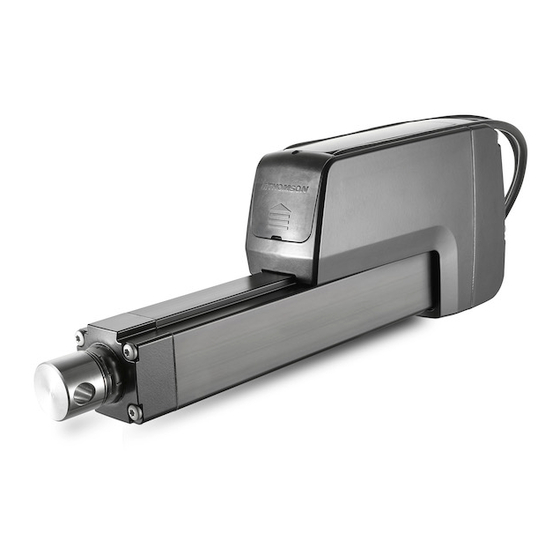
- Page 1 Thomson Electrak ® Electric Linear Actuator Installation Manual Edition 2016-01 P-264-HD www.thomsonlinear.com...
- Page 2 (12) months from date of delivery. The application of this product is the responsibility of the buyer and Thomson makes no representation or warranty as to the suitability of the product for any particular use or purpose. For a copy of the entire warranty for this product that is contained in our standard terms and conditions of sale, please go to http://www.thomsonlinear.com/website/com/...
-
Page 3: Table Of Contents
5.1 Introduction to CANBUS SAE J1939 ..............20 5.2 CANBUS SAE J1939 communications protocol ..........20 6. Technical specifications ................ 24 6.1 Technical data ...................... 24 6.2 Ordering key ......................25 Thomson Electrak HD Actuator - Installation Manual - 2016-01 ®... -
Page 4: General
1.4 Transport and storage The actuator may only be transported and stored in the original packaging supplied by Thomson. The temperature during transportation and storage must be between -40 to +85° C (-40 to +185° F). Avoid shocks to the package. If the package is damaged, check the actuator for visible damage and notify the carrier, and if appropriate also Thomson. -
Page 5: Safety
3. Standards 3.1 EC Declaration of incorporation of partly completed machinery We, Thomson Linear declare that this product corresponds with the International Standard ISO 13766:2006-05 2nd Edition (Earth Moving Machinery, Electromagnetic Compatibility). The directive (MD) 2006/42/EC annex 2.1.B, RoHSII directive 2011/65/EU, and that the standard EN ISO 12100:2010, Safety of machinery, have been applied. -
Page 6: Installation
If you need any assistance from Thomson, please provide the serial number, manufacturing date and the designation of the actuator(s) in question. You can also use the QR code on the label to directly access Electrak HD information on www.thomsonlinear.com. -
Page 7: Mechanical Installation
12.9 (0.508) 12.9 (0.508) 30 (1.18) 30 (1.18) 12.2 E9 (0.48) 12.8 (0.506) 12.2 E9 (0.48) 12.8 (0.506) M12 × 1.75 1/2-20 NF-2B 8.2 (0.323) 8.2 (0.323) 19 (0.748) 19 (0.748) Thomson Electrak HD Actuator - Installation Manual - 2016-01 ®... - Page 8 3. Make sure to put the cover plate back correctly and torque the screw to 1.2Nm (10.6 in-lb) to ensure that the actuator cover plate and connectors are properly sealed. Thomson Electrak HD Actuator - Installation Manual - 2016-01 ®...
- Page 9 2. Put the sensor (b) into one of the slots and and lock it at the desired position by turning the clamp screw 45 degrees (c). If the sensor is mounted in the immediate vicinity of magnetic components, the switching characteristics of the sensor may change. Thomson Electrak HD Actuator - Installation Manual - 2016-01 ®...
-
Page 10: Electrical Installation
Signal cable Power Lead Cross Sections Length of cable (L) Min. allowed cross section (X) 0 - 4 m 2.5 mm [AWG 14] 4 - 10 m 4 mm [AWG 12] Thomson Electrak HD Actuator - Installation Manual - 2016-01 ®... - Page 11 If using an AC powered power supply it must be sized to handle the inrush current (batteries typically have no problem delivering the inrush current). Also contacts, switches and relays must be sized appropriately to be able to handle the inrush current. Thomson Electrak HD Actuator - Installation Manual - 2016-01 ®...
-
Page 12: Control Options Installation And Operation
Electrak Monitoring Package + Low Level Signal Motor Switching + End of Stroke Indication Output 4.6.10 Electrak Monitoring Package + Low Level Signal Motor Switching + Analog Position Output 4.6.11 CAN Bus J1939 Control + Open Loop Speed Control 4.6.12 Thomson Electrak HD Actuator - Installation Manual - 2016-01 ®... - Page 13 Limit switch max. current [mA] white not used brown Limit switch max. power blue Fuse black Double pole double throw switch violet output fully retracted output fully extended orange common grey Thomson Electrak HD Actuator - Installation Manual - 2016-01 ®...
- Page 14 / max. 0.1 / 0.25 blue Encoder resolution [mm/pulse] black 0 Vdc HDxx-B026 0.154 HDxx-B045 0.092 violet HDxx-B068 0.068 orange not used HDxx-B100 0.040 grey Fuse Double pole double throw switch Thomson Electrak HD Actuator - Installation Manual - 2016-01 ®...
- Page 15 Double pole double throw switch 50 - 100 mm stroke 65.62 150 - 250 mm stroke 32.81 300 - 500 mm stroke 19.69 550 - 1000 mm stroke 9.84 Thomson Electrak HD Actuator - Installation Manual - 2016-01 ®...
- Page 16 / max. 0.1 / 0.25 Encoder resolution [mm/pulse] Fuse HDxx-B026 0.154 HDxx-B045 0.092 Double pole double throw switch HDxx-B068 0.068 HDxx-B100 0.040 Thomson Electrak HD Actuator - Installation Manual - 2016-01 ®...
- Page 17 Limit switch max. power not used blue Extend / retract input voltage [Vdc] 9 - 32 black output fully retracted Extend / retract input current [mA] 6 - 22 violet orange grey – Thomson Electrak HD Actuator - Installation Manual - 2016-01 ®...
- Page 18 300 - 500 mm stroke 19.69 550 - 1000 mm stroke 9.84 grey – Extend / retract input voltage [Vdc] 9 - 32 Extend / retract input current [mA] 6 - 22 Thomson Electrak HD Actuator - Installation Manual - 2016-01 ®...
- Page 19 (120 Ohm) should be placed in mating wire harness, see below. Please refer to section 5 for more communication details. CAN Bus device in actuator or other equipment Resistor Thomson Electrak HD Actuator - Installation Manual - 2016-01 ®...
-
Page 20: Canbus Information
255, Not available ECU Instance 0, First instance Manufacture Code 547, Thomson Linear LLC Identity Number 5.2.2 Address The Electrak HD uses a default address value of 19 (0x13). In applications where the default address is not available, there are three additional methods in choosing a new address. - Page 21 This signal can be used to define the next actuator movement message without starting the motor. When movement is required this bit can be changed to high (1) and motion will begin using the other parameter signals encoded in the ACM. Thomson Electrak HD Actuator - Installation Manual - 2016-01 ®...
- Page 22 This 2-bit signal is used to inform the user that the operational voltage is outside of allowable running parameters. Any motion already in progress will continue until completed, but additional movement request will not be allowed until the operational voltage returns within the normal operating range. Thomson Electrak HD Actuator - Installation Manual - 2016-01 ®...
- Page 23 To prevent possible additional damage motion is prohibited while this flag is set. 5.2.5.12 Factory use The remaining 18 bits of the Actuator Feedback Message are used for factory calibration use only and under normal operation will be returned with 0x00. Thomson Electrak HD Actuator - Installation Manual - 2016-01 ®...
-
Page 24: Technical Specifications
9.8 10.1 10.4 10.7 11.0 11.3 11.6 11.9 12.2 HDxx-B100 9.7 10.0 10.3 10.6 10.9 11.2 11.5 11.8 12.1 12.4 * Conversion factor for kilogram to pound: 1 kg = 2.204623 lbs Thomson Electrak HD Actuator - Installation Manual - 2016-01 ®... -
Page 25: Ordering Key
F = forked cross hole for ½ inch pin 0950 = 950 mm P = metric female thread 1000 = 1000 mm G = inch female thread 8. Adapter orientation S = standard M = 90 ° turned Thomson Electrak HD Actuator - Installation Manual - 2016-01 ®... - Page 26 Electrak_HD_Installation_Operation_MNEN-0003-02 | 20170726KB Specifications are subject to change without notice. It is the responsibility of the product user to determine the suitability of this product for a specific application. All trademarks property of their respective owners. ©2017 Thomson Industries, Inc.