Teledyne Lecroy HDO4000 Operator's Manual
High definition oscilloscopes
Hide thumbs
Also See for HDO4000:
- Getting started manual (48 pages) ,
- Operator's manual (120 pages) ,
- Operator's manual (119 pages)
Table of Contents
Advertisement
Quick Links
Advertisement
Table of Contents

Related Manuals for Teledyne Lecroy HDO4000


Summary of Contents for Teledyne Lecroy HDO4000
- Page 1 Operator's Manual HDO4000 / HDO4000A High Definition Oscilloscopes...
- Page 2 LeCroy, Inc. documentation for their own internal educational purposes. HDO and Teledyne LeCroy, Inc. are trademarks of Teledyne LeCroy, Inc., Inc. Other product or brand names are trademarks or requested trademarks of their respective holders. Information in this publication supersedes all earlier versions.
-
Page 3: Table Of Contents
Contents Safety Symbols Precautions Operating Environment Cooling Cleaning Power Oscilloscope Overview Front of Oscilloscope Side of Oscilloscope Back of Oscilloscope Front Panel Signal Interfaces Oscilloscope Set Up Powering On/Off Software Activation Connecting to Other Devices/Systems Language Selection Using MAUI Touch Screen OneTouch Help Working With Traces Zooming... - Page 4 HDO4000/HDO4000A High Definition Oscilloscopes Operator's Manual Math and Measure Cursors Measure Math Memory Analysis Tools WaveScan Pass/Fail Testing Saving Data (File Functions) Save Auto Save Recall LabNotebook Report Generator Share Print Email & Report Settings Using the File Browser Utilities...
- Page 5 Certifications EMC Compliance Safety Compliance Environmental Compliance ISO Certification Warranty Intellectual Property Windows License Agreement Index...
-
Page 6: About This Manual
Teledyne LeCroy About This Manual This manual covers the operation and maintenance of all instruments in the HDO4000 series. With the introduction of later versions of the 64-bit MAUI software, particularly version 8.3 and later, the graphical user interface on some instruments looked very different from what was offered on earlier instruments and included different touch screen capabilities. -
Page 7: Safety
Safety Safety To maintain the instrument in a correct and safe condition, observe generally accepted safety procedures in addition to the precautions specified in this section. The overall safety of any system incorporating this product is the responsibility of the assembler of the system. Symbols These symbols appear on the instrument or in documentation to alert you to important safety concerns: Caution of potential damage to instrument or Warning of potential bodily injury. -
Page 8: Operating Environment
HDO4000/HDO4000A High Definition Oscilloscopes Operator's Manual Operating Environment Temperature: 5 to 40° C. Humidity: Maximum relative humidity 90 % for temperatures up to 31° C, decreasing linearly to 50% relative humidity at 40° C. Altitude: Up to 3,000 m at or below 30° C. -
Page 9: Power
Safety Power AC Power The instrument operates from a single-phase, 100-240 Vrms (± 10%) AC power source at 50/60 Hz (± 5%) or a 100-120 Vrms (± 10%) AC power source at 400 Hz (± 5%). Manual voltage selection is not required because the instrument automatically adapts to the line voltage. - Page 10 HDO4000/HDO4000A High Definition Oscilloscopes Operator's Manual...
-
Page 11: Oscilloscope Overview
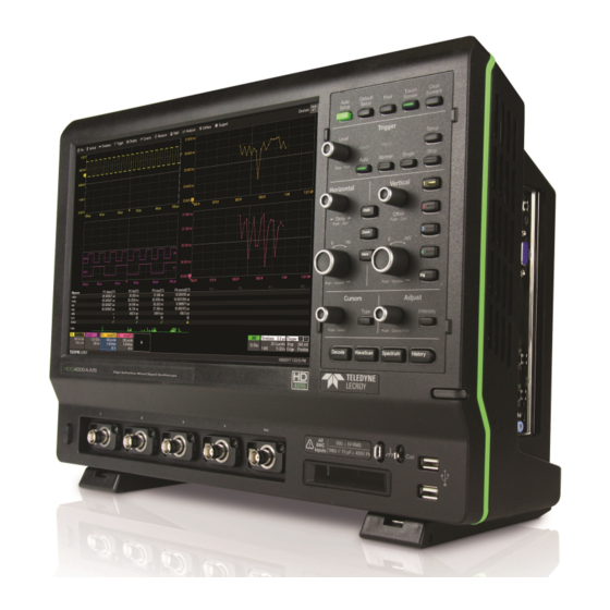
Oscilloscope Overview Oscilloscope Overview Front of Oscilloscope A. Touch screen display G. Mixed-Signal interface B. Front panel H. Ground and Calibration output terminals C. Stylus holder I. USB ports D. Power button J. Feet rotated back and tilted E. Channel inputs (C1-4) F. -
Page 12: Side Of Oscilloscope
HDO4000/HDO4000A High Definition Oscilloscopes Operator's Manual Side of Oscilloscope A. DVI, VGA, and HDMI ports for external monitor B. USB 2.0 ports (4) C. Ethernet ports (2) for connecting to LAN or remote control D. Audio In/Out (mic, speaker, and line-in) for connecting external audio devices E. -
Page 13: Back Of Oscilloscope
Oscilloscope Overview Back of Oscilloscope A. Built-in carrying handle B. Aux Out C. Ref In/Out for external reference clock D. USBTMC port for remote control E. AC power inlet... -
Page 14: Front Panel
HDO4000/HDO4000A High Definition Oscilloscopes Operator's Manual Front Panel Front panel controls duplicate functionality available through the touch screen and are described here only briefly. Knobs on the front panel function one way if turned and another if pushed like a button. The first label describes the knob’s “turn”... -
Page 15: Vertical Controls
Oscilloscope Overview Math, Zoom, and Mem(ory) Buttons The Zoom button creates a quick zoom for each open channel trace. Touch the zoom trace descriptor box to display the zoom controls. The Math and Mem(ory) buttons open the corresponding setup dialogs. If a Zoom, Math or Memory trace is active, the button illuminates to indicate that the Vertical and Horizontal knobs will now control that trace. -
Page 16: Miscellaneous Controls
HDO4000/HDO4000A High Definition Oscilloscopes Operator's Manual Miscellaneous Controls Auto Setup performs an Auto Setup. Default Setup restores the factory default configuration. Print captures the entire screen and outputs it according to your Print settings. It can also be configured to output a LabNotebook entry. -
Page 17: Signal Interfaces
Channel (Cx) dialog. System (probe plus instrument) gain settings are automatically calculated and displayed based on the probe attenuation. Probes The oscilloscope is compatible with the included passive probes and most Teledyne LeCroy ProBus active probes that are rated for the instrument’s bandwidth. Probe specifications and documentation are available at teledynelecroy.com/probes. - Page 18 HDO4000/HDO4000A High Definition Oscilloscopes Operator's Manual Digital Leadset The digital leadset provided with -MS model oscilloscopes enables input of up-to-16 lines of digital data. Lines can be organized into four logical groups and renamed appropriately. The digital leadset features two digital banks with...
-
Page 19: Oscilloscope Set Up
Registered users can receive an email notification when a new update is released. Follow the instructions on the website to download and install the software. Trial Options HDO4000 oscilloscopes are delivered with 30-day-trial licenses of some available software option packages. To activate a trial package: 1. Go to Utililties > Utilities Setup > Options. -
Page 20: Connecting To Other Devices/Systems
HDO4000/HDO4000A High Definition Oscilloscopes Operator's Manual Purchased Options If after your trial has ended you decide to purchase an option, you will receive a license key via email that activates the optional features. See Options for instructions on activating optional software packages. -
Page 21: Remote Control
Oscilloscope Set Up Connect the monitor cable to a video output on the side of the instrument (VGA, DVI-D, and HDMI are all supported). Go to Display > Display Setup > Open Monitor Control Panel to configure the display. Be sure to select the instrument as the primary monitor. -
Page 22: Language Selection
HDO4000/HDO4000A High Definition Oscilloscopes Operator's Manual Language Selection To change the language that appears on the touch screen: 1. Go to Utilities > Preference Setup > Preferences and make a Language selection. 2. Follow the prompt to restart the application. -
Page 23: Using Maui
Using MAUI Using MAUI MAUI, the Most Advanced User Interface, is Teledyne LeCroy's unique oscilloscope user interface. MAUI is designed for touch—all important controls for vertical, horizontal, and trigger are only one touch away. Touch Screen The touch screen is the principal viewing and control center. The entire display area is active: use your finger or a stylus to touch, drag, swipe, or draw a selection box. -
Page 24: Menu Bar
HDO4000/HDO4000A High Definition Oscilloscopes Operator's Manual Menu Bar The top of the window contains a complete menu of functions. Making a selection here changes the dialogs displayed at the bottom of the screen. While many common operations can also be performed from the front panel or launched via the descriptor boxes, the menu bar is the best way to access dialogs for Save/Recall (File) functions, Display functions, Status, LabNotebook, Pass/Fail setup, and Utilities/Preferences setup. -
Page 25: Grid Intensity
Using MAUI Grid Indicators These indicators appear around or on the grid to mark important points on the display. They are matched to the color of the trace to which they apply. When multiple traces appear on the same grid, indicators refer to the foreground trace—the one that appears on top of the others. -
Page 26: Descriptor Boxes
HDO4000/HDO4000A High Definition Oscilloscopes Operator's Manual Descriptor Boxes Trace descriptor boxes appear just beneath the grid whenever a trace is turned on. They function to: Inform—descriptors summarize the current trace settings and its activity status. Navigate—touch the descriptor box once to activate the trace, a second time to open the trace setup dialog. - Page 27 Using MAUI Other Trace Descriptor Boxes Similar descriptor boxes appear for math (Fx), zoom (Zx), and memory (Mx) traces. These descriptor boxes show any Horizontal scaling that differs from the signal timebase. Units will be automatically adjusted for the type of trace. Trace Context Menu Touch and hold ("right-click") on the trace descriptor box until a white circle appears to open the trace context menu, a pop-up menu of actions to apply to the trace such as turn off, move to next grid or label.
- Page 28 HDO4000/HDO4000A High Definition Oscilloscopes Operator's Manual Dialogs Dialogs appear at the bottom of the display for entering setup data. The top dialog will be the main entry point for the selected functionality. For convenience, related dialogs appear as a series of tabs behind the main dialog.
-
Page 29: Message Bar
Using MAUI Message Bar At the bottom of the oscilloscope display is a narrow message bar. The current date and time are displayed at the far right. Status, error, or other messages are also shown at the far left, where "Teledyne LeCroy"... -
Page 30: Onetouch Help
HDO4000/HDO4000A High Definition Oscilloscopes Operator's Manual OneTouch Help Touch, drag, swipe, pinch, and flick can be used to create and change setups with one touch. Just as you change the display by using the setup dialogs, you can change the setups by moving different display objects. - Page 31 Using MAUI Copy Setups To copy the setup of one trace to another of the same type (e.g., channel to channel, math to math), drag-and-drop the source descriptor box onto the target descriptor box. To copy the setup of a measurement (Px), drag-and-drop the source column onto the target column of the Measure table.
- Page 32 HDO4000/HDO4000A High Definition Oscilloscopes Operator's Manual Position Cursors To change cursor measurement time/level, drag cursor markers to new positions on the grid. The cursor readout will update immediately. To place horizontal cursors on zooms or other calculated traces where the source Horizontal Scale has forced cursors off the grid, drag the cursor readout from below the Timebase descriptor to the grid where you wish to place the cursors.
- Page 33 Using MAUI Store to Memory To store a trace to internal memory, drag-and-drop its trace descriptor box onto the target memory (Mx) descriptor box. Move Trace To move a trace to a different grid, drag-and-drop the trace descriptor box onto the target grid. Scroll To scroll long lists of values or readout tables, swipe the selection dialog or table in an up or down direction.
- Page 34 HDO4000/HDO4000A High Definition Oscilloscopes Operator's Manual Pan Trace To pan a trace, activate it to bring it to the forefront, then drag the waveform trace right/left or up/down. If it is the source of any other trace, that trace will move, as well. For channel traces, the Timebase descriptor box will show the new Horizontal Delay value.
- Page 35 Using MAUI Zoom To create a new zoom trace, touch then drag diagonally to draw a selection box around the portion of the trace you want to zoom. Touch the Zx descriptor box to open the zoom factor controls and adjust the zoom exactly.
- Page 36 HDO4000/HDO4000A High Definition Oscilloscopes Operator's Manual Turn Off To turn off a trace, flick the trace descriptor box toward the bottom of the screen.
-
Page 37: Working With Traces
Using MAUI Working With Traces Traces are the visible representations of waveforms that appear on the display grid. They may show live inputs (Cx, Digitalx), a math function applied to a waveform (Fx), a stored memory of a waveform (Mx), a zoom of a waveform (Zx), or the processing results of special analysis software. - Page 38 HDO4000/HDO4000A High Definition Oscilloscopes Operator's Manual Turning On/Off Traces Analog Traces From the front panel, press the Channel button (1-4) to turn on the trace; press again to turn it off. To turn on the trace from the touch screen, touch the Add New box and select Channel, or drag another Channel (Cx) descriptor box to the Add New box.
- Page 39 Using MAUI To use the virtual keypad, touch the soft keys exactly as you would a calculator. When you touch OK, the calculated value is entered in the field. Moving Traces Use any of these methods to move traces from grid to grid. See OneTouch Help for ways to pan traces within the same grid.
- Page 40 HDO4000/HDO4000A High Definition Oscilloscopes Operator's Manual Labeling Traces The Label function gives you the ability to add custom annotations to the trace display. Once placed, labels can be moved to new positions or hidden while remaining associated with the trace.
-
Page 41: Zooming
Using MAUI Zooming Zooms magnify a selected region of a trace by altering the Horizontal Scale relative to the source trace. Zooms may be created in several ways, using either the front panel or the touch screen. You can adjust zooms the same as any other trace using the front panel Vertical and Horizontal knobs or the touch screen zoom factor controls. -
Page 42: Creating Zooms
HDO4000/HDO4000A High Definition Oscilloscopes Operator's Manual Creating Zooms Any type of trace can be "zoomed" by creating a new zoom trace (Zx) following the procedures here. Note: On instruments with OneTouch, traces can be "zoomed" by pinching/unpinching two fingers over the trace, but this method does not create a separate zoom trace. With channel traces, pinching will alter the acquisition timebase and the scale of all traces. -
Page 43: Print/Screen Capture
Using MAUI Adjust Zoom Scale The zoom's Horizontal units will differ from the signal timebase because the zoom is showing a calculated scale, not a measured level. This allows you to adjust the zoom factor using the front panel knobs or the zoom factor controls however you like without affecting the timebase (a characteristic shared with math and memory traces). - Page 44 HDO4000/HDO4000A High Definition Oscilloscopes Operator's Manual...
-
Page 45: Acquisition
Acquisition Acquisition The acquisition settings include everything required to produce a visible trace on screen and an acquisition record that may be saved for later processing and analysis: Vertical axis scale at which to show the input signal and probe characteristics that affect the signal, such as attenuation and deskew time Horizontal axis scale at which to represent time, and acquisition sampling mode and sampling rate... -
Page 46: Viewing Status
HDO4000/HDO4000A High Definition Oscilloscopes Operator's Manual Viewing Status All instrument settings can be viewed through the various Status dialogs. These show all existing acquisition, trigger, channel, math function, measurement and parameter configurations, as well as which are currently active. Access the Status dialogs by choosing the Status option from the Vertical, Timebase, Math, or Analysis menus (e.g., Channel Status, Acquisition Status). - Page 47 Vertical settings for scale, offset, coupling, bandwidth, and probe attenuation Rescale settings Pre-processing settings for pre-acquisition processes such as noise filtering and interpolation. If a Teledyne LeCroy probe is connected, its Probe dialog appears to the right of the Cx dialog.
- Page 48 On legacy HDO4000 models, Interpolate applies either Linear or (Sinx)/x interpolation to the waveform. Linear inserts a straight line between sample points and is best used to reconstruct straight-edged signals such as square waves.
-
Page 49: Probe Dialog
Auto Zero corrects for DC offset drifts that naturally occur from thermal effects in the amplifier of active probes. Teledyne LeCroy probes incorporate Auto Zero capability to remove the DC offset from the probe's amplifier output to improve the measurement accuracy. -
Page 50: Digital (Mixed Signal)
HDO4000/HDO4000A High Definition Oscilloscopes Operator's Manual Digital (Mixed Signal) digital leadset (standard with -MS model oscilloscopes) inputs up-to-16 lines of digital data. Leads are organized into two banks of eight leads each, and you assign each bank a standard Logic Family or a custom Threshold to define the digital logic of the signal. - Page 51 Acquisition Digitalx (Group) Set Up To set up a digital input: 1. Connect the digital leadset to the test device and the instrument. 2. From the menu bar, choose Vertical > Digital <#> Setup, or press the front panel Dig button and select the desired Digitalx tab.
-
Page 52: Digital Display Set Up
HDO4000/HDO4000A High Definition Oscilloscopes Operator's Manual Digital Display Set Up Choose the type and position of the digital traces that appear on screen for each digital group. Set up the digital group. 2. Choose a Display Mode: Lines (default) shows a time-correlated trace indicating high, low, and transitioning points (relative to the Threshold) for every digital line in the group. -
Page 53: Renaming Digital Lines
Acquisition Renaming Digital Lines The labels used to name each line can be changed to make the user interface more intuitive. Also, labels can be "swapped" between lines. Changing Labels Set up the digital group. 2. Touch Label and select from: Data - the default, which appends "D."... -
Page 54: Timebase
HDO4000/HDO4000A High Definition Oscilloscopes Operator's Manual Timebase Timebase, also known as Horizontal, settings control the trace along the X axis. The timebase is shared by all channels. The time represented by each horizontal division of the grid, or Time/Division, is most easily adjusted using the front panel Horizontal knob. - Page 55 Acquisition Real Time Memory Max. Sample Points is the maximum number of samples taken per acquisition. The actual number of samples acquired can be lower due to the current Sample Rate and Time/Division settings. The instrument allocates memory as needed to maintain the highest sample rate possible for the timebase.
-
Page 56: Sampling Modes
HDO4000/HDO4000A High Definition Oscilloscopes Operator's Manual Sampling Modes The Sampling Mode determines how the instrument samples the input signal and renders it for display. Real Time Sampling Mode Real Time sampling mode is a series of digitized voltage values sampled on the input signal at a uniform rate. - Page 57 Acquisition Sequence Sampling Mode In Sequence Mode sampling, the completed waveform consists of a number of fixed-size segments. The instrument uses the Timebase Sequence settings to determine the capture duration of each segment. The desired number of segments, maximum segment length, and total available memory are used to determine the actual number of samples or segments, and time or points.
- Page 58 HDO4000/HDO4000A High Definition Oscilloscopes Operator's Manual Channel descriptor boxes indicate the total number of segments acquired in sequence mode. Zoom descriptor boxes show the first segment displayed and total number of segments displayed ([#] #). As with all other zoom traces, the zoomed segments are highlighted on the source trace.
-
Page 59: History Mode
Acquisition History Mode History Mode allows you to review any acquisition saved in the history buffer, which automatically stores all acquisition records until full. Not only can individual acquisitions be restored to the grid, you can "scroll" backward and forward through the history at varying speeds to capture individual details or changes in the waveforms over time. - Page 60 HDO4000/HDO4000A High Definition Oscilloscopes Operator's Manual Replay Acquisition History This is a good way to begin using History Mode. Watching a "movie" of the history allows you to see waveform changes that are invisible during real-time acquisition. Select View History to enable the display, then use the Navigation buttons or the slider bar at the bottom of the dialog to "scroll"...
-
Page 61: Trigger
Acquisition Trigger Triggers define the event around which digitized information is displayed on the grid. Different Trigger Types are used to select different events in the trigger source waveforms: edge voltages, pulse widths, high/low states, etc. These may be a single channel event or a complex pattern of events across several channels. -
Page 62: Trigger Types
A event, then triggers on the B event. In Normal trigger mode, it automatically resets after the B event, and re-arms upon the next matching A event. Note: This functionality is identical to Teledyne LeCroy's previous Qualify and State triggers, but presented through a different user interface. Smart Triggers Smart triggers allow you to apply Boolean logic conditions to the basic signal characteristics of level, slope, and polarity to determine when to trigger. - Page 63 Acquisition Runt triggers when a pulse crosses a first threshold, but fails to cross a second threshold before re- crossing the first. Other defining conditions for this trigger are the edge (triggers on the slope opposite to that selected) and runt width. SlewRate triggers when the rising or falling edge of a pulse crosses an upper and a lower level.
- Page 64 HDO4000/HDO4000A High Definition Oscilloscopes Operator's Manual Slope/Polarity For some triggers, such as Edge, you will be asked to select the waveform Slope (rising vs. falling) on which the triggering event may occur. For others, such as Width, the equivalent selection will be Polarity (positive vs. negative).
- Page 65 Acquisition 1. On the Trigger dialog, select Pattern trigger type. Open the Digital Pattern dialog. 2. At the far right of the dialog, choose either Logic Bus or Logic. 3. Optionally, deselect Filter Out Unstable Conditions. This default filter ignores short glitches in logic state triggers that last less than 3.5 ns.
- Page 66 HDO4000/HDO4000A High Definition Oscilloscopes Operator's Manual Analog Pattern Tip: With the Mixed-Signal option, you can also use the Digital Pattern dialog to set an analog state pattern. Touch Set All To... and select Don't Care. This will eliminate any meaningful digital pattern and activate all the Boolean operators.
- Page 67 Acquisition Serial Trigger The Serial trigger type will appear if you have installed serial data trigger and decode options. Select the Serial type then the desired Protocol to open the serial trigger setup dialogs. For setup instructions, see the software instruction manual at teledynelecroy.com/support/techlib under Manuals >...
-
Page 68: Trigger Holdoff
HDO4000/HDO4000A High Definition Oscilloscopes Operator's Manual Trigger Holdoff Holdoff is either a period of time or an event count that may be set as an additional condition for Edge and Pattern triggers. Holdoff disables the trigger temporarily, even if the other conditions are met. Use Holdoff to obtain a stable trigger for repetitive, composite waveforms. - Page 69 Acquisition Note: Because there is only one trigger per acquisition, the trigger event will always belongs to the new acquisition. The processing time shown here is for purposes of illustration only. Regardless of where in the acquisition record the trigger event was found (first edge or last), the display will show time pre- and post-trigger based on your Time/Div and Delay settings.
- Page 70 HDO4000/HDO4000A High Definition Oscilloscopes Operator's Manual Holdoff Set Up To add Holdoff to an Edge or Pattern trigger, touch the Trigger descriptor box or press the front panel Trigger Setup button, then open the Holdoff tab. Choose to Holdoff by Time (the clock) or Events.
-
Page 71: Display
Display Display Display settings affect the number and style of grids that appear on screen and some of the visual characteristics of traces, such as persistence. HDO oscilloscopes feature multi-grid display, where each separate grid represents the full number of 4096 vertical levels. -
Page 72: Display Set Up
HDO4000/HDO4000A High Definition Oscilloscopes Operator's Manual Display Set Up To access the Display dialog, choose Display > Display Setup. Note: The "Extend Grids..." option only appears when a second monitor is connected. Minimize the oscilloscope window and use the standard Windows Display controls to make the instrument the primary display. - Page 73 Display Axis labels display the values represented by each division of the grid, based on your vertical scale and timebase. Turned on by default, they may appear as absolute values or delta from center (0). Deselect the checkbox to remove them from the display. Trace Intensity Choose a line style for traces: solid Line or disconnected sample Points.
-
Page 74: Persistence Display
HDO4000/HDO4000A High Definition Oscilloscopes Operator's Manual Persistence Display The Persistence feature retains waveform traces on the display for a set amount of time before allowing them to gradually "decay," similar to the analog-style display of old, phosphor screen oscilloscopes. The display is generated by repeated sampling of events over time and the accumulation of the sampled data into "persistence maps". - Page 75 Display percentage causes the pixels to be saturated at a lower population and makes visible those events rarely seen at higher saturation levels. 4. In Persistence Time, enter the duration of time (in seconds) after which persistence data is erased from the display.
- Page 76 HDO4000/HDO4000A High Definition Oscilloscopes Operator's Manual...
-
Page 77: Math And Measure
Math and Measure Math and Measure Teledyne LeCroy offers a rich set of standard, pre-programmed tools for the "quickest time to insight" into the characteristics of acquired waveforms. Most instruments calculate measurements for all samples in an acquisition, enabling you to rapidly and thoroughly calculate thousands or millions of parameter values and apply a variety of mathematical functions to the input waveform trace. -
Page 78: Cursor Types
HDO4000/HDO4000A High Definition Oscilloscopes Operator's Manual Cursor Types These cursors can be placed on most Channel, Memory, Math or Zoom traces: Horizontal (Time) cursors intersect two points on the horizontal axis. The readout shows absolute values and a delta of the two points. - Page 79 Math and Measure Standard Cursors Dialog These controls can be used instead of the front panel controls to set cursors or to refine the cursor position. Access the dialog by choosing Cursors > Cursors Setup from the menu bar. Cursor Type buttons select the type of cursor displayed on the grid.
-
Page 80: Measure
HDO4000/HDO4000A High Definition Oscilloscopes Operator's Manual Measure Measurement parameters are tools that give you access to a wide range of waveform properties. Use them to analyze many attributes of your waveform such as rise-time, rms voltage, and peak-to-peak voltage. Measurements can also be graphed as a trend for statistical analysis. - Page 81 Math and Measure Parameter Set Up The Measure Dialog gives quick access to measurement features. Besides configuring parameters, use the Measure dialog to show Statistics and Histicons, or to Gate measurements. You can also plot the measurement results as a Trend.
- Page 82 HDO4000/HDO4000A High Definition Oscilloscopes Operator's Manual Gating Measurements By using gates, you can narrow the span of the waveform on which to perform tests and measurements, allowing you to focus on the area of greatest interest. For example, if you "gate" five rising edges of the waveform, rise time calculations are performed only on the five pulses bounded by the gate posts.
- Page 83 Math and Measure List of Standard Measurements Measurements included standard with the oscilloscope are listed below alphabetically. Note: There may be additional parameters available depending on the software options installed on the oscilloscope. Measurement Description Measures the difference between upper and lower levels in two-level signals. Differs from pkpk Amplitude in that noise, overshoot, undershoot, and ringing do not affect the measurement.
- Page 84 HDO4000/HDO4000A High Definition Oscilloscopes Operator's Manual Measurement Description Average of data for time domain waveform. Computed as centroid of distribution for a histogram Mean of the data values. Minimum Measures the lowest point in a waveform. Unlike base, does not assume waveform has two (min) levels.
- Page 85 Math and Measure Measurement Description Higher of two most probable states (base is lower). Measures higher level in two-level signals. Differs from max in that noise, overshoot, undershoot, and ringing do not affect measurement. On signals not having two major levels (such as triangle or saw-tooth waves), the amplitude parameter returns the same value as minimum.
-
Page 86: Calculating Measurements
HDO4000/HDO4000A High Definition Oscilloscopes Operator's Manual Calculating Measurements The instrument uses the following methods to calculate measurements. Determining Top and Base Lines Proper determination of the top and base reference lines is fundamental for ensuring correct parameter calculations. The analysis begins by computing a histogram of the waveform data over the time interval spanned by the left and right measurement gates. - Page 87 Math and Measure Determining Time Parameters Time parameter measurements such as width, period and delay are carried out with respect to the mesial reference level, located halfway (50%) between the top and base reference lines or with respect to the specified level for @level parameters.
-
Page 88: Math
HDO4000/HDO4000A High Definition Oscilloscopes Operator's Manual Math Math traces (Fx) display the result of applying a mathematical operation to a source trace. The output of a math function is always another trace, whereas the output of a measurement parameter is a tabular readout of the measurement. - Page 89 Math and Measure 4. In Operator1, choose the math operation to perform. 5. The choice of operator drives the number of Source fields you will see displayed. Make a selection in each field, or drag the source channel descriptor box to the field. A Summary of the function you are building appears on the dialog.
- Page 90 HDO4000/HDO4000A High Definition Oscilloscopes Operator's Manual Average Function Setting Up Averaging To apply Continuous or Summed Averaging as a Math function: 1. Follow the usual steps to set up a math fuction, selecting Average from the Basic Math submenu. 2. On the Average subdialog, choose Summed or Continuous.
- Page 91 Math and Measure However, by setting a Sweeps value, you establish a fixed weight that is assigned to the old average once the number of sweeps is reached. For example, for a sweeps (weight) value of 4: Sweep New Average = 1 (no old average yet) (new data +0 * old average)/(0 + 1) = new data only (new data + 1*old average)/(1 + 1) = 1/2 new data +1/2 old average...
- Page 92 HDO4000/HDO4000A High Definition Oscilloscopes Operator's Manual ERes Function ERes (Enhanced Resolution) filtering increases vertical resolution, allowing you to distinguish closely spaced voltage levels. The instrument's ERes function is similar to smoothing the signal with a simple, moving-average filter. However, it is more efficient concerning bandwidth and pass-band filtering.
- Page 93 Math and Measure Resolution -3 dB Bandwidth (x Filter Length increased by Nyquist) (Samples) 0.241 0.121 0.058 0.029 0.016 With low-pass filters, the actual SNR increase obtained in any particular situation depends on the power spectral density of the noise on the signal. The improvement in SNR corresponds to the improvement in resolution if the noise in the signal is white (evenly distributed across the frequency spectrum).
- Page 94 HDO4000/HDO4000A High Definition Oscilloscopes Operator's Manual FFT Function For a large class of signals, you can gain greater insight by looking at spectral representation rather than time description. Signals encountered in the frequency response of amplifiers, oscillator phase noise and those in mechanical vibration analysis, for example, are easier to observe in the frequency domain.
- Page 95 Math and Measure Window Type Applications and Limitations Rectangular Normally used when the signal is transient (completely contained in the time-domain window) or known to have a fundamental frequency component that is an integer multiple of the fun- damental frequency of the window. Signals other than these types will show varying amounts of spectral leakage and scallop loss, which can be corrected by selecting another type of window.
- Page 96 HDO4000/HDO4000A High Definition Oscilloscopes Operator's Manual Rescale Function and Assigning Units The Rescale function allows you to apply a multiplication factor (a) and additive constant (b) to any source waveform. You can do it in the unit of your choice, depending on the type of application.
- Page 97 Math and Measure Abbreviated Units of Measure Abbreviation Measure Abbreviation Measure (blank) No units Newton Ampere Coulomb Pascal CYCLE Cycles Percent Decibel POISE Poise Decibel referred to carrier Parts per million Decibel Milliwatt Radian Decibel Volts Degree (of arc) DBUZ Decibel Microamp Minute (of arc) Decade...
- Page 98 HDO4000/HDO4000A High Definition Oscilloscopes Operator's Manual List of Standard Operators The math operators included standard with your oscilloscope are listed below alphabetically. Note: There may be additional operators available depending on the software options installed on the oscilloscope. Operator Definition Absolute For every point in the waveform the distance away from zero is calculated.
- Page 99 Math and Measure Operator Definition For every point in the waveform, the value of Source1 is added to the value of Source 2. Source1 and Source2 must have the same horizontal units and scale and the same vertical units. Trend Produces a waveform composed of a series of parameter measurements in the order the meas- urements were taken.
-
Page 100: Memory
Save (External) Waveform Files to Memory Trace (.trc) files saved on other Teledyne LeCroy instruments can also be saved to internal memory. Use the Recall Waveform function to save external files to memory. Then, you can use the Memories dialog restore them to the touch screen. - Page 101 Math and Measure Restoring Memories The Memories dialog is a convenient panel for restoring saved memories to the display. Access the Memories dialog by pressing the front panel Mem button or choosing Math > Memory Setup. Check On next to the memory trace you wish to display. A description of the memory showing the source channel and creation time appears next to each Mx on the dialog.
-
Page 102: Analysis Tools
HDO4000/HDO4000A High Definition Oscilloscopes Operator's Manual Analysis Tools The Analysis menu tools complement the standard math and measurements to help you understand the behavior of waveforms. WaveScan searches single or multiple acquisitions for events that meet specific criteria. Pass/Fail Testing shows whether waveforms meet mask test limits. - Page 103 Analysis Tools Setting Up WaveScan This procedure explains how to set up WaveScan to search an acquisition for events of interest. Set up your source channel and triggers before setting up the scan. 1. Press the front panel Stop button to stop acquisition. 2.
- Page 104 HDO4000/HDO4000A High Definition Oscilloscopes Operator's Manual Non-monotonic Mode Non-monotonic Mode looks for edges that cross a threshold more than once between high and low levels. All events that meet the criteria of slope, hysteresis, and level are presented in a table and highlighted in the source trace.
- Page 105 Analysis Tools Serial Pattern Mode Serial Pattern Mode is used for finding 2- to 64-bit patterns in digital sequences; ideal for bursted patterns where a PLL cannot lock. Serial Pattern Mode settings are: Viewing. Choose to enter the pattern as Binary or Hex(adecimal). Binary/Hex.
- Page 106 HDO4000/HDO4000A High Definition Oscilloscopes Operator's Manual WaveScan Search Search is used to find events in traces—usually zoom (Zx) traces—that match user-defined criteria. To search within WaveScan: 1. Select the Zoom view. 2. After stopping the acquisition, open the Zx dialog that appears behind the WaveScan dialog.
-
Page 107: Pass/Fail Testing
Analysis Tools Pass/Fail Testing Pass/Fail testing is a type of mask testing that is particularly useful for comparing newly acquired signals to a previously acquired "golden standard" waveform. Mask Testing A mask defines an area of the grid against which a source Channel, Zoom, or Math trace is compared. Test conditions are associated with the mask, defining how the waveform is to be compared to the masked area (e.g., some/all values fall within, some/all values fall outside), and a pass or fail result is returned indicating the condition was found to be true or false. - Page 108 HDO4000/HDO4000A High Definition Oscilloscopes Operator's Manual Remove a Mask from the Display Touch the Delete button on the Load Mask subdialog. Set Gates Set gates to limit the portion of the waveform that is compared to the mask. 1. Open the Gate subdialog.
-
Page 109: Saving Data (File Functions)
Note: Only files saved in Teledyne LeCroy binary format (.TRC) can be recalled to the display. Save Waveform To Memory 1. From the menu bar, choose File > Save Waveform. - Page 110 All Displayed button. 4. Select a file Format: Binary, Teledyne LeCroy's binary file format (.trc). Binary results in the smallest possible file size, and is necessary for recalling waveforms to Teledyne LeCroy instruments. Binary files can be converted to ASCII using Teledye LeCroy utilities such as WaveStudio.
-
Page 111: Save Setup
Saving Data (File Functions) Browse and use the File Browser. By default, trace files are saved to the D:\Waveforms folder on the instrument hard drive. 7. If you do not want to use the Source prefix or Counter number, deselect them. 8. - Page 112 HDO4000/HDO4000A High Definition Oscilloscopes Operator's Manual Save Table The Save Table function saves tabular measurement data displayed on screen to an Excel or ASCII file. 1. From the menu bar, choose File > Save, then choose Table. 2. To save only one of the tables displayed, touch Source and navigate to the selection.
- Page 113 Saving Data (File Functions) Save Screen Image The full touch screen display or selected portions of it can be captured, saved to an image file, and marked with custom annotations. 1. From the menu bar, choose File > Save, then choose Screen Image. 2.
-
Page 114: Auto Save
HDO4000/HDO4000A High Definition Oscilloscopes Operator's Manual Auto Save Data that appears on the oscilloscope display, such as waveforms, measurement readouts and decoder data, can be very dynamic and difficult to read from the oscilloscope unless you stop the acquisition. Auto Save enables you to automatically store waveform and table data to file with each new trigger. The file can later be recalled to the oscilloscope or saved permanently to external storage. -
Page 115: Recall
Saving Data (File Functions) Recall Setups saved to internal memory or to .LSS file can be recalled to restore the oscilloscope to the saved state. Waveform data stored to .TRC files can be recalled into a memory and from there restored to the screen. To recall and modify saved LabNotebook files, see Recall LabNotebook. -
Page 116: Recall Setup
HDO4000/HDO4000A High Definition Oscilloscopes Operator's Manual Recall Setup Choose File > Recall Setup... from the menu bar. Recall Setup from Memory 1. Choose to Recall From Memory. 2. Touch one of the six Recall buttons under Recall From Internal Setup.. -
Page 117: Labnotebook
Saving Data (File Functions) LabNotebook The LabNotebook feature allows you to create and save composite files containing a screen capture of all displayed waveforms, as well as all waveform and setup data at the time of capture. LabNotebooks can be output to a preformatted .PDF, .RTF, or .HTML report. You can also upload your own report layout if you prefer not to use the default. -
Page 118: Labnotebook Drawing Toolbar
HDO4000/HDO4000A High Definition Oscilloscopes Operator's Manual Browse and use the File Browser to make a selection. By default, LabNotebook files are saved to the D:\LabNotebook folder on the instrument hard drive. Note: Changing the file path, name, or format will cause the counter to reset to the next number in that sequence. - Page 119 Saving Data (File Functions) Tool Function More Activates a Custom line color field. The default color is Yellow. To choose another, touch the color swatch, then select from the Color dialog. You can enter RGB values, or choose from the spectrum. After saving, the new color appears in the Custom field.
- Page 120 HDO4000/HDO4000A High Definition Oscilloscopes Operator's Manual Recall and Preview 1. Enter the path to the file in LabNotebook Entry, or touch Browse and navigate to the file. 2. Touch View On/Off to open it in the Preview window. 3. While the file is in preview, you may...
- Page 121 Saving Data (File Functions) Manage Attachments To append external files to the LabNotebook composite (such as images of the DUT, mask files, test scripts, or anything relevant to the entry): 1. Browse to and select the LabNotebook Entry. If the file is in the Selected Folder, just use the Up/Down Arrow keys to select it.
-
Page 122: Report Generator
HDO4000/HDO4000A High Definition Oscilloscopes Operator's Manual Report Generator The Report Generator feature allows you to output a preformatted report consisting of an annotated screen image and a summary of the setups in place when it was captured. The report can be sourced from an existing LabNotebook, or it can be newly generated from the current state of the oscilloscope. -
Page 123: Share
Saving Data (File Functions) From Current State If you are creating a report from the current state of the instrument, the procedure is much like that above, except that you will also be able to enter a new Description, Annotate Screen Image, and select your capture Area/Color Preferences as you would normally do when first creating a LabNotebook. -
Page 124: Print
HDO4000/HDO4000A High Definition Oscilloscopes Operator's Manual Print Print dialog settings control how the front panel Print button behaves. Print captures an image of the touch screen display, but there are several options as to what it does next with the image:... -
Page 125: Email & Report Settings
Saving Data (File Functions) Email & Report Settings This dialog contains additional settings used by the File Sharing and Report Generator functions. Email Settings 1. Select to use MAPI or SMTP. 2. If you chose SMTP, touch SMTP Server and enter the network address of your mail server. 3. -
Page 126: Using The File Browser
HDO4000/HDO4000A High Definition Oscilloscopes Operator's Manual Using the File Browser Selecting Browse on any of the File menu dialogs opens a File Browser that enables you to perform basic disk utility functions, as well as making file path/name and format selections. The additional file actions available depend on the actions available on the underlying dialog (Save file, Email report, etc.). - Page 127 Saving Data (File Functions) Auto Naming Selections The checkboxes to turn on/off the Source prefix and the Counter number suffix used to autogenerate file names will appear on the File Browser. These selections are linked to those on the underlying dialog, and changing the value in either place causes it to change everywhere.
- Page 128 HDO4000/HDO4000A High Definition Oscilloscopes Operator's Manual...
-
Page 129: Utilities
The Service button to the far right of the dialog launches a section of the application reserved for qualified Teledyne LeCroy service personnel. An access code is required to enter this section. Status The Utilities Status dialog displays information about your instrument including model number, serial number, firmware version, and installed hardware and software options. -
Page 130: Remote Control
The Remote dialog contains settings to configure remote control of the instrument and also network access. Supported remote control protocols are: TCPIP (Ethernet). If you choose this option, also install Teledyne LeCroy's VICP drivers on the controller. These are included in the VICP Passport plug-in, available free from teledynelecroy.com/support/softwaredownload... - Page 131 Utilities Configure the Remote Control Assistant Event Log The Remote Control Assistant monitors communication between the controller and instrument. You can log all events or errors only. The log can be output to an ASCII file and is invaluable when you are creating and debugging remote control programs.
-
Page 132: Auxiliary Output
HDO4000/HDO4000A High Definition Oscilloscopes Operator's Manual Auxiliary Output Use the Aux Output dialog to configure the output of the Aux Out port and Cal Out port. Auxiliary Output The Aux Out port outputs a 3.3 V CMOS into high impedance pulse following the selected event. -
Page 133: Date/Time
Utilities Date/Time Date/Time settings control the instrument's timestamp. These numbers appear in the message bar and on tables/records internal to the oscilloscope application, such as History Mode and WaveScan. To access the Date/Time dialog, choose Utilities > Utilities Setup from the menu bar, then touch the Date/Time tab. -
Page 134: Options
HDO4000/HDO4000A High Definition Oscilloscopes Operator's Manual Options Many optional software packages are available to extend the Analysis functions of the instrument. When you purchase an option, you will receive a key code by email that activates the new functionality. Use the Options dialog to activate software options by installing the key code. -
Page 135: Disk Utilities
Utilities Disk Utilities Use the Disk Utilities dialog to manage files and folders on your instrument's hard drive. Disk Space information is shown at the far right of the dialog for convenience. Note: These tasks can also be accomplished using the standard Microsoft Windows file management tools. -
Page 136: Preferences Settings
HDO4000/HDO4000A High Definition Oscilloscopes Operator's Manual Preferences Settings Preference settings have mostly to do with the appearance and performance of the instrument itself, rather than its interaction with other devices/systems. These setting are also called "non-volatile," because they are not lost and do not change when the oscilloscope is restarted or a setup panel is recalled. -
Page 137: Calibration
Utilities Calibration Calibration ensures that the output from the analog-to-digital converters (ADCs) accurately represents the input. The instrument is calibrated at the factory prior to shipment. So that it maintains specified performance, it is factory set to perform an automatic calibration routine upon start-up and whenever conditions warrant it. -
Page 138: Acquisition
HDO4000/HDO4000A High Definition Oscilloscopes Operator's Manual Acquisition The Acquisition preference settings determine how traces behave as Vertical Offset or Horizontal Delay changes. To access them, choose Utilities > Preference Setup and open the Acquisition dialog. Offset Setting constant in: Volts moves the Vertical Offset level indicator with the actual voltage level. -
Page 139: Color
Utilities Color Color dialog settings assign the colors used for channel, math, and memory traces. All dialogs, tables, and trace descriptor boxes will match the color of the trace assigned here. You can choose different colors to be used on the instrument and in print. For convenience, you can Preview print colors to see how the settings will appear in print output. -
Page 140: Miscellaneous
Miscellaneous These other Preference settings are located on the Miscellaneous dialog. To add the Teledyne LeCroy logo to print output, check Print Teledyne LeCroy Logo When Printing Grid Area Only. This identifies the instrument as the source of the image. -
Page 141: Maintenance
Maintenance Maintenance Topics in this section describe procedures for keeping the instrument in optimal working condition. Touch Screen Calibration Periodically calibrate the touch screen to maintain its accuracy and responsiveness. We recommend that you use a stylus rather than your finger for this procedure. 1. -
Page 142: Firmware Update
HDO4000/HDO4000A High Definition Oscilloscopes Operator's Manual Firmware Update Teledyne LeCroy frequently releases free oscilloscope firmware updates containing new product features and bug fixes. The installer updates multiple components including the base application, required DLLs, drivers, and low-level microcode for integrated circuits. -
Page 143: Technical Support
Resources Teledyne LeCroy publishes a free Technical Library on its website. Manuals, tutorials, application notes, white papers, and videos are available to help you get the most out of your Teledyne LeCroy products. Visit: teledynelecroy.com/support/techlib The Datasheet published on the product page contains the detailed product specifications. -
Page 144: Returning A Product For Service
4. Pack the product case in a cardboard shipping box with adequate padding to avoid damage in transit. 5. Mark the outside of the box with the shipping address given to you by Teledyne LeCroy; be sure to add the following: ATTN: <RMA code assigned by Teledyne LeCroy>... -
Page 145: Certifications
Certifications Certifications Teledyne LeCroy certifies compliance to the following standards as of the time of publication. See the EC Declaration of Conformity document shipped with your product for the current certifications. EMC Compliance EC Declaration of Conformity- EMC The instrument meets the intent of EC Directive 2014/30/EU for Electromagnetic Compatibility. -
Page 146: Safety Compliance
HDO4000/HDO4000A High Definition Oscilloscopes Operator's Manual Australia & New Zealand Declaration of Conformity– EMC The instrument complies with the EMC provision of the Radio Communications Act per the following standards, in accordance with requirements imposed by Australian Communication and Media Authority: AS/NZSCISPR11:2011RadiatedandConductedEmissions,Group1,ClassA. -
Page 147: Environmental Compliance
Certifications Canadian Certification The instrument has been certified by Underwriters Laboratories (UL) to conform to the following safety standard and bears cUL Listing Mark: CAN/CSA-C22.2 No. 61010-1-12. Safety requirements for electrical equipment for measurement, control and laboratory use. Environmental Compliance End-of-Life Handling The instrument is marked with this symbol to indicate that it complies with the applicable European Union requirements to Directives 2012/19/EU and 2013/56/EU on Waste... -
Page 148: Warranty
The product is warranted for normal use and operation, within specifications, for a period of three years from shipment. Teledyne LeCroy will either repair or, at our option, replace any product returned to one of our authorized service centers within this period. However, in order to do this we must first examine the product and find that it is defective due to workmanship or materials and not due to misuse, neglect, accident, or abnormal conditions or operation. -
Page 149: Index
Index Index cursor 71-72 controls 73 readout 21, 71 acquisition optimiztion 130 date and time 127 pre-processing 20, 42 de-embedding 11 sampling mode 48 default setup 110 settings 132 degauss 43 action toolbar 22 delay 48, 132 activating traces 31 post-trigger 48 altitude 2 pre-trigger 48... - Page 150 HDO4000/HDO4000A High Definition Oscilloscopes Operator's Manual external trigger 11 horizontal controls 48 FFT 88 humidity 2 file browser 120 file structure 120, 129 import filtering .trc files 109 bandwidth 41 setup panels 110 LabNotebook entries 120 inputs noise 43, 86...
- Page 151 Index measurements 74, 80-81 probes 11 cursors 71 settings 43 gating 76 qualified trigger 61 graphing 76 histicons 75 real-time sampling mode 50 pass/fail testing 101 recall readouts 74 LabNotebooks 113 statistics 75 reference clock 15 measurements; status 74 remote control 15, 124, 134 memory 94-95, 103, 105 reports 111, 116 descriptor box 21...
- Page 152 HDO4000/HDO4000A High Definition Oscilloscopes Operator's Manual save touch screen 14, 17 data 111 calibration 135 setup panels 111 language 16 waveforms 94 traces screen capture 37, 107, 118 activating 32 search 96 color 133 sequence sampling mode 51 copy 94...
- Page 153 Index vertical 40 controls 41 offset 41 resolution 86 sensitivity 40-41 VGA 15 waveform files 94, 104 auto save 108 recall 109 WaveScan 96 WaveStudio 134 WEEE 141 Windows dialogs 16 networking 14 power settings 13 XY plots 67 zoom 29, 32, 35 controls 134 descriptor box 21 undo 18...