Table of Contents
Advertisement
Quick Links
Advertisement
Table of Contents

Related Manuals for Teledyne Lecroy ZS1000


Summary of Contents for Teledyne Lecroy ZS1000
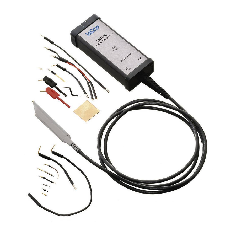
- Page 1 Operator’s Manual ZS1000, ZS1500, ZS2500 High-Impedance, Active Probe...
- Page 3 ZS1000, ZS1500, ZS2500 High-Impedance Active Probes Operator’s Manual...
- Page 4 Spare parts, replacement parts and repairs are warranted for 90 days. In exercising its warranty, Teledyne LeCroy, at its option, will either repair or replace any assembly returned within its warranty period to the Customer Service Department or an authorized service center.
-
Page 5: Table Of Contents
Probe Operation ..................9 Handling the Probe ................9 Connecting the Probe to an Oscilloscope .......... 9 Operation with a Teledyne LeCroy Oscilloscope ......10 Connecting the Probe to the Test Circuit ......... 10 High Frequency Measurements ............11 Probe Impedance and Equivalent Circuit .......... 14 ZS1x00 Impedance ................ - Page 6 Required Test Equipment ..............18 Preliminary Procedure ..............19 Functional Check ................20 Verification Procedure ..............21 Performance Verification Test Record ..........24 Reference Material ................26 Specifications ................... 26 Certifications ..................26 Contact Teledyne LeCroy ..............28 924282-00 Rev A...
-
Page 7: Safety Instructions
Operator’s Manual Safety Instructions This section contains instructions that must be observed to keep this oscilloscope accessory operating in a correct and safe condition. You are required to follow generally accepted safety procedures in addition to the precautions specified in this section. The overall safety of any system incorporating this accessory is the responsibility of the assembler of the system. -
Page 8: Operating Environment
WavePro and WaveMaster series platforms with firmware version 6.5.0.5 or later. With the ProBus interface, the ZS1000, ZS1500, and ZS2500 become an integral part of the oscilloscope. The probe can be controlled from the oscilloscope’s front panel. The oscilloscope provides power to the probe, so there is no need for a separate power supply or batteries. -
Page 9: Standard Accessories
Operator’s Manual Standard Accessories The ZS1000, ZS1500, and ZS2500 probes are shipped with the following standard accessories: Standard Accessory Quantity Replacement Part Number Straight Pin Lead – Short PK-ZS-003 Straight Pin Lead – Long PK-ZS-004 Right Angle Lead – Short PACC-LD003 Right Angle Lead –... -
Page 10: Features And Accessories
ZS Series High-Impedance, Active Probes Features and Accessories The ZS1000, ZS1500, and ZS2500s probes are provided with numerous features and accessories to make probing and connecting to different test points easier than ever. • The small, low mass probe head is designed for ease of use and high performance. -
Page 11: Tips
Operator’s Manual Tips Straight Tip The straight tip is rugged and designed for general probing. Fits in either probe socket. (PK-ZS-001) IC Lead Tip The IC Lead Tip is covered in insulation on all sides (except for a small edge), this tip was designed to prevent shorting neighboring IC leads. - Page 12 ZS Series High-Impedance, Active Probes Tips, continued Discrete SMD Tip The crescent shape of this tip is designed to fit tightly on capacitors, resistors, transistors and other surface mount components with discrete leads. Fits in either probe socket. 2.54 mm Square Pin 2.54 mm Square Pin Adapter.
-
Page 13: Grounds
Operator’s Manual Grounds Offset Ground The offset pin is designed to be attached to either socket of the probe head. The offset pin is the highest quality grounding solution and is recommended in high frequency applications. The offset ground is designed to connect to the ground socket and wrap around the probe head. -
Page 14: Leads
ZS Series High-Impedance, Active Probes Leads While longer leads provide greater flexibility when connecting the probe to a circuit, the added inductance may degrade the fidelity of high frequency signals. See Section 4 for additional information. Short and Long These leads have a socket on one end and a square pin Straight Pin Lead on the other to connect to the input or ground socket of the probe body, and may be used for general... -
Page 15: Probe Holder
(wear wrist strap, etc.) when using or handling the probe. Connecting the Probe to an Oscilloscope The ZS1000, ZS1500, and ZS2500 probes have been designed for use with Teledyne LeCroy’s WaveSurfer, WaveRunner, WavePro, and WaveMaster platforms equipped with the ProBus interface. When you attach the probe output connector to the oscilloscope’s input connector, the oscilloscope... -
Page 16: Operation With A Teledyne Lecroy Oscilloscope
ZS Series High-Impedance, Active Probes Operation with a Teledyne LeCroy Oscilloscope When the ZS1000, ZS1500, or ZS2500 probe is connected to any compatible Teledyne LeCroy oscilloscope, the displayed scale factor and measurement values are automatically adjusted. The probe can be controlled through the oscilloscope graphical user interface. -
Page 17: High Frequency Measurements
Operator’s Manual High Frequency Measurements Probe Input Loading When you touch a probe to the circuit under test, the probe will affect your measurement because of the probe’s input impedance introduced into the circuit. All probes present resistive, capacitive and inductive loading. Inductive Loading (Lead Length) A significant element in this circuit is the inductance shown in the input ground leads of the oscilloscope probe. - Page 18 ZS Series High-Impedance, Active Probes The resonant frequency of a series LC circuit can be raised by decreasing the inductance, capacitance or both. Since the input capacitance is already very low and cannot be reduced, you can only try to reduce the inductance. This can be accomplished by using the shortest possible input lead as well as the shortest possible ground lead.
- Page 19 Operator’s Manual Where Ctotal is the combined probe and circuit capacitance and Rtotal is combined circuit and probe resistance. For a setup where Ct = 0.9 pF and a source resistance is 250 Ω, the measured rise time will be 0.495 ns, which will correspond to a bandwidth of 909 MHz, assuming no inductive loads.
-
Page 20: Probe Impedance And Equivalent Circuit
ZS Series High-Impedance, Active Probes Probe Impedance and Equivalent Circuit ZS1x00 Impedance 1000000 100000 10000 1000 10Hz 1kHz 100kHz 10MHz 1000MHz ZS1x00 Equivalent Circuit 924282-00 Rev A... -
Page 21: Zs2500 Impedance
Operator’s Manual ZS2500 Impedance 1000000 100000 10000 1000 100Hz 1kHz 10kHz 100kHz 1MHz 10MHz 100MHz1000MHz 10000MHz ZS2500 Equivalent Circuit 924282-00 Rev A... -
Page 22: Care And Maintenance
Service Strategy The ZS1000, ZS1500, and ZS2500 probes utilize fine pitch surface mount devices. It is therefore impractical to attempt to repair in the field. Defective probes must be returned to a Teledyne LeCroy service facility for diagnosis and exchange. - Page 23 Operator’s Manual Return shipment should be prepaid. Teledyne LeCroy cannot accept COD or Collect Return shipments. We recommend air-freighting. Follow these steps for a smooth product return. 1. Contact your local Teledyne Lecroy sales or service representative to obtain a Return Material Authorization.
-
Page 24: Replacement Parts
This procedure can be used to verify the warranted characteristics of the ZS1000, ZS1500, and ZS2500 High Impedance Active Probe. The recommended calibration interval for the model ZS1000, ZS1500, and ZS2500 is one year. The complete performance verification procedure should be performed as the first step of annual calibration. -
Page 25: Preliminary Procedure
Pomona 5187-C-36 Cable, 36” Preliminary Procedure 1. Connect the ZS1000, ZS1500, or ZS2500 probe to the female end of the ProBus Extension Cable. Connect the male end of the ProBus Extension Cable to channel 1 of the oscilloscope. 2. Turn the oscilloscope on and allow at least 30 minutes warm-up time for the ZS1000, ZS1500, or ZS2500 and test equipment before performing the Verification Procedure. -
Page 26: Functional Check
20 mV/div to 2 mV/div. 7. Reconnect the ProBus extender Cable to the oscilloscope. The warranted characteristics of the ZS1000, ZS1500, and ZS2500 are valid at any temperature within the Environmental Characteristics listed in the Specifications. -
Page 27: Verification Procedure
Operator’s Manual Verification Procedure A. Output Zero Voltage Output Zero Voltage Test Setup 1. Connect one end of a BNC cable to the female BNC connector on the probe end of the ProBus extender cable. Connect the precision 50 Ω terminator to the other end of the BNC cable. - Page 28 ZS Series High-Impedance, Active Probes B. LF Attenuation Accuracy LF Attenuation Accuracy Setup 1. Disconnect the BNC tee at the power supply from the dual banana plug adapter. Connect the BNC tee to the output of the function gen erator. (Use a 50 Ω...
- Page 29 Operator’s Manual 6. Set the mode of the function generator to sine wave, the frequency to 70 Hz and the output amplitude to 5 Vrms ±10 mV as measured on the DMM. 7. Record the output voltage to 1 mV resolution as "Generator Output Voltage" in the Test Record.
-
Page 30: Performance Verification Test Record
This completes the Performance Verification of the ZS1000, ZS1500, or ZS2500. Complete and file the Test Record, as required to support your internal calibration procedure. Apply suitable calibration label to the ZS1000, ZS1500, or ZS2500 housing as required. NOTE: The function generator used in this Performance Verification Procedure is used for making relative measurements. -
Page 31: Test Record
Operator’s Manual Item Tested Item Serial Number Date Technician Equipment Used Instrument Model Serial Number Calibration Due Date Oscilloscope Digital Multimeter Function Generator Test Record UTPUT OLTAGE Step Description Intermediate Data Output Zero (Test limit ≤ ±200 μV) A-5. LF A TTENUATION CCURACY Step... -
Page 32: Reference Material
ZS Series High-Impedance, Active Probes Reference Material Specifications Please refer to the Teledyne LeCroy website at teledynelecroy.com for detailed specification information. Certifications This section contains the instrument’s Electromagnetic Compatibility (EMC), Safety and Environmental certifications. EMC Compliance EC D - EMC... -
Page 33: Safety Compliance
The probe is subject to disposal and recycling regulations that vary by country and region. Many countries prohibit the disposal of waste electronic equipment in standard waste receptacles. For more information about proper disposal and recycling of your Teledyne LeCroy product, please visit teledynelecroy.com/recycle. ESTRICTION OF... -
Page 34: Contact Teledyne Lecroy
Support: Sales: Ph: 800-909-7112 / 408-653-1260 customersupport@teledynelecroy.com psgsupport@teledynelecroy.com Singapore, Oscillosocpes European Headquarters Teledyne LeCroy Singapore Pte Ltd. Teledyne LeCroy SA 4, Rue Moïse Marcinhes Blk 750C Chai Chee Road #02-08 Case postale 341 Technopark @ Chai Chee 1217 Meyrin 1... - Page 37 Mouser Electronics Authorized Distributor Click to View Pricing, Inventory, Delivery & Lifecycle Information: Teledyne LeCroy ZS1000 ZS1500 ZS1000-QUADPAK PK-ZS-004 PK-ZS-005...