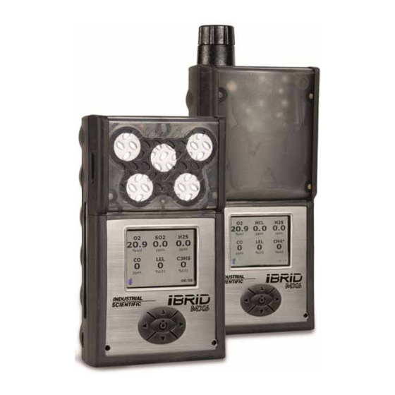
Industrial Scientific MX6 iBrid Operation Manual
Multi-gas monitor
Hide thumbs
Also See for MX6 iBrid:
- Operation manual (32 pages) ,
- Quick start (2 pages) ,
- Technical bulletin (2 pages)

Related Manuals for Industrial Scientific MX6 iBrid


Summary of Contents for Industrial Scientific MX6 iBrid
- Page 1 MX6 iBrid ™ Multi-gas Monitor Operation Guide Part Number: 17130279-1 Revision 13 Release Date June 30, 2015...
- Page 2 Industrial Scientific Corporation. Pittsburgh, PA USA Shanghai, China © 2007, 2009, 2011, 2012, 2013, 2014, 2015 Industrial Scientific Corporation All rights reserved. Published 2015...
-
Page 3: Table Of Contents
Contents General Information ....................1 Certifications ....................... 1 Warnings and Cautionary Statements ..............3 Key Features ......................6 Quick Start Menu Flowcharts ................9 Recommended Practices ..................11 Procedures ......................11 Procedure Frequency ..................12 ... -
Page 5: General Information
Warnings and Cautionary Statements Key Features Quick-start Menu Flowcharts ERTIFICATIONS Each MX6 iBrid is certified by one or more certifying bodies (CBs). The approved uses for which a unit is certified appear on labels affixed to the instrument. When a new certification is received, it is not retroactive to any unit that does not bear the marking on its label. - Page 6 Certifications Directive or Certification marking ANZEx Ex ia s Zone 0 I Ex ia s Zone 0 IIC T4 IP64 Permissible for PA Bituminous Underground Mines China CPC Metrology Pattern Approval China Ex Ex ia d I Ex ia d IIC T4 China MA Approval for Mining Products: CH4, O2, CO, and CO2 Class I, Groups A B C D T4...
-
Page 7: Warnings And Cautionary Statements
The MX6 multi-gas monitor complies with relevant provisions of European ATEX directive 2006/95/EC and 94/9/EC 94/9/EC and EMC directive 2004/108/EC. The EC type examination certificate is DEMKO 07 ATEX 0626395X; for equipment group and category II 1G; with marking code Ex ia IIC T4 Ga for an ambient temperature range of -20°C to 40°C, with the alkaline battery pack P/N 17131046-3 or -20°C to 55°C with the li-ion battery pack, P/Ns 17131038-1, and 17131038-2. - Page 8 recommended. Oxygen-deficient atmospheres may cause combustible gas readings to be lower than actual concentrations. Oxygen-enriched atmospheres may cause combustible gas readings to be higher than actual concentrations. Verify the calibration of the combustible gas sensor after any incident where the combustible gas content has caused the instrument to display an over-range condition.
- Page 9 CAUTION: For compliance determinations required by 30 CFR 75, Subpart D, the monitor must display "CH4" and “%VOL” during the monitor's start-up sequence. CAUTION: The Model MX6 iBrid Multi-Gas Monitor must be configured to include a catalytic sensor, Model 4L-LEL, P/N 1710-5081, (CH4, 0-5% v/v).
-
Page 10: Key Features
CAUTION: The IR (infrared) methane sensor reading is not to be used for methane concentrations below 5% in air. CAUTION: The Model MX6 iBrid Multi-Gas Monitor must be calibrated according to the procedure specified in the instruction manual. CAUTION: In applications requiring MSHA certification, the IR sensor for detecting up to 100% v/v methane-in-air the sensor must be calibrated manually;... - Page 11 EATURES The LCD backlight flashes as part of all alarm sequences, except for the battery low condition. The visual alarm is also used as the confidence indicator which, when enabled, blinks the LEDs once every 30 seconds. Infrared (I/R) An optical media interface (per IrDA physical layer Port specification) is located on the bottom of the instrument and is used for infrared (I/R) data transmissions at speeds of 115200...
- Page 12 The data log is downloaded when the unit is docked in a compatible docking station and may be accessed through iNet Control, Docking Station Server Admin Console (DSSAC), and Industrial Scientific Accessory Software. NOTE: Data are saved in case of power loss.
-
Page 13: Quick Start Menu Flowcharts
UICK TART LOWCHARTS... -
Page 15: Recommended Practices
Recommended Practices Procedures Procedure Frequency First Use ROCEDURES When completed regularly, the procedures defined below help to maintain proper instrument functionality and enhance operator safety. Configuration. The configuration process allows qualified personnel to review and adjust a unit's settings. Bump Test (or "functional test"). Bump testing checks for sensor and alarm functionality. -
Page 16: Procedure Frequency
ROCEDURE REQUENCY Industrial Scientific Corporation (ISC) minimum frequency recommendations for each procedure are summarized in the table below. These recommendations are based on field data, safe work procedures, industry best practices, and regulatory standards to enhance worker safety. - Page 17 or docking station; this may require up to eight hours. Note that the LCD on the MX6 shows that the battery is charging. After a unit is fully charged, qualified personnel should configure and calibrate it before first use (see chapters 5 and 6).
-
Page 19: Instrument Basics
Instrument Basics Hardware Overview Power On and Shutdown Gas-monitoring Display Screen ARDWARE VERVIEW The MX6 multigas monitor is a handheld, “dockable” instrument for personal protection. The five-way navigation button is shown in detail below. The button symbols are used within this document’s instructional text. Sensor Openings (Filters Beneath) Sensor Filter... -
Page 20: Power On And Shutdown
OWER N AND HUTDOWN Two operation basics are powering on the instrument and shutting it down. Power on. To power on the MX6 instrument, press and hold for at least 3 seconds. After power on, a series of start-up screens is displayed on the LCD. Start-up screens may vary depending on the unit’s configuration. -
Page 21: Gas-Monitoring Display Screen
Shutdown. To shut down the instrument, hold for more than two seconds. A confirmation screen is displayed to provide for user verification of the shutdown. MONITORING ISPLAY CREEN The gas-monitoring display screen for a six-sensor instrument is reproduced below. Reading the gas-monitoring display screen sensor type gas concentration unit of measure... -
Page 23: Operation
If the alarm is a STEL or TWA, the word “STEL” or “TWA” is shown to indicate the corresponding alarm. As described below, some events (e.g., pump fault) may be addressed by the instrument operator or a service technician. Other events require instruction from or service by Industrial Scientific. - Page 24 If the unit remains in pump fault, contact a Pump fault alarm supervisor or Industrial Scientific. A data-related function has failed for one or more of the installed sensors. Each failed sensors is indicated by a gas reading of “ERR” and is not operational.
-
Page 25: Menu System
A critical hardware or system fault has occurred and indicated on screen by a four digit number, which begins with 3 (3850 shown). Qualified personnel should Contact Industrial Scientific for assistance. System Alarm YSTEM The operation-mode root menu is the Operation-mode root menu entry point to any feature. -
Page 26: Navigation
AVIGATION Continuing with the sample screen from above, the instrument operator has already activated the operation-mode root menu and the dropdown menu for “View”. The keypad is used to navigate as described below. Keypad Navigation Sample screen Button press Result Activate the battery information screen. -
Page 27: Locating Operation-Mode Features
Display screen symbols Symbol Meaning ► Navigation The “Display” menu item has an additional screen to which the instrument operator can navigate. Action: Press to see the next screen. ● Enabled (on) The screen symbols indicate the following: - The numeric display style is enabled (on). - The text and graphical display styles are disabled (off). - Page 28 menu. The feature location list (below) shows the dropdown menus and describes the options that are accessible from each menu item. Feature location list Dropdown menu Menu item Accessible options View Display Choose a display style (numeric, text, or graph) for the gas-monitoring screen.
- Page 29 Feature location list Dropdown menu Menu item Accessible options View any sensor's most recent calibration date and its span trends. For a PID or LEL sensor, view its unit of measure along with its RF or correlation factor. Location View a diagram of the installed sensor locations.
-
Page 31: Configuration
Configuration Access Locating Configuration-mode Settings CCESS Using the instructions provided in Chapter 4, qualified personnel can navigate the menu system to enter and work in configuration mode. Menu system terminology is re-introduced below along with configuration-mode access instructions. Entering configuration mode Instruction Display Screen Terminology... - Page 32 Entering configuration mode Instruction Display Screen Terminology the user will be prompted to enter the configuration-mode password. Press ▼ or ▲ to select a character. Press ► to create the next character, or ◄ to delete the last. Press to highlight the password, then ▼to highlight the “OK”...
- Page 33 Display screen symbols Symbol Meaning ► Navigation Each menu item has an additional screen to which the safety team member can navigate. Action: Press to see the next screen. Note: MSHA instruments with the wireless data transfer option enabled from the factory will feataure a “Wireless” item on the config dropdown menu.
-
Page 34: Locating Configuration-Mode Settings
Display screen symbols Symbol Meaning Data entry Enter text or values in a data field. Actions: Press ► or ◄ to move the highlight among data fields and buttons. On a highlighted data field: - Press ▲ (or ▼) to increment (or decrement) the value or to scroll among choices. - Page 35 Settings location list Dropdown menu Item Accessible settings Disable or enable alarm indicators when the unit is docked. Enable the confidence indicator and select the indicator types (audio, visual, or vibrate). *It is possible to disable all three alarm indicators. As a precaution, a confirmation screen requires the safety team member to confirm or cancel the action.
- Page 36 Settings location list Dropdown menu Item Accessible settings Wireless MSHA factory-enabled units only. Choose the interval at which data are wirelessly transmitted. 0 = off Interval value range = 1−300 seconds Sensor Sensors Enable or disable a sensor. Set alarm values (high, low, and STEL) and the TWA time base.
- Page 37 Settings location list Dropdown menu Item Accessible settings RF List Mark any response factor (RF) as a favorite. Create custom RFs and set the gas type and response factor for each. Location View the unit’s sensor location map. Data Options Set the data log recording interval or adjust the TWA time period.
- Page 38 After changes are made in configuration mode, they can be saved to the instrument profile or to another profile. Exiting configuration mode Item Result Dropdown menu Exit Exit and “[x]” exits configuration mode and returns to the gas-monitoring display screen. Changes that have been made in configuration are saved to the instrument profile only;...
-
Page 39: Tasks, Diagrams, And Accessories
Tasks, Diagrams, and Accessories Power assessment Zero Calibrate Bump Test 3-Dimensional Diagram Accessories OWER SSESSMENT The Battery icon on the gas-readings display screen visually reflects the current status of the battery life. Depending on the installed LCD, one of two different icons may appear for each charge level. -
Page 40: Zero
From the operation-mode root menu, activate the “Sensor” dropdown menu. Highlight the “Zero All” item and press . The unit asks the instrument operator to confirm the zero request. If “Cancel” is selected, the user is returned to the gas-monitoring display screen and the zeroing is skipped. -
Page 41: Calibrate
ALIBRATE The instrument alarms are deactivated during the calibration to save battery life. If “Calibrate” is selected, the instrument displays the confirmation screen shown below. If “Cancel” is selected, the user is returned to the gas-monitoring display screen. If the user selects “OK”, all the installed sensors are zeroed first (following the “Zero All”... -
Page 42: Bump Test
From the operation-mode root menu, activate the “Sensor” dropdown menu. Highlight the “Bump Test” item and press The unit asks the instrument operator to confirm the bump test request. If “Cancel” is selected, the user is returned to the gas-monitoring display screen. -
Page 43: Three-Dimensional Diagram
HREE DIMENSIONAL IAGRAM Refer to the three-dimensional diagram for disassembled views of the instrument. Use the diagram number to identify parts, part numbers, and field-replaceable items (see diagram key below). Items shown in the above diagram, but NOT listed in the table below are not field replaceable Key for the MX6 diagram Field-replaceable parts only Diagram... - Page 44 Belt Clip 17127762 Belt Clip Screw, M3.5 x 8mm 17127820 Diffusion Cover w/Sensor Water Barrier 17128265 Replacement Sensors Carbon Monoxide Sensor 17124975-1 Hydrogen Sulfide Sensor 17124975-2 Oxygen Sensor 17124975-3 Nitrogen Dioxide Sensor 17124975-4 Sulfur Dioxide Sensor 17124975-5 Ammonia Sensor 17124975-6 Chlorine Sensor 17124975-7 Chlorine Dioxide Sensor...
-
Page 45: Accessories
Extended Range Battery (MSHA and AUS) 17131038-5 Alkaline Battery Pack (UL, CSA, and ATEX) 17131046-3 Alkaline Battery Pack (MSHA) 17131046-6 Pump (SP6) Dust Filter and Water Stop 17058157 Pump Inlet and Filter Cap 17129909 Pump Inlet and Filter Cap for use with 6 ' 17141581 extendable probe CCESSORIES... -
Page 46: Specifications And Warranty
-40 °C to +55 °C (-40 °F to +131 °F) Humidity range 15–95% relative humidity (RH) noncondensing (during continuous operation) Pressure range 1 atm ± 0.2 atm Maximum time Up to 1 year Note: Industrial Scientific recommends that infrequently used lithium-ion batteries be fully charged every four months. -
Page 47: Batteries
ATTERIES Battery properties Run time* Recharge time (hours) (hours) Li-ion battery pack MX6 iBrid without pump < 7 MX6 iBrid with pump < 7 Extended range Li-ion battery pack MX6 iBrid without pump < 8 MX6 iBrid with pump < 8... -
Page 48: Sensors
ENSORS Sensor Specifications Sensor Properties Accuracy when calibrated with stated gas type and concentration Name Abbreviation Measurement Response time Calibration gas at temperature of calibration over full measurement and temperature (type) ranges (nominal) Resolu- Range Accuracy (subrange) Temperature Accuracy tion range range Oxygen... - Page 49 Sensor Specifications Sensor Properties Accuracy when calibrated with stated gas type and concentration Name Abbreviation Measurement Response time Calibration gas at temperature of calibration over full measurement and temperature (type) ranges (nominal) Resolu- Range Accuracy (subrange) Temperature Accuracy tion range range Carbon Monoxide (High ±5% (0 to 1500 ppm)
- Page 50 Sensor Specifications Sensor Properties Accuracy when calibrated with stated gas type and concentration Name Abbreviation Measurement Response time Calibration gas at temperature of calibration over full measurement and temperature (type) ranges (nominal) Resolu- Range Accuracy (subrange) Temperature Accuracy tion range range Hydrogen Sulfide ±5% (0 to 200 ppm)
-
Page 51: Lel Data
Toxic Gas Sensor Cross-sensitivity Table Target Gas Sensor Low) ClO2 — — -165 — — — ClO2 — — — — — — — — — — — — — — — — — — — — — -100 — —... - Page 52 LEL D LEL correlation factors for combustible gases Sample gas* LEL correlation factors (% vol) Calibration gas Butane Hexane Hydrogen Methane Pentane Propane Ethylene 2.7% 0.80 0.60 1.40 1.30 0.70 0.90 Hexane 1.1% 1.71 1.00 3.04 2.86 1.42 1.77 Hydrogen 4.0% 0.56 0.33...
-
Page 53: Warranty
REPLACEMENT OR REPAIR OF SUCH NONCONFORMING GOODS OR REFUND OF THE ORIGINAL PURCHASE PRICE OF THE NONCONFORMING GOODS. IN NO EVENT WILL INDUSTRIAL SCIENTIFIC BE LIABLE FOR ANY OTHER SPECIAL, INCIDENTAL OR CONSEQUENTIAL OR OTHER SIMILAR DAMAGES, INCLUDING LOSS OF PROFIT OR LOSS OF USE, ARISING OUT... - Page 54 It is expressly agreed by the parties that any technical or other advice given by Industrial Scientific with respect to the use of the goods or services is given without charge and at Buyer’s risk; therefore, Industrial Scientific assumes no obligations or liability for the advice given or results obtained.
- Page 59 1 Life Way Pittsburgh, PA 15205-7500 Although every effort is made to ensure accuracy, the specifications of this product and the content herein are subject to change without notice. ©2007, 2009, 2011, 2012, 2013, 2014, and 2015 Industrial Scientific. All rights reserved.
-
Page 60: Contact Information
服务热线:+86 400 820 2515 To locate a nearby distributor of our products or an Industrial Scientific service center or business office, visit us at www.indsci.com. Rendez-vous sur notre site Web www.indsci.com, si vous voulez trouver un distributeur de nos produits près de chez vous, ou, si vous recherchez un centre de service ou un bureau Industrial Scientific.