Table of Contents
Advertisement
Quick Links
Download this manual
See also:
User Manual
Advertisement
Table of Contents

Related Manuals for Vaisala hmdw110 series


Summary of Contents for Vaisala hmdw110 series
- Page 1 USER'S GUIDE Vaisala HMDW110 Series Humidity and Temperature Transmitters M211726EN-A...
- Page 2 The contents of this manual are subject to change without prior notice. This manual does not create any legally binding obligations for Vaisala towards customers or end users. All legally binding obligations and agreements are included exclusively in the applicable supply contract or the General Conditions...
-
Page 3: Table Of Contents
About This Document Documentation Conventions Safety ESD Protection Recycling Trademarks Software License Warranty 2 Product Overview HMDW110 Series Overview Output Parameters Explained HMD110/112 Parts HMW110/112 Parts HMS110/112 Parts Component Board Analog Output Overrange Behavior 3 Installation Selecting Location HMD110/112 Installation... - Page 4 5 Maintenance Cleaning Calibration and Adjustment Adjustment Types Adjustment Points Calibration and Adjustment Using a Hand-Held Meter and a Reference Probe One-Point Humidity Calibration and Adjustment Using a Hand-Held Meter and HMK15 Humidity Calibrator Two-Point Humidity Calibration and Adjustment using a computer and a HMK15 Humidity Calibrator Two-Point Temperature Calibration and Adjustment using a Computer...
-
Page 5: General Information
Document Code Description M211726EN-A This document. July 2014. First version. Table 2 Related Documents Document Code Description M211692EN HMDW110 Series Quick Guide M210297EN HM70 User's Guide M210185EN HMK15 User's Guide M211691EN RDP100 User's Guide Documentation Conventions Warnings alert you to a serious hazard. If you do not read and follow instructions very carefully at this point, there is a risk of injury or even death. -
Page 6: Safety
1 General Information Safety The HMDW110 series transmitter delivered to you has been tested for safety and approved as shipped from the factory. Note the following precautions: Do not modify the unit. Improper modification can damage the product or lead to malfunction. -
Page 7: Software License
1 General Information Software License This product contains software developed by Vaisala. Use of the software is governed by license terms and conditions included in the applicable supply contract or, in the absence of separate license terms and conditions, by the General License Conditions of Vaisala Group. -
Page 8: Product Overview
HMDW110 series transmitters can be connected to Vaisala’s RDP100 panel display for real-time viewing of the measurements. HMDW110 series can also supply the operating power to the display using only the loop power from the outputs. -
Page 9: Output Parameters Explained
2 Product Overview Output Parameters Explained HMDW110 series transmitters offer several output parameters. Relative humidity (RH) and temperature (T) are the measured parameters, the others are calculated based on RH and T. Table 3 HMDW110 Series Output Parameters Parameter Symbol Units... -
Page 10: Hmd110/112 Parts
2 Product Overview HMD110/112 Parts Figure 1 HMD110/112 Parts 1 = PTFE membrane filter. 2 = Sensors for humidity and temperature. 3 = Fastening flange. 4 = Tightening screw for fastening flange. 5 = Type label. 6 = Transmitter cover. 7 = Component board. -
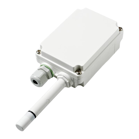
Page 11: Hmw110/112 Parts
2 Product Overview HMW110/112 Parts Figure 2 HMW110/112 Parts 1 = Screw holes for mounting (2 pcs). 2 = Cable gland. 3 = Sensors for humidity and temperature. 4 = PTFE filter. 5 = Type label. 6 = Component board. See Component Board on page 11. 7 = Probe. -
Page 12: Hms110/112 Parts
2 Product Overview HMS110/112 Parts Figure 3 HMS110/112 Parts 1 = Radiation shield. Do not remove for installation, only when replacing the sensor or filter. 2 = Long screws that keep the radiation shield in place (2 pcs), 3 mm hex socket. 3 = Sensors for humidity and temperature under PTFE membrane filter. 4 = Component board. -
Page 13: Component Board
4 ... 20 mA outputs (loop powered). There is also a service port for configuration and calibration use. Figure 4 HMDW110 Series Component Board 1 = Terminal block for 4 ... 20 mA current loop outputs. 2 = Service port connector (4-pin M8). -
Page 14: Analog Output Overrange Behavior
2 Product Overview Analog Output Overrange Behavior Analog outputs of the HMDW100 series transmitters have a defined behavior when the values measured by the transmitter are outside the scaled analog output range: Output is clipped at the end of the scaled output range. You can allow the output exceed the scaled range by 10% with the aover serial command. -
Page 15: Installation
3 Installation INSTALLATION Selecting Location When mounting duct model transmitters: Avoid installing in a location where condensation may fall on the sensor inside the duct. Position the sensor in the center of the duct. Select a site where the transmitter can be installed horizontally, onto the side of the duct. -
Page 16: Hmd110/112 Installation
3 Installation HMD110/112 Installation Medium size crosshead screwdriver (Pozidriv) for screws on cover and flange. Small slotted screwdriver for screw terminals. Drill with 2.5 mm and 13 mm bits for making the installation holes. Tools for cutting and stripping wires. 19 mm open-end wrench for tightening the cable gland. - Page 17 3 Installation 4. Push the probe of the transmitter through the flange and into the duct.The probe should reach far enough so that the sensor is located in the middle of the duct. Figure 6 HMD110/112 Centering Inside Duct 5. Secure the transmitter to the flange by tightening the screw on the flange that holds the probe in place.
-
Page 18: Hmw110/112 Installation
3 Installation HMW110/112 Installation Medium size crosshead screwdriver (Pozidriv) for cover screws. Small slotted screwdriver for screw terminals. Two installation screws: Ø ≤ 3.5 mm, head Ø ≤ 8 mm. Depending on the wall material and screw type, you may need a drill and a suitable drill bit to make installation holes for screws. -
Page 19: Hms110/112 Installation
3 Installation 2. Open the transmitter cover, and route the cable through the cable gland. Connect the wires to the screw terminals according to the wiring instructions: Wiring HMDW110 on page 19 Wiring HMDW110 with RDP100 on page 21 For the arrangement of the screw terminals, see section Component Board on page 11. - Page 20 3 Installation 3. Adjust the length of cable between the cable gland and the terminal blocks. Make the cable short enough to close the cover without leaving a cable loop in the transmitter. 4. Disconnect the wired screw terminal blocks by pulling them off from the component board.
-
Page 21: Wiring Hmdw110
3 Installation 6. Plug in the screw terminal blocks, close the cover, and tighten the screws. 7. Secure the cable to the pole using a zip tie, or on the wall using cable clips. Allow some cable to hang down from the cable gland to prevent water from entering the transmitter along the cable. -
Page 22: Wiring Both Current Loops With A Single Power Supply
Wiring Both Current Loops With a Single Power Supply Figure 9 HMDW110 Wiring with Single Power Supply HMDW110 Power Supply Requirements HMDW110 series transmitters are designed for a supply voltage range of 10 ... 28 VDC. The minimum required voltage depends on the loop resistance (0 ... 600 Ω) as shown below. -
Page 23: Wiring Hmdw110 With Rdp100
(terminals 7 and 8) is optional. Connect the RDP100 Remote Display Panel using terminals 1 ... 4. The HMDW110 series transmitter provides both power and data to the RDP100. Figure 11 HMDW110 Wiring with RDP100 Remote Display Panel When using the RDP100 with HMDW110 series transmitters, do not connect the Extpwr jumper to the RDP100 component board. -
Page 24: Service Port
Before plugging in a connection cable to the service port, perform the following steps: 1. Open the cover of the HMDW110 series transmitter. 2. If the terminal block for terminals 5 ... 8 is wired, pull it out. This disconnects the transmitter from supply voltage and prevents possible equipment damage that may be caused by ground loops. -
Page 25: Terminal Application Settings
One stop bit Number of the virtual COM port that has been created for your cable by the Vaisala USB driver. You can check which port the USB cable is using with the Vaisala USB Device Finder application that has been installed in the Windows Start menu. -
Page 26: Serial Commands
4 Service Port Serial Commands The notation <cr> refers to the carriage return control character, which you can send in a terminal application by pressing enter on your keyboard. Before entering commands, send a <cr> to clear the command buffer. You can enter the commands in uppercase or lowercase. -
Page 27: Device Information And Status
Sensor number : H0090003 Sensor model : Humicap 180R Order code : HMD1102A1VA1 Cal. date : 20140619 Cal. info : VAISALA/HEL Time : 01:43:43 Serial mode STOP Baud P D S 19200 N 8 1 Output interval: Serial delay Address Filter 1.000... - Page 28 4 Service Port Table 6 Errs Command Syntax Description Show active error(s). Possible error errs<cr> messages are listed below. For more information, see Error Messages on page 54. No errors T meas error F meas error RH sensor failure T ambient error Program flash check sum error Parameter flash check sum error INFOA check sum error...
- Page 29 TIME UNIT Table 8 System Command Syntax Description system<cr> Show firmware information. Example: vers Device Name : HMD112 Copyright : Copyright (c) Vaisala Oyj 2013. All rights reserved. SW Name : HMD112 SW date : 2014-04-14 SW version : 1.0.6...
-
Page 30: Serial Line Output And Communication
4 Service Port Table 9 Time Command Syntax Description time<cr> Show transmitter uptime (time since last reset) in hh:mm:ss. Example: time Time : 00:54:51 Serial Line Output and Communication Measurement Output Table 10 Send Command Syntax Description send<cr> Output a single measurement message. Output a single measurement message from send [aaa]<cr>... -
Page 31: Measurement Output Format
4 Service Port Table 12 S Command Syntax Description s<cr> Stop the continuous outputting of measurement values. Example: T= 22.8 'C RH= 39.5 %RH Td= 8.3 'C Tw= 14.5 'C h= 40.4 kJ/kg T= 22.8 'C RH= 39.5 %RH Td= 8.3 'C Tw= 14.5 'C h= 40.4 kJ/kg Since the interface is half-duplex, you must enter the s command... - Page 32 4 Service Port Table 15 Form Command Syntax Description form<cr> Show the currently used measurement format. form /<cr> Reset measurement format to default. Set a new measurement format. form [sss]<cr> sss = String consisting of modifiers and abbreviations for measured parameters. See the tables below.
-
Page 33: Serial Line Communication
4 Service Port Modifier Description Name of the measurement unit using x number of characters. For example, u3 shows the name of the measurement unit with three characters. addr Transmitter address. Transmitter serial number. time Time since transmitter was started or reset. Modulus-65536 checksum of message sent so far, ASCII encoded hexadecimal notation. - Page 34 4 Service Port Table 21 Seri Command Syntax Description seri<cr> Show current serial line settings. Set new serial line settings for RS-485 line seri [baud p d s]<cr> (also affects the service port). The new settings are taken into use when the device is reset or powered up.
-
Page 35: Analog Output
4 Service Port Table 23 Smode Command Syntax Description smode<cr> Show current start-up operating mode of the serial line, and prompt to enter new mode. New mode is taken into use when the device is reset or powered up. Set serial line start-up operating mode. smode [mode]<cr>... - Page 36 4 Service Port Table 25 Amode Command Syntax Description amode<cr> Show currently set analog output mode. Example: amode Ch1 output 4 ... 20 mA Ch2 output 4 ... 20 mA Table 26 Aover Command Syntax Description aover<cr> Show current aover status. Set analog output overrange to: aover [on|off]<cr>...
- Page 37 4 Service Port Table 27 Asel Command Syntax Description asel ?<cr> Show currently set analog output parameters and scaling. asel<cr> Show currently set analog output parameters and scaling, prompt to enter new scaling values. Set new output parameters for both asel [ch1 ch2]<cr>...
-
Page 38: Calibration And Adjustment Commands
4 Service Port Table 28 Atest Command Syntax Description Set analog channels to defined output value atest [ch1 ch2]<cr> (in mA). ch1 = Output value for channel 1. ch2 = Output value for channel 2. atest<cr> End analog output testing mode, return outputs to normal. - Page 39 4 Service Port Table 30 Crhclr Command Syntax Description crhclr<cr> Clear the current user adjustment for humidity. Factory calibration remains. Example: crhclr Table 31 Ct Command Syntax Description Start the two-point temperature calibration ct<cr> and adjustment sequence. For a full adjustment procedure, see section Two- Point Temperature Calibration and Adjustment using a Computer on page 49.
- Page 40 4 Service Port Table 33 Fcrh Command Syntax Description fcrh<cr> Start the two-point humidity calibration and adjustment sequence. If you have changed the humidity sensor of the device yourself, you must perform a two-point humidity calibration and adjustment using this command.
-
Page 41: Other Commands
4 Service Port Table 35 Li Command Syntax Description Enter values for offset and gain parameters li<cr> for user adjustment. Useful for restoring some earlier state of user adjustment. Use this command only to restore values you have previously written down based on the output from the l command, or to restore the default offset and gain. - Page 42 4 Service Port Table 37 Frestore Command Syntax Description Restores the factory default settings. All frestore<cr> user-made settings are lost, including user calibration. Reset the transmitter after giving this command. If you have replaced the ® HUMICAP humidity sensor of the device yourself, you must redo the two-point humidity calibration using the FCRH...
-
Page 43: Maintenance
For contact information, see section Product returns on page 55. HMDW110 series transmitters are fully calibrated as shipped from factory. You can use the service port to calibrate and adjust the humidity and temperature measurement of the transmitter as needed. If you think the transmitter is not... -
Page 44: Adjustment Types
Check that there is no moisture on the probe. If the sensor has become wet, you must allow it to dry before you can measure. Adjustment Types You can perform a one-point calibration and adjustment with Vaisala hand-held meters that utilize the MI70 measurement indicator (for example, HM70). See the following sections:... -
Page 45: Calibration And Adjustment Using A Hand-Held Meter And A Reference Probe
2. Connect the reference probe to port I of the MI70 indicator (the measurement display that is included in the HM70 package). 3. Prepare the HMDW110 series transmitter for a service port connection as instructed in section Connecting to the Service Port on page 22. - Page 46 HMDW110 series transmitter and the reference probe. Depending on the result, proceed as follows: If the HMDW110 series transmitter is within its accuracy specification, there is no need to proceed with the adjustment. Select Back and Exit to leave the adjustment mode.
-
Page 47: One-Point Humidity Calibration And Adjustment Using A Hand-Held Meter And Hmk15 Humidity Calibrator
Connection cable for HM70 hand-held meter (219980SP) Medium size cross-head screwdriver (Pozidriv) 1. Prepare the HMDW110 series transmitter for a service port connection as instructed in section Connecting to the Service Port on page 22. 2. Plug in the connection cable 219980SP to the service port of the HMDW110 series transmitter, and the other end to port I of the MI70 indicator. -
Page 48: Two-Point Humidity Calibration And Adjustment Using A Computer And A Hmk15 Humidity Calibrator
humidity sensor of the transmitter, perform the procedure below so that you use the FCRH command instead of the CRH command. 1. Prepare the HMDW110 series transmitter for a service port connection as instructed in section Connecting to the Service Port on page 22. - Page 49 5 Maintenance 2. Plug in the connection cable 219690 to the service port of the HMDW110 series transmitter, and the other end to a free USB port on your computer. 3. Remove the filter on the probe. This exposes the sensors to damage, so handle the transmitter carefully.
- Page 50 5 Maintenance 10. Press enter to refresh the measured value (to see if the measurement is now stable). When it is, enter the value of the first reference point and press enter. 11.5378 1. ref ? <cr> 11.5379 1. ref ? <cr> 11.5379 1.
-
Page 51: Two-Point Temperature Calibration And Adjustment Using A Computer
+140 °F) with more than 30 °C (86 °F) difference Medium size cross-head screwdriver (Pozidriv) 1. Prepare the HMDW110 series transmitter for a service port connection as instructed in section Connecting to the Service Port on page 22. 2. Plug in the connection cable 219690 to the service port of the HMDW110 series transmitter, and the other end to a free USB port on your computer. - Page 52 5 Maintenance 7. Give the l command to view the currently active user adjustment parameters. Example: default values of the user adjustment parameters (no user adjustment done). Cp offset : 0.00000000E+00 Cp gain 1.00000000E+00 offset : 0.00000000E+00 gain 1.00000000E+00 8. Give the ct command to start the calibration and adjustment sequence. The transmitter shows the measured T value and prompts you to enter the real temperature of the first reference point.
-
Page 53: Replacing The Humicap® Sensor On Hmd110/112 And Hmw110/112
5 Maintenance 13. Give the l command to verify that new values for user adjustment parameters T offset and T gain have been stored. Example: user adjustment parameters after two-point temperature adjustment. Your values will be different. Cp offset : 0.00000000E+00 Cp gain 1.00000000E+00 offset :... -
Page 54: Replacing The Humicap® Sensor On Hms110/112
5 Maintenance 3. Remove the filter to access the sensors. ® 1 = Vaisala HUMICAP sensor. Handle by the plastic frame. 2 = Temperature sensor. Do not touch or attempt to remove. 3 = Sensor socket. 4 = Transmitter probe. - Page 55 6. Tilt the radiation shield away from the opened tab. This opens the second tab on the other side, allowing you to remove the radiation shield. 7. Remove the filter to access the sensors. ® 1 = Vaisala HUMICAP sensor. Handle by the plastic frame. 2 = Temperature sensor. Do not touch or attempt to remove.
-
Page 56: Troubleshooting
Temperature sensor is short Check that sensor legs are circuited, damaged, or not short circuited. Contact a missing. Vaisala Service Center if sensor is damaged. F meas error Humidity sensor is wet. Dry the sensor by gently blowing dry instrument air on RH sensor failure... -
Page 57: Technical Support
5 Troubleshooting Technical Support For technical questions, contact the Vaisala technical support by e-mail at helpdesk@vaisala.com. Provide at least the following supporting information: Name and model of the product in question Serial number of the product Name and location of the installation site Name and contact information of a technically competent person who can provide further information on the problem. -
Page 58: Technical Data
6 Technical Data TECHNICAL DATA Specifications Table 40 Performance Property Specification Relative humidity Measurement range 0 ... 100 %RH Accuracy Temperature range +10 ... +30 °C (+50 ... +86 °F) 0 ... 90 %RH ±2 %RH 90 ... 100 %RH ±3 %RH Temperature range -20 ... - Page 59 Analog output 4 ... 20 mA, loop powered Loop resistance 0 ... 600 Ω Supply voltage at 0 Ω load 10 ... 28 VDC at 600 Ω load 20 ... 28 VDC Data input for RDP100 Remote Panel Display RS485, Vaisala proprietary protocol...
-
Page 60: Dimensions
6 Technical Data Dimensions All dimensions are in millimeters (mm). Figure 13 HMS110/112 Dimensions Figure 14 HMD110/112 Dimensions... -
Page 61: Spare Parts And Accessories
6 Technical Data Figure 15 HMW110/112 Dimensions Spare Parts and Accessories Information on spare parts, accessories, and calibration products is available online at www.vaisala.com and store.vaisala.com. Table 44 Spare Parts and Accessories Item Order Code Remote Panel Display RDP100 Conduit fitting + O-ring (M16x1.5 / NPT1/2 Inch) 210675SP Conduit fitting + O-ring (M16x1.5 / PG9, RE-MS) - Page 62 *M211726EN*...