Table of Contents
Advertisement
Quick Links
Download this manual
See also:
User Manual
Advertisement
Table of Contents

Related Manuals for Vaisala PTU300


Summary of Contents for Vaisala PTU300
- Page 1 USER'S GUIDE Vaisala Combined Pressure, Humidity and Temperature Transmitter PTU300 M210796EN-C...
- Page 2 The contents are subject to change without prior notice. Please observe that this manual does not create any legally binding obligations for Vaisala towards the customer or end user. All legally binding commitments and agreements are included exclusively in the applicable supply contract or Conditions of...
-
Page 3: Table Of Contents
Trademarks ................15 License Agreement ..............15 Warranty.................. 16 CHAPTER 2 PRODUCT OVERVIEW................17 Introduction to PTU300............17 Basic Features and Options..........18 New and improved features compared to PTU200..18 Pressure Measurement............19 Structure of the Transmitter ..........20 Probe Options .............. - Page 4 User's Guide ______________________________________________________________________ D-9 Connector ..............37 Connections to a 24 VAC Power Supply......38 Probe Mounting ..............39 General Instructions for Probes with Cable......39 PTU303 for General Use.............41 PTU307 for High Humidities..........41 Temperature Probe (Optional) ..........42 Optional Modules ..............43 Power Supply Module ............43 Installation ..............44 Warnings ................45 Galvanic Isolation for Output ..........48...
- Page 5 INTV ................104 ECHO................104 Pressure Average Calculation........... 105 Pressure............... 105 Relative Humidity (RH) and Temperature (T) Filtering 106 FILT................106 Device Information ............106 Using Serial Line ............107 ? ................... 107 HELP................108 ERRS ................108 VAISALA ________________________________________________________________________ 3...
- Page 6 User's Guide ______________________________________________________________________ VERS................108 Resetting Transmitter By Using Serial Line ......109 RESET................109 Locking Menu/Keypad by Using Serial Line......109 LOCK................109 Data Recording ..............110 Selecting Data Recording Quantities ........110 DSEL ................110 View Recorded Data ............111 DIR ................111 PLAY ................112 Deleting the Recorded Files ..........113 UNDELETE ..............114 Analog Output Settings ............114 Changing Output Mode and Range........114...
- Page 7 Changing the Probe Filter ..........139 Changing the Sensor ............140 Error States ............... 141 Technical Support ..............143 Return Instructions .............. 143 Vaisala Service Centers............144 CHAPTER 6 CALIBRATION AND ADJUSTMENT............145 Pressure ................145 Opening And Closing the Adjustment Mode..... 146 Pressure Adjustment ............
- Page 8 User's Guide ______________________________________________________________________ CHAPTER 7 TECHNICAL DATA ..................159 Specifications ...............159 Performance ..............159 Barometric pressure .............159 Relative Humidity ............160 Temperature (+ Operating pressure ranges) ....160 Optional Temperature Probe........161 Calculated Variables ............162 Accuracies Of Calculated Variables ........162 Accuracy of Dewpoint Temperature °C......162 Accuracy of Mixing Ratio g/kg (Ambient Pressure 1013 mbar) ................163 Accuracy of Wet Bulb Temperature °C ......163...
- Page 9 Connection Example Between PC Serial Port and User Port.. 74 Figure 47 Network Interface Menu ............78 Figure 48 IP Configuration Menu.............. 78 Figure 49 Wireless LAN Settings.............. 81 Figure 50 Entering Network SSID ............81 Figure 51 Selecting the Wireless Network Type ........81 VAISALA ________________________________________________________________________ 7...
- Page 10 Figure 83 Vapor Tight Installation............178 Figure 84 Wall Mounting Installation............179 Figure 85 Climate Chamber Installation (not Available from Vaisala) ..180 Figure 86 Example of Installation Through Roof ........181 Figure 87 Meteorological Installation Kit for Outdoor Installation ...182 8 ___________________________________________________________________ M210796EN-C...
- Page 11 Basic Quantities Measured by PTU300 ........19 Table 4 Optional Quantities Measured by PTU300....... 19 Table 5 Optional Pressure Quantities Measured by PTU300 ....19 Table 6 Wiring of 8-Pin Connector ............36 Table 7 Pin Assignments to RS-232/485 Serial Output ......37 Table 8 Connecting the Twisted Pair Wires to the Screw Terminals ..
- Page 12 User's Guide ______________________________________________________________________ This page intentionally left blank. 10 __________________________________________________________________ M210796EN-C...
-
Page 13: General Information
Chapter 1 ________________________________________________________ General Information CHAPTER 1 GENERAL INFORMATION About This Manual This manual provides information for installing, operating, and maintaining the Vaisala Combined Pressure, Humidity and Temperature Transmitter PTU300. Version Information Table 1 Manual Revisions Manual Code Description M210796EN-A... -
Page 14: General Safety Considerations
Product Related Safety Precautions The PTU300 delivered to you has been tested for safety and approved as shipped from the factory. Note the following precautions: WARNING Ground the product, and verify outdoor installation grounding periodically to minimize shock hazard. -
Page 15: Esd Protection
Chapter 1 ________________________________________________________ General Information ESD Protection Electrostatic Discharge (ESD) can cause immediate or latent damage to electronic circuits. Vaisala products are adequately protected against ESD for their intended use. However, it is possible to damage the product by delivering electrostatic discharges when touching, removing, or inserting any objects inside the equipment housing. -
Page 16: Transmitters With Wlan Interface
User's Guide ______________________________________________________________________ - Reorient or relocate the receiving antenna. - Increase the separation between the equipment and receiver. - Connect the equipment into an outlet on a circuit different from that to which the receiver is connected. - Consult the dealer or an experienced radio/TV technician for help. Transmitters with WLAN Interface This device has been designed to operate with a 2 dBi half-wave antenna. -
Page 17: Trademarks
Microsoft Corporation in the United States and/or other countries. License Agreement All rights to any software are held by Vaisala or third parties. The customer is allowed to use the software only to the extent that is provided by the applicable supply contract or Software License Agreement. -
Page 18: Warranty
Products should Vaisala so require, be sent to the works supplied hereunder, which obligations of Vaisala or to such other place as Vaisala may liabilities are hereby expressly cancelled and indicate in writing, freight and insurance waived. Vaisala's liability... -
Page 19: Chapter 2 Product Overview
Alternatively, digital outputs RS-232 (standard) or RS-422/485 (optional) can be selected. A local display is also available. The quantities measured and calculated by PTU300 are presented in Table 3 on page 19. The quantities available as an option are presented in Table 4 on page 19 below. -
Page 20: Basic Features And Options
User's Guide ______________________________________________________________________ Basic Features and Options - Pressure redundancy option: 2 sensors in one unit - Two accuracy classes for pressure measurement - Several probes for various applications - A 3 h trend and tendency available in pressure measurement - Calculated output quantities available - Different probe mounting kits, sensor protection options and probe cable lengths... -
Page 21: Pressure Measurement
The PTU300 series transmitters use a BAROCAP silicon capacitive absolute sensor developed by Vaisala for barometric pressure measurement applications. The measurement principle of the PTU300 series digital transmitters is based on an advanced RC oscillator and three reference capacitors against which the capacitive pressure sensor and capacitive temperature compensation sensor are continuosly measured. -
Page 22: Structure Of The Transmitter
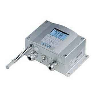
User's Guide ______________________________________________________________________ Structure of the Transmitter 0604-005 Figure 1 Transmitter Body The numbers refer to Figure 1 above: Signal + powering cable gland, or WLAN antenna connector Pressure port Cable gland for optional module Cover screw (4 pcs) Display with keypad (optional) Cover LED 20 _______________________________________________________________ M210796EN-C... -
Page 23: Figure 2 Inside The Transmitter
Chapter 2 __________________________________________________________ Product Overview 0604-060 Figure 2 Inside the Transmitter Numbers refer to Figure 2 above: Service port (RS-232) DIP switches for analog output settings Power supply and signal wiring screw terminals Relay, RS-422/485, data logger, LAN, WLAN, or analog output module (optional) Grounding connector for power supply module Adjustment buttons (chemical purge buttons) with indicator... -
Page 24: Probe Options
User's Guide ______________________________________________________________________ Probe Options 0601-010 Figure 3 Probe Options Numbers refer to Figure 3 above: PTU301 Probe for wall mounting. PTU303 Probe for general use. PTU307 for demanding processes (optionally warmed and vapor tight probe). Temperature probe. Probe cable lengths are 2 m, 5 m and 10 m. 22 _______________________________________________________________ M210796EN-C... -
Page 25: Warmed Probe Ptu307
Chapter 2 __________________________________________________________ Product Overview Warmed Probe PTU307 Temperature difference between the probe and external environment can cause a risk of condensation on the sensor. A wet probe cannot observe the actual humidity in the ambient air. If the condensed water is contaminated, the life span of the probe may shorten and calibration may change. - Page 26 User's Guide ______________________________________________________________________ This page intentionally left blank. 24 _______________________________________________________________ M210796EN-C...
-
Page 27: Chapter 3 Installation
Chapter 3 _______________________________________________________________ Installation CHAPTER 3 INSTALLATION This chapter provides you with information that is intended to help you install the product. Mounting the Housing The housing can be mounted either without the mounting plate or with optional mounting plates. Standard Mounting without Mounting Plate Mount the housing by fastening the transmitter to the wall with 4... -
Page 28: Wall Mounting With Wall Mounting Kit
Numbers refer to Figure 5 on page 26: Plastic mounting plate Mount the plate to wall with 4 screws M6 (not provided) The arched side up Fasten PTU300 to the mounting plate with 4 fixing screws M3 (provided) Holes for wall/junction box mounting 26 _______________________________________________________________ M210796EN-C... -
Page 29: Mounting With Din Rail Installation Kit
Mounting with DIN Rail Installation DIN rail installation kit includes a wall mounting kit, 2 clip-fasteners and 2 screws M4 x 10 DIN 7985 (Vaisala order code 215094). Attach two spring holders to the plastic mounting plate by using the screws provided in the installation kit. -
Page 30: Pole Installation With Installation Kit For Pole Or Pipeline
Pole Installation with Installation Kit for Pole or Pipeline Installation kit for pole or pipeline (Vaisala order code: 215108) includes the metal mounting plate and 4 mounting nuts for pole mounting. When mounting, the arrow in the metal mounting plate must point upwards, see Figure 10 on page 29. -
Page 31: Figure 10 Mounting With Metal Wall Mounting Plate
Numbers refer to Figure 10 above: Mount the plate to wall with 4 screws M8 (not provided) Fasten the PTU300 to the mounting plate with 4 fixing screws M6 (provided) Note the position of the arrow when mounting. This side must be up when mounting. -
Page 32: Mounting Rain Shield With Installation Kit
Mounting Rain Shield with Installation Kit Numbers refer to Figure 12 above: 1 = Fasten the rain shield with installation kit (Vaisala order code: 215109) to the metal mounting plate with 2 (M6) mounting screws (provided). 2 = Fasten the mounting plate with rain shield with installation kit to the wall or to the pole (see pole installation). -
Page 33: Figure 13 Panel Mounting Frame
Chapter 3 _______________________________________________________________ Installation Remove the paper protecting the adhesive tape on the frame, and attach the frame around the transmitter. Refer to Figure 13 below. 0704-002 Figure 13 Panel Mounting Frame The following numbers refer to Figure 13 above: Panel (not included) Panel mounting frame 0804-083... -
Page 34: Wiring
User's Guide ______________________________________________________________________ Wiring Cable Bushings A single electrical cable with a screen and three to ten wires is recommended for power and analog/serial connections. The cable diameter should be 8...11 mm. The number of cable bushings depends on the transmitter options. See the following recommendations for the cable bushings: 0604-059 Figure 15... -
Page 35: Grounding The Cables
Chapter 3 _______________________________________________________________ Installation Grounding the Cables Ground the screen of the electrical cable properly to achieve the best possible EMC performance. 0504-049 Figure 16 Grounding the Screen of Electrical Cable VAISALA____________________________________________________________________ 33... -
Page 36: Grounding The Transmitter Housing
Otherwise harmful ground currents may be generated. If it is needed to have galvanic isolation of the power supply line from the output signals, PTU300 can be ordered with optional output isolation module. This module prevents harmful grounding loops. Alternate Wiring Systems There are three optional ways to connect the transmitter: using basic wiring, using 8-Pin connector, or using D-9 connector. -
Page 37: Signal And Power Supply Wiring
Chapter 3 _______________________________________________________________ Installation Signal and Power Supply Wiring When wiring the power supply module, see section Power Supply Module on page 43. 0506-028 Figure 17 Screw Terminal Block on Motherboard Numbers refer to Figure 17 above: Power supply terminals 10 ... 35 VDC, 24 VAC User port (RS-232 terminals) Analog signal terminals WARNING... -
Page 38: 8-Pin Connector
User's Guide ______________________________________________________________________ - Third Analog Output on page 48 - LAN Interface on page 55 - WLAN Interface on page 56 Connect the power supply wires to the connectors: POWER 10...35V+ 24V~ (+) and (-) terminals. If you are using 24 VAC power supply, see the note below before connecting the supply wires. -
Page 39: D-9 Connector
Chapter 3 _______________________________________________________________ Installation D-9 Connector Figure 19 Wiring of Optional D-9 Connector Table 7 Pin Assignments to RS-232/485 Serial Output Wire Color Serial Signal RS-232 C RS-485 White Black Yellow Brown Ground Green Blue Ground for supply voltage Ground for supply voltage Grey Orange Supply voltage (10...30 VDC) Supply voltage (10...30 VDC) -
Page 40: Connections To A 24 Vac Power Supply
User's Guide ______________________________________________________________________ Connections to a 24 VAC Power Supply Separate floating supply for each transmitter is recommended (see the upper part of Figure 20 below). If you have to connect several transmitters or other instruments to one AC supply, the phase (~) must always be connected to the (+) connector of each transmitter (see the lower part of Figure 20). -
Page 41: Probe Mounting
Chapter 3 _______________________________________________________________ Installation Probe Mounting In humidity measurement and especially in calibration it is essential that temperature of the probe and measuring environment is the same. Even a small difference in temperature between the environment and the probe causes an error. As the curve below shows, if the temperature is +20 °C and the relative humidity 100 %RH, a difference of ±1 °C between the environment and the probe causes an error of ±6 %RH. -
Page 42: Figure 22 Horizontal Mounting Of Probe
User's Guide ______________________________________________________________________ 0507-024 Figure 22 Horizontal Mounting of Probe Numbers refer to Figure 22 above: 1 = To be sealed. 2 = To be insulated. 3 = Insulate the cable. 4 = Let the cable hang loosely. This prevents condensed water running to the sensor along the cable. -
Page 43: Ptu303 For General Use
If this is not possible and the probe must be inserted from the top, the point of entry must be carefully insulated. For Vaisala probe installation kits and some installation examples see Appendix A below on page 173. PTU303 for General Use The PTU303 is a small size (d=12mm) probe for general use, up to +80°C (+176°F). -
Page 44: Temperature Probe (Optional)
The PTU307 RH+T probe is suitable for temperatures up to +180°C (+356°F). Note that the operational temperature limit for the PTU307 probe is higher than for the PTU300 transmitter itself. The upper temperature limit for barometric pressure measurement is +60°C (140°F). -
Page 45: Optional Modules
Chapter 3 _______________________________________________________________ Installation Optional Modules Power Supply Module The AC (mains) power connection may be connected to the power supply module only by an authorized electrician. A readily accessible disconnect device shall be incorporated in the fixed wiring. 0506-027 Figure 24 Power Supply Module Numbers refer to Figure 24 above... -
Page 46: Installation
User's Guide ______________________________________________________________________ Installation Disconnect the power and open the transmitter cover. Remove the protective plug from the cable gland and thread the wires. In case the power supply module is installed in the factory, continue with the step 5. To attach the module fasten the power module to the bottom of the housing with four screws. -
Page 47: Warnings
Nätanslutningen (växelströmsanslutningen) får bara anslutas till strömförsörjningsmodulen av en behörig elektriker. Ta inte loss strömförsörjningsmodulen från mätaren när strömmen är på. Anslut inte strömförsörjningsmodulen till nätet när den inte är installerad i PTU300- mätaren Anslut alltid en skyddande jordningsplint. VAISALA____________________________________________________________________ 45... - Page 48 Netstrømskoblingen til må kun tilsluttes strømforsyningsmodulet af en autoriseret elinstallatør Strømforsyningsmodulet må ikke løsgøres fra senderen, mens spændingen er sluttet til. Slut ikke netspændingen til strømforsyningsmodulet, når det ikke er installeret i PTU300- senderen Forbind altid den beskyttende jordklemme! Dit product voldoet aan de eisen van de richtlijn 73/23 EEG (Laagspanningsrichtlijn).
- Page 49 Elektros tinklą su energijos tiekimo moduliu sujungti gali tik įgaliotas elektrikas. Niekada neišimkite energijos tiekimo modulio iš siųstuvo, kai maitinimas yra įjungtas. Jei energijos tiekimo modulis nėra įmontuotas PTU300 siųstuve, nejunkite jo į elektros tinklą. Visada prijunkite prie apsauginės įžeminimo jungties! Šis produkts atbilst Zemsprieguma direktīvai (73/23 EEC).
-
Page 50: Galvanic Isolation For Output
If galvanic isolation of the power supply line from the output signals is needed, can be ordered with optional output isolation PTU300 module. This module prevents harmful grounding loops. NOTE Output isolation module is not needed when using the power supply module. -
Page 51: Installation And Wiring
Chapter 3 _______________________________________________________________ Installation Installation and Wiring Disconnect the power. In case the analog output module is installed in the factory, continue with the step 4. To attach the module, open the transmitter cover and fasten the analog output module to the position for MODULE 1 with four screws. -
Page 52: Relays
User's Guide ______________________________________________________________________ Relays PTU300 can be equipped with one or two configurable relay modules. Each module contains two configurable relays. See the contact ratings in section Technical Specifications of Optional Modules on page 166. Installation and Wiring Disconnect the power and open the transmitter cover. In case the relay-module is installed in the factory, continue with step 5. -
Page 53: Figure 28 Relay Module
Chapter 3 _______________________________________________________________ Installation 0503-037 Figure 28 Relay Module Numbers refer to Figure 28 above: Indication led for the relay 1 or 3 Relay test buttons Flat cable pins Indication led for relay 2 or 4 The relay module may contain dangerous voltages even if the WARNING transmitter power has been disconnected. -
Page 54: Rs-422/485 Interface
User's Guide ______________________________________________________________________ RS-422/485 Interface 0503-029 Figure 29 RS-485 Module Numbers refer to Figure 29 above: Flat cable pins Selection switches Screw terminals for wiring Installation and Wiring Disconnect the power. In case the RS-485-module is installed in the factory, continue with the item 4. To attach the module, open the transmitter cover and fasten the RS-485 module to the bottom of the housing with four screws. -
Page 55: Figure 30 4-Wire Rs-485 Bus
Use the bus type (4-wire/2-wire) to select the selection switch 3. In 4-wire mode RS-485 master sends data to the PTU300 through terminals RxA and RxB and receives data from PTU300 through terminals TxA and TxB. -
Page 56: Figure 31 2-Wire Rs-485 Bus
User's Guide ______________________________________________________________________ Table 9 4-Wire (Switch 3:On) RS-485 master Data PTU300 → → ← ← Figure 31 2-Wire RS-485 Bus Table 10 2-Wire (Switch 3:Off) RS-485 master Data PTU300 ↔ ↔ When operating in communication mode RS-422, set both switches 3 and 4 to ON position (4-wire wiring is required for RS-422 mode). -
Page 57: Lan Interface
User Port is disabled. The LAN interface module must be installed at the factory (when ordering the transmitter), or by a Vaisala Service Center. Once installed, the module is automatically used by the transmitter. The physical connection to the network is made to the RJ45 connector on the LAN interface module, using a standard twisted pair Ethernet cable (10/100Base-T). -
Page 58: Wlan Interface
User's Guide ______________________________________________________________________ WLAN Interface The optional WLAN interface enables a wireless Ethernet connection (IEEE 802.11b) to the transmitter. The interface supports Wired Equivalent Privacy (WEP) and Wi-Fi Protected Access (WPA). For WEP, 64 and 128 bit encryption is supported, with open system or shared key authentication. -
Page 59: Attaching The Wlan Antenna
Attaching the WLAN Antenna The LAN interface module must be installed at the factory (when ordering the transmitter), or by a Vaisala Service Center. Before taking the transmitter into use, the user must attach the antenna of the WLAN interface into the RP-SMA connector on the transmitter cover. -
Page 60: Figure 34 Data Logger Module
The transmitter will also indicate the problem by activating the "Add-on module connection failure" error. If the module is not operating correctly, the transmitter must be sent to Vaisala for maintenance. The data logger module must be installed at the factory (when ordering the transmitter), or by a Vaisala Service Center. -
Page 61: Chapter 4 Operation
The pressure has an effect on humidity calculations and accuracy. Therefore, accurate calculations can be achieved only when the ambient pressure is taken into consideration. PTU300 uses measured pressure for compensation by default. See section Pressure Compensation Setting on page 99 for instructions on how to set the pressure. -
Page 62: Basic Display
User's Guide ______________________________________________________________________ Basic Display Display shows you the measurement values of the selected quantities in the selected units. You can select 1... 3 quantities for the basic display (see section Changing Quantities and Units on page 92). 0601-014 Figure 35 Basic Display Numbers refer to Figure 35 above: The Info shortcut key, see section Information on page 66... -
Page 63: Pressure 3H Trend And Tendency Reading
Chapter 4 ________________________________________________________________ Operation Pressure 3h Trend and Tendency Reading Using Basic Display 0604-056 Figure 36 Tendency Display indicators for pressure 3h trend and tendency above, where: Tendency: Increasing/decreasing graph symbol with the code number (for more information, see Figure 37, on page 62) P3h symbol Trend (middlemost numeric value) VAISALA____________________________________________________________________ 61... -
Page 64: Figure 37 Pressure Tendency Description
User's Guide ______________________________________________________________________ Pressure tendency graphics and codes: The characteristic symbols of pressure tendency during the 3 hours preceding the time of observation are described as follows: 0604-055 Figure 37 Pressure Tendency Description where: Increasing, then decreasing; atmospheric pressure the same or higher than three hours ago Increasing, then steady;... -
Page 65: Using Serial Line
Changing Quantities and Units, starting on page 92. Missing trend In addition to this the PTU300 series barometers output a code "*" when the pressure tendency has not yet been calculated that is, less than three hours have elapsed since the power-up of the barometer. -
Page 66: Graphic History
User's Guide ______________________________________________________________________ Graphic History The graphical display shows the data trend or min/max graph of the selected quantities, one at a time. The graph is updated automatically while measuring. 0706-052 Figure 38 Graphical Display Trend graph: Shows you a curve of average values. Each value is a calculated average over a period. -
Page 67: Figure 39 Graphical Display With Data Logger
Chapter 4 ________________________________________________________________ Operation time from the present to the chosen moment (without the logger module), or the date and time at the cursor position (when the logger module is installed). - If the optional data logger module is installed, you can scroll the cursor off the screen to move to a new point on the time axis. -
Page 68: Information Display
User's Guide ______________________________________________________________________ Information Display The information display contains current settings and status of the device. You can open the display by pressing the left function button INFO in the basic display. The following information will be shown: - current sensor operation (for example, chemical purge), if any, in progress - present or past unacknowledged errors, if any - device identification;... -
Page 69: Menus And Navigation
Chapter 4 ________________________________________________________________ Operation Menus and Navigation You can change settings and select functions in the menus. Open the MAIN MENU by pressing any of the arrow buttons ▼▲◄► in the basic display mode. Scroll the list upwards or downwards by pressing the up/down arrow buttons ▼▲.You can select an option by highlighting it. -
Page 70: Changing The Language
User's Guide ______________________________________________________________________ Changing the Language Go back to the basic display by keeping the right-hand button pressed for four seconds. Open the Main menu by pressing any of the ▼▲◄► buttons. Scroll to the System menu option, and press the ► button. The menu option is indicated with the wrench symbol. -
Page 71: Display Contrast Setting
Chapter 4 ________________________________________________________________ Operation Display Contrast Setting Open the MAIN MENU by pressing any of the arrow buttons. Select Display, press the right arrow button. Select Contrast, press the ADJUST key. Adjust the contrast by pressing the left/right arrow buttons. Press the OK key and then EXIT to return to the basic display Keypad Lock (Keyguard) This function locks the keypad and prevents unintentional key presses. -
Page 72: Factory Settings
User's Guide ______________________________________________________________________ Factory Settings Use the display/keypad to restore the factory settings. This operation does not affect the adjustments. Only settings available in the menus are restored. Press any of the arrow buttons to open the MAIN MENU. Select System, press the right arrow button. Select Factory settings and press the REVERT key to confirm your selection. -
Page 73: Configuring A Display Alarm
Chapter 4 ________________________________________________________________ Operation Multiple alarms can be active at the same time; the alarm that was triggered first will be shown on the display. The next active alarm is revealed when the currently shown alarm is acknowledged by pressing the OK button. -
Page 74: Mi70 Link Program For Data Handling
Connect your PC to the transmitter using the serial interface, LAN interface, or the WLAN interface. Refer to sections Serial Line Communication on page 73 and LAN Communication on page 76. Check that the PTU300 is powered. Start the MI70 Link program. 72 _______________________________________________________________ M210796EN-C... -
Page 75: Serial Line Communication
COM port manually. The MI70 Link program, and the optional connection cables, are available from Vaisala. See list of accessories in section Options and Accessories on page 168. Serial Line Communication Connect the serial interface by using either the user port or the service port. -
Page 76: User Port Connection
After power-up the transmitter (in STOP-mode) outputs the software version and the command prompt. PTU300 / 3.01 > In RUN mode a measurement output starts immediately after power- User port cannot be used when the RS-485 module is connected. -
Page 77: Service Port Connection
The installation has reserved a COM port for the cable. Verify the port number, and the status of the cable, using the Vaisala USB Instrument Finder program that has been installed in the Windows Start menu. -
Page 78: Using The Service Port
User's Guide ______________________________________________________________________ There is no reason to uninstall the driver for normal use. However, if you wish to remove the driver files and all Vaisala USB cable devices, you can do so by uninstalling the entry for Vaisala USB Instrument Driver from the Add or Remove Programs (Programs and Features in Windows Vista) in the Windows Control Panel. -
Page 79: Ip Configuration
Chapter 4 ________________________________________________________________ Operation IP Configuration The IP settings of the LAN and WLAN interfaces are described in Table 16. The current settings can be viewed on the serial line or using the device information display; see section Information Display on page 66. -
Page 80: Figure 47 Network Interface Menu
User's Guide ______________________________________________________________________ 0802-113 Figure 47 Network Interface Menu The Network Interface menu also allows you to enable or disable the Web configuration option, or Disconnect all users that are currently accessing the LAN or WLAN interface. In the IP configuration menu, select Automatic configuration (DHCP), or enter the IP address, Netmask and Gateway manually. -
Page 81: Using Serial Line
Chapter 4 ________________________________________________________________ Operation Using Serial Line Use the serial line command NET to view or set the network settings for the LAN and WLAN interfaces. You can also refresh the network information or disconnect all active connections. NET [REFRESH] [DISCONNECT] [DHCP WEB] [DHCP IP SUBNET GATEWAY WEB] where REFRESH... -
Page 82: Wireless Lan Configuration
User's Guide ______________________________________________________________________ > >net off 192.168.0.101 255.255.255.0 192.168.0.1 off DHCP : OFF IP address : 192.168.0.101 Subnet mask : 255.255.255.0 Default gateway: 192.168.0.1 Web config. : OFF MAC address : 00:40:9d:2c:d2:05 Telnet : Connected > Wireless LAN Configuration The settings of the WLAN interface are described in Table 17. The current settings can be viewed on the serial line or using the device information display;... -
Page 83: Figure 49 Wireless Lan Settings
Chapter 4 ________________________________________________________________ Operation 0802-111 Figure 49 Wireless LAN Settings The Name entry on the page shows the SSID of the currently selected wireless network. To change the SSID, press the SET button. Use the ▲▼ arrow buttons to change the character under the cursor, and ◄►... -
Page 84: Using Serial Line
User's Guide ______________________________________________________________________ After setting the wireless network parameters, press the Exit button in the Wireless Network Settings menu. You will be asked to confirm the new settings. Note that when new settings are saved, all currently active WLAN connections are disconnected. -
Page 85: Telnet Settings
IP address of the interface. When accessing the web configuration page, you must first log in. Username: user Password: vaisala The web configuration page provides similar network configuration options as the serial line and the display/keypad. It also has additional options for advanced users. -
Page 86: Terminal Program Settings
Start HyperTerminal. To get help for starting HyperTerminal, click Start, select Help to open Windows help, and search for "HyperTerminal". In the New Connection window of the HyperTerminal, define a name for PTU300 serial connection, for example "Vaisala Transmitter". Click OK. 84 _______________________________________________________________ M210796EN-C... -
Page 87: Figure 53 Connecting Using Serial Interface
Chapter 4 ________________________________________________________________ Operation Select the connection type using the Connect using pull down menu. If you are connecting to the transmitter using the serial interface, select the PC communications port where the serial cable is connected and click OK. If you are using the USB-RJ45 cable to connect to the Service Port, check the communications port that the cable is using with the USB Instrument Finder program that has been installed in the Windows Start menu. -
Page 88: Figure 55 Hyper Terminal Serial Port Settings
User's Guide ______________________________________________________________________ If you selected a serial port, you must match the port settings in the Properties window with the transmitter’s serial interface (user port or service port). If you are using the USB-RJ45 cable, you are connecting to the service port. Verify that Flow control is set to None. -
Page 89: List Of Serial Commands
Chapter 4 ________________________________________________________________ Operation List of Serial Commands The bold text in the brackets is the default setting. To issue a command, type it on your computer and press the Enter key. Table 18 Measurement Commands Command Description Start the continuous outputting Stop the continuous outputting INTV [0 ... -
Page 90: Table 21 Chemical Purge Commands
User's Guide ______________________________________________________________________ Command Description UNDELETE Recover the deleted files that have not been overwritten Table 21 Chemical Purge Commands Command Description Set the automatic chemical purge PURGE Start the manual chemical purge Table 22 Calibration and Adjustment Commands Command Description Relative humidity calibration Temperature calibration... -
Page 91: Getting Measurement Message From Serial Line
Chapter 4 ________________________________________________________________ Operation Command Description PFIX Select pressure compensation using either a fixed value or using measured value AVRG Set pressure average period HHCP Set height offset for HCP calculation HQNH Set height offset for QNH calculation HQFE Set height offset for QFE calculation PSTAB Set the pressure stability indicator PDMAX... -
Page 92: Stopping Continuous Outputting
User's Guide ______________________________________________________________________ If a value is too long to fit to the allocated space in the output, or if there is an error in outputting the quantity, the value is displayed with stars ‘*’. Example: RH=***.* %RH T= 31.0 'C You can change the format of the output with the following commands: - Outputting interval can be changed with the INTV command. -
Page 93: Send D
Chapter 4 ________________________________________________________________ Operation Outputting Reading With Raw Data SEND D Example: >send d 24.1720 15.0399 -3.5743 189.2324 15.0709 15.0399 23.9765 Where the readings (from the left) are: 24.1720 = Temperature of the humidity probe ( ºC) 15.0399 = RH (%RH) -3.5743 = Tdf (C) 189.2324 = Capasitance (pF) -
Page 94: Formatting Serial Line Message
User's Guide ______________________________________________________________________ Formatting Serial Line Message FTIME and FDATE FTIME and FDATE commands will enable/disable output of time and date to the serial line. To add time to R and SEND outputs enter: FTIME [x] To add date to R and SEND outputs enter: FDATE [x] where ON or OFF... -
Page 95: Using Display/Keypad
Chapter 4 ________________________________________________________________ Operation Using Display/Keypad To select the display output quantities. Press any of the arrow buttons to open the MAIN MENU. Select Display, press the right arrow button. Select Quantities, press the right arrow button. Select quantities by pressing the up/down arrow buttons. Confirm the selection by pressing the SELECT key. -
Page 96: Table 28 The Modifiers
User's Guide ______________________________________________________________________ Formatter string consists of quantities and modifiers. When entering the command, use the abbreviations of the quantities. For more information on quantities, see Table 3 on page 19. The modifiers are presented in Table 28 below. Table 28 The modifiers Modifier Description... -
Page 97: Unit
Chapter 4 ________________________________________________________________ Operation Other examples: >form "RH=" 4.2 rh U5 #t "T=" t U3 #r #n >RH= 14.98%RH 74.68'F >form "Tfrost=" tdf U3 #t "Temp=" t U3 #r#n >Tfrost= 36.0'C Temp= 31.0'C Command ‘FORM ’ will return the default output format. The default output format depends on the device configuration. -
Page 98: Date And Time
User's Guide ______________________________________________________________________ Date and Time Using Display/Keypad If the optional Data Logger Module is installed, you can change the time and date using the display/keypad. Press any of the arrow buttons to open the MAIN MENU. Select System and press the ►arrow button to confirm your selection. -
Page 99: Nmea Data Format
Chapter 4 ________________________________________________________________ Operation NMEA Data Format The PTU300 transmitter can be used in connection with a GPS receiver. It responds to a GPS input command by outputting a single predefined NMEA format message or the transmitter serial number. NOTE The pressure unit has to be set as bar when the NMEA data output format is used. -
Page 100: Gps Commands
>send<cr> $PASHS,XDR,P,0.99710,B,S1630001,C,22.47,C.S1630001,H,20. 84,P,S1660001 > Example 2: "$PASHS,XDR,P," 1.5_P_",B,,C,"_3.2_T_",C,,H,"_RH_",P,"_#r_#n_ Output format: >send<cr> $PASHS,XDR,P,1.01148,B,,C, 27.11,C,,H, 54.29,P, > GPS Commands The PTU300 transmitter responds to following GPS specific application commands. *0100P9 Example: >*0100P9 <cr> $PASHS,XDR,P,1.03384,B,A2100012,C,22.28,C,A2100012,H,39. 65,P,A2100012 > *0200P9 Example: >*0200P9 <cr> 98 _______________________________________________________________ M210796EN-C... -
Page 101: Pressure Compensation Settings
O and inH O at 4°C. NOTE Pressure compensation is intended to be used in normal air only. When measuring in other gases, please contact Vaisala for further information. Using Display/Keypad Use display/keypad to set the pressure compensation. To select the pressure unit using display/keypad see section Changing Quantities and Units on page 92. -
Page 102: Using Serial Line
User's Guide ______________________________________________________________________ Selecting Measured P: Press the SELECT key and then exit the menu. Selecting Fixed: 1013.25hPa: Press the SELECT key, and then SET. You can move from a digit to another one by pressing the left/right arrow buttons. To change the unit, press the up/down arrow buttons. -
Page 103: Pfix
Chapter 4 ________________________________________________________________ Operation Example: 29.9213 inHg = 29.9213 x 33.86388 = 1013.25 hPa PFIX Use the PFIX command to select either P inputted or P measured. When PFIX is On, fixed PRES value is used When PFIX is Off, measured PRES value is used PSTAB Use the PSTAB command to define the pressure stability indicator reflecting maximum allowed pressure difference between two... -
Page 104: Pdmax Limit Works As Follows
User's Guide ______________________________________________________________________ Pdmax limit works as follows: >form 4.1 p1 " " p2 " " p " " u3 " " ERR #r#n Example1: Maximum pressure difference is within the limit >send 1034.2 1034.4 1034.3 hPa 0000 > Example2: Maximum pressure difference exceeds the limit >send 1034.2 1035.4 ****** hPa 1000 >... -
Page 105: Using Serial Line
Chapter 4 ________________________________________________________________ Operation Press the arrow buttons to select ECHO. Press ON to turn to it on. Press OFF to turn it off. Press the EXIT key to return to the basic display. The new user port settings set using the display/keypad are effective immediately. -
Page 106: Smode
User's Guide ______________________________________________________________________ SMODE Use the command SMODE to set the user port start-up operating mode. SMODE [xxxx] where xxx = STOP, RUN, POLL or SEND Table 30 Selection of Output Modes Mode Output Available Commands STOP Only with the SEND command All (default mode) Automatic output Only command S... -
Page 107: Pressure Average Calculation
Chapter 4 ________________________________________________________________ Operation ECHO [x] where ON (default) or NOTE You can use the SERI, SMODE, INTV and ECHO commands to change/view the user port settings even if you are currently connected to the service port. Pressure Average Calculation Pressure The averaging data filter calculates an average pressure over a certain period of time. -
Page 108: Relative Humidity (Rh) And Temperature (T) Filtering
User's Guide ______________________________________________________________________ Relative Humidity (RH) and Temperature (T) Filtering Table 31 Filtering Levels for Relative Humidity (RH) and Temperature (T) Setting Filtering level No filtering ON (default) Standard = short filtering (approximately 15 s moving average) EXTENDED Extended filtering (default: approximately 1 min average) Use display/keypad to set the filtering level. -
Page 109: Using Serial Line
Use the serial line command ? to check the current transmitter configuration. Command ?? is similar but can also be used if the transmitter is in POLL mode. Example: >? PTU300 / 3.01 Serial number : A2150004 Batch number : A1450004 Adjust. -
Page 110: Help
Error States on page 141 and Table 32 on page 142. Example: >errs No errors > Example: >ERRS FAIL Error: Temperature measurement malfunction Error: Humidity sensor open circuit > VERS Use the command VERS to display software version information. Example: >vers PTU300 / 3.01 > 108 ______________________________________________________________ M210796EN-C... -
Page 111: Resetting Transmitter By Using Serial Line
Chapter 4 ________________________________________________________________ Operation Resetting Transmitter By Using Serial Line RESET Resets the device. The user port switches to start-up output mode selected with command SMODE. Locking Menu/Keypad by Using Serial Line LOCK Use the LOCK command to prevent the user from entering the menu using the keypad, or to lock the keypad completely. -
Page 112: Data Recording
User's Guide ______________________________________________________________________ Examples: >lock 1 4444 Keyboard lock : 1 [4444] > >lock 1 Keyboard lock > Data Recording Data recording function is always on and collects data automatically into the memory of the device. If the optional data logger module is installed, the transmitter uses it automatically. -
Page 113: View Recorded Data
Chapter 4 ________________________________________________________________ Operation Enter the command without parameters and press ENTER to display current recording parameters. View Recorded Data If the device is provided with the optional display, the graphical display shows the data of the selected quantities, one at a time. For details about graphical display, see section Graphic History on page You may also dump the logged data to the serial line in numeric form with the following commands. -
Page 114: Play
User's Guide ______________________________________________________________________ Example (without data logger module): >dir File description Oldest data available No. of points (10 s intervals) 2008-04-11 23:41:10 (90 s intervals) 2008-04-11 20:41:11 (12 min intervals) 2008-04-10 21:03:41 (2 h intervals) 2008-03-31 18:03:41 (12 h intervals) 2008-02-04 12:03:41 (3 d intervals) 2007-03-04 00:03:41... -
Page 115: Deleting The Recorded Files
Chapter 4 ________________________________________________________________ Operation Example: >play 3 2007-05-05 00:00:00 2007-05-06 00:00:00 (12 min intervals) 2007-05-05 00:00:00 Date Time trend yyyy-mm-dd hh:mm:ss 2007-05-05 00:00:00 19.16 18.99 19.33 2007-05-05 00:12:00 19.30 19.09 19.55 2007-05-05 00:24:00 20.01 19.28 21.17 2007-05-05 00:36:00 21.21 20.98 21.44 2007-05-05 00:48:00... -
Page 116: Undelete
User's Guide ______________________________________________________________________ UNDELETE Similarly to the DELETE command, the UNDELETE command is used without any arguments. It will recover all deleted data that has not been overwritten yet. Analog Output Settings The analog outputs are set in the factory according to the order form. In case you want to change the settings, follow these instructions. -
Page 117: Figure 56 Current/Voltage Switches Of Output Modules
Chapter 4 ________________________________________________________________ Operation 0503-045 Figure 56 Current/Voltage Switches of Output Modules Numbers refer to Figure 56 above: Current/voltage selection output switches (from 1 to 2) Current/voltage range selection switches (from 3 to 7) in analog output 1 and 2. Switches for service use only. -
Page 118: Analog Output Quantities
User's Guide ______________________________________________________________________ Example: 0 ... 5 V voltage output selected for channel 1 and 4...20 mA selected for channel 2. OFF ON Selection █ █ Voltage output selected █ █ █ █ 0 ... 5 V selected █ █ █... -
Page 119: Amode/Asel
Chapter 4 ________________________________________________________________ Operation Select Quantity and press the CHANGE key. Select the quantity by using the up/down arrow buttons. Press the SELECT key to confirm your selection. Select Scale, lower limit, by pressing the up/down arrow buttons. Press the SET key. Adjust the lower limit value by pressing the arrow buttons up/down/left/right. -
Page 120: Analog Output Tests
User's Guide ______________________________________________________________________ Use the command ASEL [xxx yyy] as shown in the example below when using a device with two analog outputs. Example: >asel rh t p <cr> Ch1 RH : 0.00 %RH ? Ch1 RH high : 100.00 %RH ? Ch2 T : -40.00 'C ? Ch2 T... -
Page 121: Analog Output Fault Indication Setting
Chapter 4 ________________________________________________________________ Operation Example: >itest 20 5 Ch1 (Td ) 20.000 mA H'672A Ch2 (T 5.000 mA H'34F9 >itest Ch1 (Td ) -23.204 'C 16.238 mA H'FFFE Ch2 (T 22.889 'C 8.573 mA H'5950 > Analog Output Fault Indication Setting Factory default state for analog outputs during error condition is 0 V/ 0 mA. -
Page 122: Operation Of Relays
User's Guide ______________________________________________________________________ NOTE The error output value must be within a valid range of the output mode. NOTE The error output value is displayed only when there are minor electrical faults such as a humidity sensor damage. When there is a severe device malfunction, the error output value is not necessarily shown. -
Page 123: Hysteresis
Chapter 4 ________________________________________________________________ Operation 0610-076 Figure 57 Relay Output Modes Mode 4 is usually used if an alarm needs to be triggered when the measured value exceeds a safe range. The relay is active when measurement is in range, and is released if the value goes out of range or the measurement fails. -
Page 124: Relay Indicating Transmitter Error Status
User's Guide ______________________________________________________________________ Example: When the 'active above' value is 60 %RH and the hysteresis value is 5 %RH, relay activates when the relative humidity reaches 60 %RH. As the humidity decreases, relay releases at 55 %RH. If both setpoints are specified and "above" setpoint is lower than NOTE "below"... -
Page 125: Enabling/Disabling Relays
Chapter 4 ________________________________________________________________ Operation 0610-077 Figure 58 FAULT/ONLINE STATUS Relay Output Modes FAULT/ONLINE STATUS relays are usually used in conjunction with an analog output to obtain validity information for the output value. If transmitter loses its power, all status-based relays are released NOTE similarly to the case of an instrument failure. -
Page 126: Setting Relay Outputs
User's Guide ______________________________________________________________________ Setting Relay Outputs NOTE When having only one relay module installed, its relays are called 'relay 1' and 'relay 2'. When having two relay modules, the relays of the module connected to slot MODULE 1 are called 'relay 1' and relay 2'. 0706-055 Figure 59 Relay Indicators on Display... -
Page 127: Rsel
Chapter 4 ________________________________________________________________ Operation RSEL Use the serial line to select the quantity, setpoints and hysteresis or enable/disable the relay outputs. Enter the RSEL command. RSEL [q1 q2] where q1 = quantity for the relay 1 or Fault/Online q2 = quantity for the relay 2 or Fault/Online Factory setting: all relays disabled. -
Page 128: Testing Operation Of Relays
User's Guide ______________________________________________________________________ Rel3 Td below: 0.00 'C ? - Rel3 Td hyst : 1.00 'C ? 1 Rel3 Td enabl: OFF ? on Rel4 Td above: 0.00 'C ? 20 Rel4 Td below: 0.00 'C ? - Rel4 Td hyst : 0.00 'C ? 2 Rel4 Td enabl: OFF ? on... -
Page 129: Rtest
Echo function shall be always disabled (OFF) when using the 2-wire connection. When using the 4-wire connection you can disable/enable the echo setting. User port on PTU300 main board cannot be used and connected when NOTE RS-485 module is connected. Service port is operating normally. -
Page 130: Networking Commands
User's Guide ______________________________________________________________________ Networking Commands Set the RS-422/485 interface by using the following commands. The other serial line commands are presented in section List of Serial Commands on page 87. RS-485 configuration commands SERI; ECHO; SMODE; INTV and ADDR may be entered by using either the service port or RS- 422/485 port. -
Page 131: Echo
Chapter 4 ________________________________________________________________ Operation ECHO Use the ECHO command to enable/disable echo of characters received over the serial line. ECHO [x] where ON/OFF (default = OFF) When using 2-wire connection, echo must be always disabled. SMODE Use the SMODE command to set the default serial interface mode. SMODE [xxxx] where xxxx... -
Page 132: Addr
User's Guide ______________________________________________________________________ Sets the RUN mode output interval. The time interval is used only when the RUN mode is active. For example, the output interval is set to 10 minutes. >INTV 10 min Output intrv. : 10 min > Setting RUN output interval to zero enables the fastest possible output rate. -
Page 133: Close
Chapter 4 ________________________________________________________________ Operation OPEN [aa] where aa = address of the transmitter (0 ... 99) CLOSE The CLOSE command switches the transmitter back to the POLL mode. Example: >OPEN 2 (opens the line to transmitter 2, other transmitters stay in POLL mode) >CRH (for example, calibration performed) >CLOSE... -
Page 134: Automatic Chemical Purge (Interval Purge)
Automatic Chemical Purge (Interval Purge) When PTU300 leaves the factory the automatic chemical purge (if chosen) takes place repeatedly with the time intervals set in the factory. User can change the interval in which the purge takes place by using serial commands or with the optional display/keypad. -
Page 135: Chemical Purge In Power Up
Chapter 4 ________________________________________________________________ Operation Chemical Purge in Power Up Chemical purge (start-up purge) can be set to start within 10 seconds from the power-up of the device. Starting and Configuring Chemical Purge Using Buttons On Motherboard Start manual chemical purge by pressing simultaneously two PURGE buttons on the motherboard inside the transmitter for a few seconds. -
Page 136: Using Serial Line
User's Guide ______________________________________________________________________ 0706-006 Figure 62 Chemical Purge Settings - Select Automatic purge and turn it on or off by pressing the ON/OFF key. - Select Interval and press the SET key. Set the purge interval and the unit (hour/day) by using the arrow buttons. The interval must be set between 1 hour...10 days. -
Page 137: Pur
Chapter 4 ________________________________________________________________ Operation With PUR command you can enable or disable automatic and power- up chemical purge and set the interval for automatic purge. If the sensor is exposed to chemicals it is recommended to have the chemical purge done at least once in 720 min (=12 hours). In applications where the chemical exposure is not likely, the interval can be longer. -
Page 138: Setting Humidity Sensor Heating Using Display/Keypad
Setting Humidity Sensor Heating Using Display/Keypad When the PTU300 leaves the factory the sensor heating follows the factory default values. You can enable/disable the function, change the RH-limit and define the heating temperature and duration of this function. - Page 139 Chapter 4 ________________________________________________________________ Operation To configure the sensor heating use the XHEAT command without parameters. Enter the values after question mark. The available ranges include the following: Extra heat RH -limit (heating 0...100 %RH (default: 95 %RH) function starts-up above the setpoint) Extra heating temperature 0...200 ºC (default: 100 ºC)
- Page 140 User's Guide ______________________________________________________________________ This page intentionally left blank. 138 ______________________________________________________________ M210796EN-C...
-
Page 141: Periodic Maintenance
Install a new filter on the probe. When using the stainless steel filter, take care to tighten the filter properly (recommended force 5 Nm). New filters can be ordered from Vaisala, see section Options and Accessories on page 168. VAISALA___________________________________________________________________ 139... -
Page 142: Figure 64 Changing The Sensor
When replacing the sensor, the new sensor must be of the same type as the old sensor (for example, HUMICAP180L2). The sensor type can only be changed at a Vaisala Service Center. The user can change the HUMICAP180 and HUMICAP180L sensors Remove the filter from the probe. -
Page 143: Figure 65 Error Indicator And Error Message
Press the INFO key to display the error message. You can also check the error message via the serial interface by using the command ERRS. In case of constant error, please contact Vaisala, see section Vaisala Service Centers on page 144. VAISALA___________________________________________________________________ 141... -
Page 144: Table 32 Error Messages
Clean the probes from dirt, water, ice or other contaminants. Internal ADC read error Internal transmitter failure. Remove the transmitter and return the faulty unit to Vaisala Service. Additional temperature Check the integrity of the temperature probe and sensor short circuit the probe cable. -
Page 145: Technical Support
Contact a Vaisala Service Center or a local Vaisala representative. The latest contact information and instructions are available from www.vaisala.com. Addresses of the Service Centers are provided in section Vaisala Service Centers on page 144. Please have the following information on hand:... -
Page 146: Vaisala Service Centers
Include the information specified in step 2 in the box with the faulty product. Also include a detailed return address. Ship the box to the address specified by your Vaisala contact. Vaisala Service Centers Vaisala Service Centers perform calibrations and adjustments as well as repair and spare part services. -
Page 147: Calibration And Adjustment
Chapter 6 ___________________________________________________ Calibration and adjustment CHAPTER 6 CALIBRATION AND ADJUSTMENT The PTU300 is fully calibrated and adjusted as shipped from factory. Typical calibration interval is two years. Depending on the application it may be good to make more frequent checks. Calibration must be done always when there is a reason to believe that the device is not within the accuracy specifications. -
Page 148: Figure 66 Adjustment And Purge Buttons
User's Guide ______________________________________________________________________ NOTE Entering new linear or multipoint corrections will always cancel the previous corrections. It is advisable to write down the previous linear and multipoint corrections so that they will not be lost by mistake. Table 33 Adjustment and Calibration Commands Function Command linear corrections on/off... -
Page 149: Figure 67 Adjustment Menu
Chapter 6 ___________________________________________________ Calibration and adjustment Adjustment menu is displayed only when ADJ button (on the motherboard inside the transmitter) is pressed. 0706-054 Figure 67 Adjustment Menu Table 34 Indicator Led Functions Indicator Led Function Description LED off adjustment locked LED on adjustment available LED blinking evenly... -
Page 150: Point Adjustment Using Serial Line
User's Guide ______________________________________________________________________ Enter the actual pressure of the reference used using the up/down arrow buttons. Press the OK key. Press the YES key to perform the adjustment. Press the OK to return to the adjustment menu. 1-point Adjustment Using Serial Line NOTE Making adjustments is possible only after adjustments are unlocked. -
Page 151: Mpci
Chapter 6 ___________________________________________________ Calibration and adjustment Example: >lc P1 linear adj. : ON P1 1.reading : 950.000 P1 1.correction: 0.220 P1 2.reading : 1120.000 P1 2.correction: 0.150 MPCI Use the command MPCI to activate or deactivate multipoint adjustment function to enter new multipoint corrections to the transmitter to edit existing multipoint corrections. -
Page 152: Relative Humidity Adjustment
User's Guide ______________________________________________________________________ Use the command MPC to view current status of the multipoint corrections. Example: >mpc P1 multi adj. : ON P1 1.reading : 900.000 P1 1.correction: 0.200 P1 2.reading : 950.000 P1 2.correction: 0.220 P1 3.reading : 1000.000 P1 3.correction: 0.270 P1 4.reading : 1050.000... -
Page 153: Figure 68 Selecting Point 1 Reference Type
Chapter 6 ___________________________________________________ Calibration and adjustment Wait at least 30 minutes for the sensor to stabilize (the indicator led is lit continuously). Adjustment cannot be done if the conditions are not stabilized (indicator led is flashing). LiCl~11% When the indicator led is lit continuously press the button to adjust the 11 % RH condition. -
Page 154: Using Serial Line
Note that the difference between the two humidity references must be at least 50% RH. Connect the PTU300 to a PC. See section Serial Line Communication on page 73. Open a terminal program. Carry out the chemical purge (if available). - Page 155 Chapter 6 ___________________________________________________ Calibration and adjustment When the reading is stabilized, give the reference humidity after the question mark and press ENTER. >crh 11.25 Ref1 ? c 11.25 Ref1 ? c 11.25 Ref1 ? c 11.24 Ref1 ? c 11.24 Ref1 ? 11.3 Press any key when ready ...
-
Page 156: Relative Humidity Adjustment After Sensor Change
User's Guide ______________________________________________________________________ Relative Humidity Adjustment After Sensor Change Using Display/Keypad When using the optional display/keypad, follow the instructions on Using Display/Keypad on page 151 on page but select Adj. for new RH sensor (instead of 1-point/ 2-point adjustment). Using Serial Line After sensor change, carry out the procedure as described in previous sections. - Page 157 Chapter 6 ___________________________________________________ Calibration and adjustment Press the READY key when stabilized. Give the reference temperature by using the arrow buttons. When carrying out the 2-point adjustment, proceed to the next adjustment point and carry out the procedure as described in the previous items.
-
Page 158: Analog Output Adjustment (Ch1 And Ch2)
- current output: 2 mA and 18 mA - voltage output: 10 % and 90 % of the range Connect PTU300 to a calibrated current/voltage meter in order to measure either current or voltage depending on the selected output type. -
Page 159: Feeding Adjustment Information
Chapter 6 ___________________________________________________ Calibration and adjustment Measure the first analog output value with a multimeter. Give the measured value by using the arrow buttons. Press the OK key. Measure the second analog output value with a multimeter. Give the measured value by using the arrow buttons. Press the OK key. -
Page 160: Using Serial Line
User's Guide ______________________________________________________________________ Select i, press the SET key. Enter information text including 17 characters at maximum. Use the arrow buttons. Press the OK key. Press the EXIT key to return to the basic display. Using Serial Line CTEXT Use the CTEXT command to enter text to the adjustment information field. -
Page 161: Technical Data
Chapter 7 ____________________________________________________________ Technical data CHAPTER 7 TECHNICAL DATA This chapter provides the technical data of the product. Specifications Performance Barometric pressure Pressure range 500 ... 1100 hPa, 50 ... 1100 hPa Accuracy 500 ... 1100 hPa, 500 ... 1100 hPa 50 ... -
Page 162: Relative Humidity
User's Guide ______________________________________________________________________ Defined as ±2 standard deviation limits of accuracy of the working standard including traceability to NIST. Defined as the root sum of the squares (RSS) of endpoint non-linearity, hysteresis error, repeatability error and calibration uncertainty at room temperature. **** Defined as ±2 standard deviation limits of temperature dependence over the operating temperature range. -
Page 163: Figure 69 Accuracy Over Temperature Range
Chapter 7 ____________________________________________________________ Technical data Accuracy over temperature range (see graph below): 0605-104 Figure 69 Accuracy over Temperature Range Temperature sensor Pt 100 RTD 1/3 Class B IEC 751 Optional Temperature Probe Temperature measurement range: -70...+ 180 ºC (-94...+356 ºF) Typical accuracy: 0.1 ºC (0.18 ºF) Sensor:... -
Page 164: Table 35 Calculated Variables (Typical Ranges)
User's Guide ______________________________________________________________________ Calculated Variables Table 35 Calculated Variables (Typical Ranges) Variable PTU 301 PTU303 PTU 307 Dewpoint temperature -20...+60 ºC -20...+80 ºC -20...+100 ºC Mixing ratio 0...160 g/kg dry air 0...500 g/kg dry air 0...500 g/kg dry air Absolute humidity 0...160 g/m 0...500 g/m 0...500 g/m... -
Page 165: Accuracy Of Mixing Ratio G/Kg (Ambient Pressure
Chapter 7 ____________________________________________________________ Technical data Accuracy of Mixing Ratio g/kg (Ambient Pressure 1013 mbar) Relative humidity Temp. 0.003 0.003 0.003 0.003 0.003 0.004 0.004 0.004 — — 0.017 0.018 0.019 0.021 0.022 0.023 0.025 0.026 — — 0.08 0.09 0.09 0.10 0.10 0.11... -
Page 166: Figure 70 Accuracy In Dewpoint Measurement
User's Guide ______________________________________________________________________ Dewpoint Temperature (PTU307 Warmed Probe Option) Find the intersection of the dewpoint temperature curve and the dewpoint difference reading (process temperature-dewpoint temperature) on the x-axis and read the accuracy in dewpoint measurement on the y-axis. Dewpoint temperature (°C) Dewpoint difference (°C) 0508-017 Figure 70... -
Page 167: Inputs And Outputs
Chapter 7 ____________________________________________________________ Technical data Inputs and Outputs Operating voltage 10 ... 35 VDC, 24 VAC with optional power supply module 100 ... 240 VAC, 50/60 Hz Start-up time after power-up Power consumption @ 20 °C (Uin 24VDC) RS-232 max 28 mA Uout 3 x 0...1V / 0...5V / 0...10V max 33 mA Iout 3 x 0...20 mA... -
Page 168: Table 36 Transmitter Weight (In Kg/Lb)
User's Guide ______________________________________________________________________ Probe cable lengths 2 m, 5 m or 10 m Probe tube material PTU301 Chromed ABS plastic Other probes AISI 316L Housing material G-AlSi 10 Mg (DIN 1725) Housing classification IP 65 (NEMA 4) Transmitter Weight Table 36 Transmitter Weight (in kg/lb) Probe Type Probe Cable Length... -
Page 169: Relay Module
Chapter 7 ____________________________________________________________ Technical data Relay Module Operating temperature range -40 ... +60 ºC (-40 ... +140 ºF) Operating pressure range 500 ... 1300 mmHg Power consumption @24 V max 30 mA Contacts SPDT (change over), for example, Contact arrangement Form C Imax 0.5 A 250 VAC Imax... -
Page 170: Options And Accessories
User's Guide ______________________________________________________________________ Data Logger Module Operating temperature range -40 ... +60 ºC (-40 ... +140 ºF) Storage temperature range -55 ... +80 ºC (-67 ... +176 ºF) Power consumption @ 24V max 10 mA Logged parameters up to three with trend/min/max values for each Logging interval 10 s (fixed) - Page 171 Chapter 7 ____________________________________________________________ Technical data Description Item code Cable Gland and AGRO, for PTU303/307 HMP247CG Duct Installation Kit for PTU303/307 210697 Duct Installation Kit for Temperature Probe 215003 CONNECTION CABLES Serial Interface Cable 19446ZZ USB-RJ45 Serial Interface Cable 219685 Connection Cable for HM70 211339 HMI41 Connection Cable with RJ45 Connector 25917ZZ...
-
Page 172: Figure 71 Transmitter Body Dimensions
User's Guide ______________________________________________________________________ Dimensions (mm/inch) 0601-043 Figure 71 Transmitter Body Dimensions 170 ______________________________________________________________ M210796EN-C... -
Page 173: Figure 72 Wlan Antenna Dimensions
Chapter 7 ____________________________________________________________ Technical data 0804-033 Figure 72 WLAN Antenna Dimensions PTU301 12 (0.47) 0508-030 Figure 73 PTU301 Probe Dimensions VAISALA___________________________________________________________________ 171... -
Page 174: Figure 74 Ptu303 Probe Dimensions
User's Guide ______________________________________________________________________ PTU303 0804-060 Figure 74 PTU303 Probe Dimensions PTU307 0804-061 Figure 75 PTU307 Probe Dimensions Temperature Probe 0804-062 Figure 76 Optional Temperature Probe Dimensions 172 ______________________________________________________________ M210796EN-C... -
Page 175: Figure 77 Duct Mounting Installation Kit
Duct installation kit includes a flange, a sealing ring, a supporting bar and probe attaching part for the probe and screws for attaching the flange to the duct wall. Vaisala order codes: 210697 (for PTU303 and PTU307), and 215003 for temperature probe. -
Page 176: Figure 78 Duct Mounting Installation Kit For T-Probe
This prevents errors caused by the heat conduction in the bar and cable. Duct Installation Kit for Temperature Probe (for PTU307) Vaisala duct installation kit for the T-probe includes flange, supporting bar, probe attaching part, sealing ring and the fixing screws (4 pcs). Vaisala order code: 215003. 0507-019... -
Page 177: Figure 79 Swagelok Installation Kit For Rh-Probe
Pressure Tight Swagelok Installation Kits (For PTU307) RH Probe Installation Swagelok installation kit for the relative humidity probe includes Swagelok connector with ISO3/8" or NPT1/2" thread. Vaisala order codes: SWG12ISO38 or SWG12NPT12. 0508-032 Figure 79 Swagelok Installation Kit for RH-probe... -
Page 178: Figure 80 Swagelok Installation Kit For T-Probe
User's Guide ______________________________________________________________________ Temperature Probe Installation Swagelok installation kit for T-probe includes Swagelok connector with either ISO1/8" or NPT1/8" thread. Vaisala order codes: SWG6ISO18 or SWG6NPT18. 135 mm 33 mm 18 mm min P = max 10 bar max 30 mm T = max 180 ºC... -
Page 179: Figure 81 Cable Installation With Cable Gland
Appendix A __________________________________probe installation kits and installation examples Examples of Vapor Tight Installations with Cable Gland RH-Probe Installations (for PTU303/307) Cable gland AGRO is available from Vaisala (order code: HMP247CG.) 0508-026 Figure 81 Cable Installation with Cable Gland Numbers refer to Figure 81 above... -
Page 180: Figure 82 Probe Installation With Cable Gland
0508-018 Figure 82 Probe Installation with Cable Gland Probe installation with a cable gland is not available from Vaisala. Numbers refer to Figure 82 above 1 = AGRO 1160.20.145 (T= -40...+100 ºC) Not available from Vaisala. 2 = In pressurized places, use a locking ring (example: 11x 1 DIN471). -
Page 181: Figure 84 Wall Mounting Installation
Appendix A __________________________________probe installation kits and installation examples 0508-022 Figure 84 Wall Mounting Installation Wall Mounting Installation is not available from Vaisala. Numbers refer to Figure 84 above: Cable gland. For example AGRO 1100.12.91.065 Compacted PTFE sleeve Silicon glue between the PTFE sleeve and the cable... -
Page 182: Figure 85 Climate Chamber Installation (Not Available From Vaisala)
T = max 180 ºC 1 2 3 0507-016 Figure 85 Climate Chamber Installation (not Available from Vaisala) Numbers refer to Figure 85 above: PTFE sleeve Cable gland, for example: AGRO 1100.12.91.065 Stainless steel cable tie or similar fastenerl 180 ______________________________________________________________ M210796EN-C... -
Page 183: Figure 86 Example Of Installation Through Roof
Numbers refer to Figure 85 above: To be sealed (silicone) Temperature probe Relative humidity probe HMP247CG, Cable gland AGRO (available from Vaisala) Let the cables hang loosely to prevent condensed water running to the NOTE probe. Example Of Installation Through Roof... -
Page 184: Figure 87 Meteorological Installation Kit For Outdoor Installation
12 = Insulated pipe ending. Meteorological Installation Kit (for PTU307) The Vaisala meteorological Installation Kit HMT330MIK with a static pressure head enables the PTU307 to be installed outdoors to obtain reliable measurements for meteorological purposes. For more information, see HMT330MIK brochure and order form. -
Page 185: Calculation Formulas
CALCULATION FORMULAS This Appendix contains the formulas used for the calculated output quantities. The PTU300 series transmitters measure relative humidity and temperature. From these values dewpoint, mixing ratio, absolute humidity and enthalpy in normal pressure are calculated using the following equations: Dewpoint: −... - Page 186 User's Guide ______________________________________________________________________ Mixing ratio: ⋅ Absolute humidity: ⋅ Enthalpy: − ⋅ ⋅ ⋅ . 1 ( 00189 The water vapor saturation pressure P is calculated by using two equations (5 and 6): ∑ Θ − where: temperature in K C i = coefficients C 0 =...
- Page 187 APPENDIX B_______________________________________________ CALCULATION FORMULAS where: -0.48640239 * 10 -1 b 1 = 0.41764768 * 10 -4 b 2 = -0.14452093 * 10 -7 b 3 = b 4 = 6.5459673 The water vapor pressure is calculated using: ⋅ Parts per million by volume is calculated using: ⋅...
- Page 188 User's Guide ______________________________________________________________________ where: 287 (J/kg/K) temperature (K) (10) where: station elevation (m) 9.81 (m/s 287 (J/kg/K) 288.15 (K) α -0.0065 (K/m) (11) where: measured air pressure height difference between the barometer and the reference level (m) 186 ______________________________________________________________ M210796EN-C...
- Page 190 www.vaisala.com...