Immergas Maior Eolo 24 4E Installation Manual
Hide thumbs
Also See for Maior Eolo 24 4E:
- Instruction and warning booklet (36 pages) ,
- Instructions and warnings (52 pages)
Table of Contents
Advertisement
1
- INSTALLER
BOILER
INSTALLATION
1.1 INSTALLATION
RECOMMENDATIONS.
The Maior Eolo boiler has been designed for wall
mounted installation; they must be used to heat
environments, to produce domestic hot water
and similar purposes. In the case of wall instal-
lation the wall surface must be smooth, without
any protrusions or recesses enabling access to the
rear part. They are NOT designed to be installed
on plinths or floors (Fig. 1-1).
By varying the type of installation the classifica-
tion of the boiler also varies, precisely:
- Boiler type B
if installed without the 2 intake
22
caps and with the top cover kit.
- Type C boiler if installed using concentric pipes
or other types of pipes envisioned for the sealed
chamber boiler for intake of air and expulsion
of flue gas.
Only professionally qualified heating/plumbing
technicians are authorised to install Immergas
gas appliances. Installation must be carried out
according to the standards, current legislation
and in compliance with local technical regula-
tions and the required technical procedures. In-
stallation of the Maior Eolo boiler when powered
by LPG must comply with the rules regarding
gases with a greater density than air (remember,
as an example, that it is prohibited to install sy-
stems powered with the above-mentioned gas in
rooms where the floor is at a lower quota that the
average external country one). Before installing
the appliance, ensure that it is delivered in per-
fect condition; if in doubt, contact the supplier
immediately. Packing materials (staples, nails,
plastic bags, polystyrene foam, etc.) constitute
a hazard and must be kept out of the reach of
children. If the appliance is installed inside or
between cabinets, ensure sufficient space for
normal servicing; therefore it is advisable to
leave clearance of at least 3 cm between the boiler
casing and the vertical sides of the cabinet. Leave
adequate space above the boiler for possible water
and flue removal connections.
Keep all flammable objects away from the ap-
pliance (paper, rags, plastic, polystyrene, etc.).
Do not place household appliances underneath
the boiler as they could be damaged if the safety
valve intervenes (if not conveyed away by a
discharge funnel), or if there are leaks from the
connections; on the contrary, the manufacturer
cannot be held responsible for any damage cau-
sed to the household appliances.
In the event of malfunctions, faults or incorrect
operation, turn the appliance off immediately
YES
NO
and contact a qualified technician (e.g. the
Immergas After-Sales Assistance centre, which
has specifically trained staff and original spare
parts). Do not attempt to modify or repair the
appliance alone. Failure to comply with the above
implies personal responsibility and invalidates
the warranty.
• Installation regulations:
- this boiler can be installed outdoors in a
partially protected area. A partially protected
location is one in which the appliance is not
exposed to the direct action of the weather
(rain, snow, hail, etc..).
- Installation in places with a fire risk is
prohibited (for example: garages, box), gas
appliances and relative flue ducts, flue exhaust
pipes and combustion air intake pipes.
- Installation is also prohibited in places/en-
vironments that constitute common parts of
office condominiums such as stairs, cellars,
entrance halls, attics, lofts, escape routes,
etc. if they are not located inside technical
compartments under the responsibility of
each individual building and only accessible
to the user (technical compartments and the
appliances must be realised and installed in
compliance with fire prevention Standards).
Important: Wall mounting of the boiler must
guarantee stable and efficient support for the
generator.
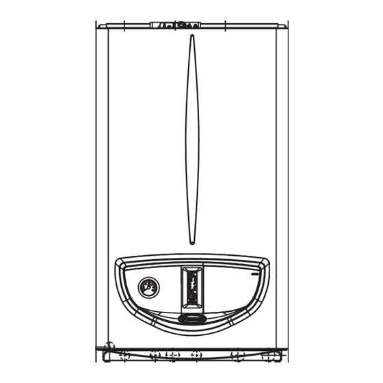
1.2 MAIN DIMENSIONS.
Height
(mm)
781
CONNECTIONS
DOMESTIC
GAS
HOT WATER
G
3/4"
1/2"
Fig. 1-1
The plugs (standard supply) are to be used only in
conjunction with the mounting brackets or fixing
template to fix the appliance to the wall; they only
ensure adequate support if inserted correctly
(according to technical standards) in walls made
of solid or semi-hollow brick or block. In the
case of walls made from hollow brick or block,
partitions with limited static properties, or in any
case walls other than those indicated, a static test
must be carried out to ensure adequate support.
N.B.: the hex head screws supplied in the blister
pack are to be used exclusively to fix the relative
mounting bracket to the wall.
These boilers are used to heat water to below
boiling temperature in atmospheric pressure.
They must be attached to a heating system sui-
table for their capacity and voltage.
Key:
Width
Depth
AC - Domestic hot water outlet
(mm)
(mm)
ACV - Solar valve kit DHW inlet (Optional)
440
340
AF - Domestic cold water inlet
M - System flow
SYSTEM
AC
AF
R
M
N .B.: connection group (optional)
1/2"
3/4"
3/4"
Fig. 1-2
G - Gas supply
R - System return
V - Electrical connection
ES
PT
GR
CZ
HU
IE
143
Advertisement
Table of Contents

Related Manuals for Immergas Maior Eolo 24 4E


Summary of Contents for Immergas Maior Eolo 24 4E
-
Page 1: Boiler Installation
Only professionally qualified heating/plumbing compartments under the responsibility of technicians are authorised to install Immergas each individual building and only accessible gas appliances. Installation must be carried out to the user (technical compartments and the... -
Page 2: Anti-Freeze Protection
(technical specifications). (e.g. the Immergas After-Sales Technical Assistance - protect the central heating circuit from free- The coupling system must conform to standards. Service). The power cable must be laid as shown. -
Page 3: External Probe (Optional)
Comando Amico Remoto remote control are available as optional kits. On/Off chrono-thermostat electrical con- All Immergas chrono-thermostats are connec- nections (Optional). The operations described ted with 2 wires only. Carefully read the user below must be performed after having removed and assembly instructions contained in the the voltage from the appliance. -
Page 4: Immergas Flue Systems
Important: The boiler must only be installed element. This will ensure sealing efficiency of together with an original Immergas air intake • Configuration type B, open chamber and fan the coupling. and flue gas exhaust system. This system can be assisted. - Page 5 Fig. 1-11 Fig. 1-12 The cover kit includes: N° 1 Heat moulded cover N° 1 Gasket clamping plate N° 1 Gasket N° 1 Gasket clamp N° 1 N°1 Intake hole covering plate The terminal kit includes: N° 1 Gasket N° 1 Exhaust flange Ø 80 N°...
- Page 6 Shutter regulation table Maior Eolo 24 4E. Flue gas shutter notch Type of installation (duct length in metres) Ø 60/100 horizontal concentric kit Da 0 a 0,5 Da 0,5 a 1,5 Da 1,5 a 3,0 Ø 60/100 vertical concentric kit Da 0 a 2,2...
- Page 7 Tables of Resistance Factors and Equivalent Lengths. Equivalent Equivalent Equivalent length in m of length in m of concentric length Resistance concentric pipe pipe in m of pipe DUCT TYPE Factor Ø 60/100 Ø 80/125 Ø 80 Concentric pipe Ø 60/100 m 1 Intake m 7,1 Intake and m 2,8 Exhaust 16,5...
-
Page 8: Indoor Installation
1.9 INDOOR INSTALLATION. • Application with side outlet (Fig. 1-18); Using Important: if the exhaust terminal and/or exten- • Type C configuration, sealed chamber and the horizontal intake-exhaust kit, without the sion concentric pipe needs shortening, consider fan assisted. special extensions, enables routing through that the internal pipe must always protrude by a wall thickness of 724 mm with the left side 5 mm with respect to the external pipe. - Page 9 The kit includes: N°1 - Gasket (1) N°1 - Concentric bend Ø 60/100 (2) N°1 - Adapter Ø 60/100 for Ø 80/125 (3) N°1 - Int./exhaust concentric terminal Ø 80/125 (4) N°1 - Internal white wall sealing plate (5) N°1 - External grey wall sealing plate (6) Fig.
- Page 10 • Extension pipes and elbows push-fittings. To • Extensions for the separator kit Ø 80/80. The • Temperature loss in flue ducts. To prevent install push-fitting extensions with other ele- max. vertical straight length (without bends) problems of flue gas condensate in the exhaust ments of the flue extraction elements assembly, that can be used for Ø 80 intake and exhaust pipe Ø 80, due to flue gas cooling through the...
- Page 11 2 metres. the flat-tipped hex screws included in the kit. intake pipes, on request Immergas supplies • Configuration type B, open chamber and fan Remove the flat flange present in the lateral hole insulated intake-exhaust pipes.
- Page 12 1.10 FLUE EXHAUST TO FLUE/CHIMNEY. 1.14 GAS SYSTEM START-UP. Flue gas exhaust does not necessarily have to be To start up the system proceed as follows: connected to a branched type traditional flue. - open windows and doors; The flue exhaust can be connected to a special - avoid presence of sparks or naked flames;...
-
Page 13: Circulation Pump
1.16 CIRCULATION PUMP. Pump release. If, after a prolonged period of By-pass regulation (part. 25 Fig. 1-34). If neces- The boilers are supplied with a built-in circula- inactivity, the circulation pump is blocked, sary, the by-pass can be regulated according to tion pump with 3-position electric speed control. -
Page 14: Kits Available On Request
(Fig. 1-8). For indoor installations, type separate adjustments and to keep water flow B configuration, a suitable top protection cover rate high for each zone, Immergas supplies zone coupled with the flue exhaust kit must be fitted. system kits on request. -
Page 15: Cleaning And Maintenance
- USER appliance and on completion of operations ensure that a qualified technician checks efficiency of the INSTRUCTIONS FOR USE ducting or other devices. AND MAINTENANCE Never clean the appliance or connected parts with easily flammable substances. 2.1 CLEANING AND MAINTENANCE. Never leave containers or flammable substances Important: the heating systems must undergo in the same environment as the appliance. -
Page 16: Using The Boiler
• “Stand-by” mode. Press button (3) until the technician for assistance (e.g. Immergas After- system is sufficient to heat the radiators, the Sales Technical Assistance Service). -
Page 17: Boiler Shutdown
Block due to loss of continuous flame signal anomaly or incongruency on the electric wiring, freeze liquid and installation of the Immergas the boiler will not start. If normal conditions are This occurs if the “Flame signal loss” error Anti-freeze Kit in the boiler (Par. -
Page 18: Hydraulic Diagram
- TECHNICIAN - switch the boiler on and check correct ignition; - check sealing efficiency of water circuits; BOILER - make sure the gas maximum, intermediate - check ventilation and/or aeration of the instal- and minimum flow rate and pressure values lation room where provided. -
Page 19: Wiring Diagram
3.3 TROUBLESHOOTING. components and ensure correct installation of N.B.: Maintenance must be carried out by a the terminal. qualified technician (e.g. Immergas Technical - Frequent interventions of the over heating After-Sales Assistance Service). safety thermostat. It can depend on reduced - Smell of gas. -
Page 20: Information Menu
3.4 INFORMATION MENU. To exit the menu, press the “Summer/Winter” Pressing the “Summer/Winter” button (4) for 4 button (4) again for 4 seconds or wait for 120 seconds, the “Information menu” is activated, seconds. which allows to display some boiler functioning With the menu active on the indicator (17) the parameters. - Page 21 Range Parameter Parameter Description Default (ref. 21 Fig. 2-1) (ref. 17) Establishes the switch-off method in DHW mode. 0 Correlated: the boiler switches off on the basis of the temperature set. DHW thermostat 0 - 1 1 Fixed: the switch-off temperature is fixed on the maximum value independently from the value set on the control panel.
-
Page 22: Converting The Boiler To Other Types Of Gas
Boiler conversion must be carried out by a - The pressure to which the boiler maximum qualified technician (e.g. Immergas After-Sales 3.8 POSSIBLE ADJUSTMENTS heat output must be adjusted in central Technical Assistance Service). -
Page 23: Three-Way Anti-Block Function
3.10 “CHIMNEY SWEEP” FUNCTION. 3.15 SOLAR PANELS COUPLING - Check that, after discharging system pressure When activated, this function forces the boiler FUNCTION. and bringing it to zero (read on boiler manome- to variable output for 15 minutes. The boiler is set-up to receive pre-heated water ter), the expansion vessel factory-set pressure In this state all adjustments are excluded and only from a system of solar panels up to a maximum... -
Page 24: Casing Removal
3.17 CASING REMOVAL. 3 Loosen the 2 front screws (b) for fixing the To facilitate boiler maintenance the casing can be casing. completely removed as follows: (Fig. 3-4 / 3-5): 4 Loosen the 2 lower screws (b) for fixing the 1 Unhook the decorative frame (a) from the casing. - Page 25 Fig. 3-5...
-
Page 26: Variable Heat Output
1013 mbar. Burner pressure values The adjustments should therefore, be carried sure test. The power data in the table has been refer to use of gas at 15°C. Maior Eolo 24 4E. METHANE (G20) BUTANE (G30) PROPANE (G31) -
Page 27: Combustion Parameters
1,30 1,86 18,9 0,97 4,00 40,8 0,95 5,35 54,5 3.19 COMBUSTION PARAMETERS. Maior Eolo 24 4E Gas nozzle diameter 1,35 0,79 0,79 Supply pressure mbar (mm H 20 (204) 29 (296) 37 (377) Flue flow rate at nominal heat output... -
Page 28: Technical Data
3.20 TECHNICAL DATA. Maior Eolo 24 4E Maior Eolo 28 4E Maior Eolo 32 4E Nominal heat input kW (kcal/h) 25,8 (22194) 29,7 (25536) 34,2 (29433) DHW minimum heat input kW (kcal/h) 8,1 (6968) 9,6 (8279) 12,2 (10524) CH minimum heat input... - Page 30 This instruction booklet is made of ecological paper Cod. 1.028662 Rev. 15.031977/000 - 02/10...