Table of Contents
Advertisement
Advertisement
Table of Contents

Related Manuals for MAGINON WK 1


Summary of Contents for MAGINON WK 1
-
Page 3: Preface
1. Contents of box Carefully unpack camera and check that all of the following components are contained in the box: MAGINON® WK 1 wildlife / surveillance camera 4 GB SDHC memory card 8 batteries, type LR6 (AA) Tree fi xing with battery compartment... -
Page 4: Table Of Contents
2. Contents PREFACE 1. INTRODUCTION AND CONTENTS OF BOX 2. CONTENTS 3. HAZARD, SAFETY AND WARNING NOTICES 4. INTRODUCTION 5. YOUR CAMERA 5.1. Front view 5.2. View from below 5.3. View from rear 5.4. Power supply 5.5. Installation of tree fi xing and battery compartment 5.6. - Page 5 9. CONFIRMITY 10. CARE 11. STORAGE 12. DISPOSAL 13. POTENTIAL LEGAL INFRINGEMENTS 14. WARRANTY AND SERVICE 15. TECHNICAL DATA 16. INDEX...
-
Page 6: Hazard, Safety And Warning Notices
3. Hazard, safety and warning notices Incorrect use of the camera and accessories can be dangerous for you and others and can damage or destroy the camera. We therefore ask you to read and strictly observe the following Hazard, safety and warning notices. Intended use ... - Page 7 Danger from heat - fi re hazard Do not leave camera in places that are susceptible to considerable increases in temperature (e.g. a vehicle). The housing and internal parts may be damaged, which in turn could cause a fire. ...
- Page 8 Do not operate camera whilst running or driving. You could fall or cause a traffic accident. Only use a power supply (not supplied) with the input voltage (6V, min. 500 mA) specified on the rating plate. No liability shall be accepted for damage caused by the use of an incorrect power supply.
-
Page 9: Introduction
4. Introduction The MAGINON® WK 1 is a wildlife and surveillance camera with a 3-zone infrared sensor detecting sudden changes in ambient temperature within an evaluation area. The signals of the highly sensitive PIR (passive infrared sensor) activate the camera, triggering photo or video recordings. -
Page 10: Your Camera
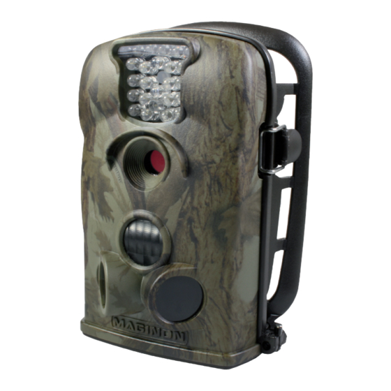
5. Your camera 5.1. Front view Infrared LED light Light sensor Motion display Lens Central sensor zone Side sensor zones (Passive Infrared Sensors, Lock for base PIR) fl ap Hole for lock... -
Page 11: View From Below
5.2. View from below Battery department cover Push to open and close battery compartment TV out connection DC in socket On/Off / SD card slot USB socket Test switch Base fl ap Pull to open base fl ap Under the base fl ap, the camera has the following connections and operating elements: ... -
Page 12: View From Rear
5.3. View from rear Contacts TFT LCD Closing latch display Operating Compartment buttons for 4 additional batteries Battery box Retaining bolt Note: • Caution! Do not touch or even short-circuit the connecting contacts between camera and battery box! 5.4. Power supply As a power supply we recommend the use of four new high-performance alkaline 1.5V LR6 (AA) batteries or rechargeable Ni-MH batteries with low self discharge (not supplied). -
Page 13: Installation Of Tree Fi Xing And Battery Compartment
5.5. Installation of tree fi xing and battery compartment If you wish to operate the camera with the maximum number of 8 batteries, insert 4 batteries in the provided battery compartment prior to securing the tree fi xing. For this purpose open the protective battery cover of the tree fi xing by slightly pushing up the safety lever (S) before pulling it out. - Page 14 Push the closing latches (4) on the side of the tree fi xing forwards until they are positioned in the provided recess (5) of the camera. To secure, fully pull back black safety catch (6). Insert retaining bolt into rear of tree fi xing and tighten. Use the supplied mounting strap to secure camera to a tree or other objects.
-
Page 15: Using The Wall Bracket
5.6. Using the wall bracket Using the supplied wall bracket the camera can be secured to walls or ceilings. Prior to securing the wall bracket, ensure that all bolts have been securely tightened. Note: • Before drilling, check that no cables are installed in the wall! Hold the base of the wall bracket against the intended place of installation and mark the position of the holes to be drilled (A). -
Page 16: Quick Start Introductions
6. Quick start instructions 6.1. Inserting batteries Observe the following when inserting the batteries. • Open the cover on the base by opening the catch and folding open the cover (see page 15). • Push on the cover of the battery compartment and release again. The cover opens. -
Page 17: Inserting The Memory Card
6.2. Inserting the memory card The camera does not have any internal storage and does therefore not operate without an inserted SD/SDHC memory card. Prior to inserting the memory card into the card slot, ensure that the write protection switch on the side of the memory card is not in the “Lock”... -
Page 18: Locking The Base Fl Ap
The memory card should only be inserted or removed with the camera switched off . If the memory card is inserted or removed when the camera is switched on, the camera switches off automatically. Note: • Please note that the camera cannot be switched on until a SD/SDHC memory card has been inserted. -
Page 19: Setting Up The Test Mode
In the video mode the length of the manually fi lmed videos is not limited. • Push the button to select the menu language of the MAGINON® WK 1 camera if the menu is not activated. The selected language is briefl y shown on the display in red. -
Page 20: Aligning The Camera
• Press the OK/REPLAY button to select the playback mode. Videos and photos can be played back on the camera LCD or a connected TV monitor. By pressing the OK/ REPLAY button again you return from the playback mode to the recording mode. Use the ... -
Page 21: Night Photos/Video Recordings
• If the blue LED on the front of the camera lights up, your movement has been detected by one of the side sensor zones. • If the red LED on the front of the camera lights up, your movement has been detected by the central sensor zone. -
Page 22: Live Mode Set-Up
The MAGINON® WK 1 uses IR LEDs with a long wavelength in order to keep the proportion of red light as low as possible. The existing number of IR LEDs provides a high light beam angle and thus allows night photos/video recordings to be taken at a distance of between approx. -
Page 23: Advantages Of Pir Sensors (Passive Infrared Sensors)
This problem is solved by the unique design of the side PIR sensor zone of the MAGINON ® WK 1. By combining the two side sensor zones and the central zone, an induction angle of 100 to 120o is achieved, an extremely wide range, by far exceeding the 50°... -
Page 24: Settings
8. Settings Prior to using the MAGINON® WK 1, change the settings to suit your requirements. Below is a list of all setting options of the camera. 8.1. Menu settings Slide the Mode switch of the wildlife camera to the TEST position to start the test mode. - Page 25 • Video resolution 640×480, 320×240 Select the required video resolution, 640x480 or 320x 240 pixels. A higher resolution produces higher-quality videos but also larger fi les, taking up more room on the memory card. 640x480 is equal to the VGA mode in the standard format 4:3.
- Page 26 • Timer 1 and timer 2: On/Off Set one of the two timers to ON if the camera should only be activated for a certain period during the day. As soon as you have confi rmed ON by pressing the OK button, a start and end time can be set.
-
Page 27: Data Format
• Side PIR (side sensor zones): On/Off The two side PIR sensor zones provide a wider detection angle and detect more potential triggers. Sometimes you only wish to monitor a certain area. Excessive irrelevant triggering by the side sensor zones outside of this area constantly switches the camera on and off... -
Page 28: Confirmity
9. Confi rmity This device has been tested under Part 15 of the FCC Rules, and it has been con rmed that the tolerance limits for a Class B digital device have been met. These tolerance limits are intended to o er suitable protection against hazardous sources of interference when installed in residential accommodation. -
Page 29: Care
10. Care Do not use any corrosive cleaners, such as mentholated spirits, thinners, etc. to clean the camera housing and camera accessory. When required, clean system components with a soft dry cloth. 11. Storage Always remove batteries (not supplied) from the housing if camera is not being used for some time and store batteries separately. -
Page 30: Potential Legal Infringements
13. Potential legal infringements The following information should be observed when using the camera: Copyright protection In principle everybody has the rights to his/her own image. According to the copy- right law, images may only be published without the permission of the person in- volved if the person is only of secondary importance in an image of the countryside or of another locality. -
Page 31: Warranty And Service
The device comes with a manufacturer´s warranty of 3 years. Please see the enclosed Warranty Card for details. Please contact our hotline prior to returning a defective device. Service address: Manufacturer's address: Sertronics LTD supra MAGINON® Service Foto-Elektronik-Vertriebs-GmbH 45 Regal Drive, Walsall Enterprise Park Denisstr. 28A Walsall, WS2 9HQ 67663 Kaiserslautern United Kingdom Germany Tel.: 00 800 - 78 77 23 68... -
Page 32: Technical Data
15. Technical Data Element Description Image sensor 5.0 mega pixels CMOS sensor Max. resolution 5 mp: 2,560 x 1,920; 12 mp: 4,000 x 3,000 (interpolated) Display 6.1 cm (2.4") color TFT LCD; 480x234 pixels Recording medium Supports SD/SDHC memory cards 1-16 GB (optional) Video resolutions 640 x 480;... -
Page 33: Index
16. Index Front view of camera 8 Areas of application 7 Hazard information 4ff Batteries, inserting 11, 13 Battery compartment 9, 11, 13 Images, number of 23 Battery type 5, 10, 12 Infrared sensors 7, 8, 18ff , 21 Blue LED 18 Installing the tree fi xing 11ff... - Page 34 Time, setting 23 Time stamp 24 Operating buttons 16ff Time-lapse function 24 Timer 24 Tree fi xing 11 Parameter settings 17, 22 Tree strap 7 Passive Infra Red Sensor 17 Password, setting 24 Photo resolution 22 USB 9, 25, 26 Photos 7, 16, 22ff...
- Page 36 supra 90742 Foto-Elektronik-Vertriebs-GmbH Denisstr. 28A 06/2013 67663 Kaiserslautern 2000 7331 Germany...