Table of Contents
Advertisement
Advertisement
Table of Contents

Related Manuals for MAGINON ipc-1


Summary of Contents for MAGINON ipc-1
-
Page 3: Introduction
Dear Customer, Congratulations on purchasing this high quality MAGINON® product. You have chosen a modern security camera with excellent technical features and accessories which are all especially easy to use. Please read all instructions carefully and attentively. Pay special attention to all safety instructions. -
Page 4: Table Of Contents
User data on delivery of IP Security Camera Note: • Please make sure to apply a password to the “admin“ user account, on fi rst use of the camera. User name: admin Password: no Password presetted New Password: _______________________ 2. Table of contents Introduction 1. - Page 5 7. Using the security camera 7.1. Accessing the camera 7.2. Controlling the camera 7.3. Using the camera via mobile devices 7.4. “Maginon IPC Viewer“ App Instructions 8. Conformity 9. Disposal 10. Warranty and Service 11. Technical Specifi cation 12. Glossary...
-
Page 6: Hazard, Safety And General Warnings
3. Hazard, safety and general warnings Improper use or treatment of the camera and accessories poses a risk to you and others, and the camera may be damaged or destroyed. Therefore please read and observe strictly the following hazard, safety and general warnings. Intended use ... - Page 7 Hazard of electrocution in case of wet and humid conditions The camera and any supplied components may not be exposed to dripping or spray water. Containers filled with liquid, such as vases or glasses may also not be placed on or close to the camera Danger of fire and electrocution.
- Page 8 Damage from heat – fi re hazard Do not leave camera and receiver in places that are susceptible to considerable increases in temperature (e.g. in a vehicle). The housing and internal parts may be damaged, which in turn could cause a fire. ...
-
Page 9: Preparations
4. Preparations 4.1. Description of parts 1. MAGINON IP Security Camera IPC-1 6. Assembly kit (not shown) 2. Mounting bracket 7. Software CD (not shown) 3. Network cable 8. Instruction manual (not shown) 4. AC adaptor 9. Warranty documents (not shown) -
Page 10: Views Of The Camera
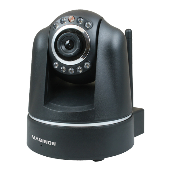
4.2. Views of the camera 90° 270° 1. Lens 5. Network socket (LAN) 2. Infrared LED 6. Alarm socket (in/out) 3. Sensor 7. Power supply socket (5V DC) 4. WiFi antenna 8. Reset button... -
Page 11: Installing The Security Camera
4.3. Installing the security camera The IP security camera can be installed in a fi xed location using the stand supplied. Note: • The security camera should not be installed directly beside electronic equipment as this may result in interference. Should you experience picture interference, test the camera in a diff... - Page 12 4.3.3. Completing the camera installation Connect the camera to the power supply and, fi nally, plug the power supply into an electri- cal power socket.
-
Page 13: Installing The Security Camera
5. Installing the security camera 5.1. System requirements Operating system: the software contained on the CD supplied is only suitable for Windows systems. However, browser access may be used to set up and control the IP security camera via Mac OS, Linux or other operating systems also. Operating systems: Windows 2000 (SP 4), Windows XP (SP 2), Vista, 7, 8 Processor:... -
Page 14: Installing The Software
5.3. Installing the software Insert the software CD supplied into your computer’s CD/DVD drive. The selection menu shown below should then appear. In the event that the menu does not launch automatically, go to the drive overview on your computer and click on the CD/DVD drive icon. To launch, double click on the CDMenu/CDMenu.exe program. -
Page 15: Setting Up The Security Camera
5.4. Setting up the security camera Make sure that the security camera is connected to both the router and the power source. Then open the program supra IPCam Con g. Within the program, go to “Start search” to display a list of available security cameras. From the list, select the camera you want to set up or select. - Page 16 The camera is installed automatically on the network providing the “Use DCHP” option is activated and the router being used also supports DHCP (and this is activated). However you can also specify the network data manually if, say, automatic confi guration does not work. If the port being used by the security camera has to be changed, specify the new port number.
-
Page 17: Installing Under Mac Os
IP address. Once you have this you can then access your router’s confi guration screen. Next, you will need the security camera’s IP address from the settings information. This address then allows the IPC-1 confi guration screen to be opened and the camera settings to be programmed. - Page 18 Now switch to the “TCP/IP” screen and you’ll fi nd your router’s IP address under “Router”. In the example below, the IP address is 192.168.16.1. Establishing the security camera‘s IP address Now open the Safari web browser and enter your router’s IP address in the “go to” window. This will open the router’s confi guration screen which will generally include a clickable option called “DHCP table”...
- Page 19 Please note that your router’s confi guration screen layout may diff er from our example. This list includes the security camera described as “ipcam_xxx” (“ipcam_006E060241B6” in the example above). Next to this is the camera’s IP address (in this instance 192.168.1.113). Enter this address in a new browser window (Safari) to open the camera’s confi guration screen.
-
Page 20: Internet Access
5.6. Internet access To be able to access the security camera over the Internet you will fi rst need the camera’s Internet address (public IP address). You have four diff erent ways of fi nding out the relevant IP address. If a separate Internet address (domain) has been registered for the camera (see Section 6.8., DDNS Settings), this can be used to access the camera. - Page 21 Start by opening your router’s port forwarding menu. In the example shown, two security cameras are connected to the router, one called IPCamera1 under local network address 192.168.1.110 and one called IPCamera2 under local network address 192.168.1.111. External port 81 is now specifi ed as the access point for IPCamera1. TCP and UDP are both permitted protocols, however the only one required is TCP.
-
Page 22: Settings
6. Settings The following sections will give you an overview of all possible settings for your IP security camera. Should problems arise, or settings need to be altered, during installation or use, you will fi nd advice here on the relevant options available to you. Bring up the camera on your Internet browser (see Section 7.1.) and log on via a user account with administrator’s permissions. -
Page 23: Camera Name
6.2. Camera name You can give the camera a name, for example in order to locate it more easily on the network or as a unique identifi er where more than one camera is being used. Enter the camera’s chosen name in the text fi eld, then click “Save”. The camera name may consist of any characters and may be up to 20 characters long. -
Page 24: Date And Time
6.3. Date and time Specify here which time zone the camera is in and whether the date and time are to be updated automatically via a so called NTP server (time server). Current date and time: this shows the date and time as stored in the camera. This information is synched with the local system when the date and time settings are saved. -
Page 25: User Accounts
6.4. User accounts Up to 8 user accounts may be set up for the security camera. These user accounts are then used to access the security camera. The security camera is shipped with the user account “admin” (no password required). This account can neither be deleted nor have its administrator rights changed. -
Page 26: Network Settings
6.5. Network settings To connect the security camera to an existing network or router, the network settings must be made. Use DHCP: if your network allows a new device (client) to be connected automatically, tick this box. All necessary data will then be drawn directly from the server or router. Web interface port: connections within a network are handled via so called ports allowing the server and each device (client) attached to it to work via diff... - Page 27 In the event that automatic connection of new devices is not supported, please untick the “Remove DHCP” box. This will open up several new input fi elds into which you should enter your network’s access data directly. The data required here can generally be obtained by looking at the network properties on your computer or by asking your network administrator...
-
Page 28: Wireless Settings
6.6. Wireless settings In the event that the security camera is to be connected to a network via a wireless LAN (WiFi) you can enter the relevant settings here. Use WiFi: tick this box if you wish to connect wirelessly to the network. All subsequent required data regarding the wireless network is contained within the router or access point being used to control this network. - Page 29 Encryption: on wireless networks data is mainly encrypted in order to prevent access by third parties. Specify here which type of encryption is used by your wireless network. The setting “Non encrypted” means that data will be transmitted without encryption. If one of the “WEP”, “WPA”...
-
Page 30: Upnp Settings
6.7. UPNP settings Universal Plug & Play (UPnP) allows diff erent manufacturers’ devices to be addressed over an IPbased network. Where UPnP is supported by the router and activated, the required fi rewall settings are made automatically by it. Mark “Use UPNP” where UPNP is to be used for connecting to the security camera. By default, “Use UPNP”... -
Page 31: Ddns Settings
6.8. DDNS settings The security camera can be contacted via the IP address used by the router or server to connect to the Internet. Because, in many instance, the IP address of the Internet connection point is constantly changing, it is benefi cial for the camera to be able to be reached at the same address all the time. - Page 32 Once the camera has been registered successfully, switch to the DDNS settings. For “User name” and “Password”, enter the same data you entered when registering on the DDNS server. In the “Domain name” text fi eld, enter the name you specifi ed upon registration. In the case of one camera only, this is generally the user name, and in the case of more than one registered camera you should use the name you received upon registration.
-
Page 33: Email Settings
6.9. Email settings In response to given events, the security camera can send an alarm message by email. This requires details to be entered on an email account from which emails can be sent. You can use a private email address or set up a separate email address specially for the security camera. - Page 34 Server: enter the address of the SMTP server for the email account. Port: enter the port of the SMTP server. The standard value here is 25. Encryption: specify whether (and which type of ) encryption is used by the SMTP server. ...
-
Page 35: Ftp Settings
6.10. FTP settings The security camera off ers you the opportunity to upload images to an FTP server, on either a one time or a regular basis. Enter here the required access data for an FTP server to be used for this purpose. - Page 36 Path: enter the path under which the images should be stored on the FTP server. Transfer mode: choose whether an active or passive FTP connection should be requested when transmitting. Upload at intervals: tick this option if you would like images from the security camera to be uploaded to the FTP server at regular intervals.
-
Page 37: Alarm Settings
6.11. Alarm settings The security camera can issue alarm messages in a variety of situations. Specify here the conditions under which the camera is to issue an alarm message and what should be undertaken in the event of an alarm. ... - Page 38 Report at digital output: where this option is activated, an alarm message is forwarded via the digital output as soon as it is in existence within the security camera. Alarm level: specify whether the alarm is to be sounded at the digital output as a result of voltage (high setting) or when the voltage disappears (low setting).
-
Page 39: Head Settings
6.12. Head settings This category can be used to make settings aff ecting the positioning of the camera head. Use Infrarot LEDs in darkness: if this option is activated, the infrared LEDs will be cut in as an additional light source in darkness. ... -
Page 40: Resetting
Automatic speeds: specify, separately for up/down/left/right, how fast the camera head should move when being controlled automatically. Click “Save” to accept the changed settings. The new head settings are accepted without rebooting the camera 6.13. Resetting To reset the security camera to factory settings, click “Reset now”. Resetting takes approximately 1 minute. -
Page 41: Using The Security Camera
7. Using the security camera 7.1. Accessing the camera Begin by opening your browser program (Internet Explorer, Firefox, Opera, Google Chrome, Safari or similar). In the address line, enter the IP address of the security camera. If you wish to access the camera from a com- puter on the same local network, you may also enter the local network address. -
Page 42: Controlling The Camera
7.2. Controlling the camera The security camera is controlled by a variety of buttons and options. Below the camera image you will fi nd buttons for exercising direct control over the direction of the camera head as well as some fundamental camera settings. Which buttons are available and which settings may be changed depend on the permissions granted to the user account. - Page 43 The centre (red) button may be used to move the camera to the centre. Press and hold the button until the camera head stays in a middle position. This can take up to 30 seconds, depending on the initial position. For further information on the camera head’s speed of movement, please refer to Section 6.12.
-
Page 44: Camera Image Settings
7.2.3. Camera image settings Use this view to specify the settings pertaining to the came image (picture). Resolution: here you can choose whether the security camera image is displayed in resolution of 640 x 480 pixels or 320 x 240 pixels. ... -
Page 45: Using The Camera Via Mobile Devices
7.3. Using the camera via mobile devices The security camera image may also be accessed using mobile devices such as smartphones or tablet PCs. Use the mobile device’s browser to go to the camera’s homepage and use the mobile device access point below the log on fi elds. Enter your user name and password (where relevant) and log onto the camera. - Page 46 Further camera settings are not possible via mobile devices but may only be made using a PC based browser. You can download and install a free application „Maginon IPC Viewer“ via “App Store” and “Google Play” which will allow you to obtain a live picture of your “Maginon Surveillance...
-
Page 47: Maginon Ipc Viewer" App Instructions
7.4. “Maginon IPC Viewer” App Instructions The “Maginon IPC Viewer” app allows you to access one or more Maginon IPC-1 security cameras via your iPhone or Android smartphone while on the move (where cameras are con- nected to the Internet). As well as managing the settings for several cameras, you also have access to the live image feed and can change the directions the cameras are pointing in. - Page 48 Add a new camera From the summary view, click , to add a new camera to the program. This opens a screen for entering the relevant camera data. Enter the following General information: Name: Enter your chosen name for the new camera. This name is just for identification purposes where more than one camera is being managed.
- Page 49 You have the choice of two methods of connection: Manual: Select “Manual” if you wish to enter the new camera’s IP address and port directly. Then enter this data further down the page under “Manual configuration”. Dynamic: Where a fixed Internet address has been set up for the new camera (see Section “6.8.
- Page 50 Select camera To select one of the listed cameras for purposes of displaying or amending data, touch the relevant entry on the screen. This opens a preview complete with camera image, amendment information and data on the selected camera. takes you from the preview back to the camera list.
-
Page 51: Delete Camera
Amend camera You can amend a camera’s settings at any time by selec- ting “Amend” in the preview. This takes you to the settings described in the “Add a new camera” section. After amending one or more settings, this may be stored using the “Save”... -
Page 52: Conformity
8. Confi rmity This device has been tested in accordance with Part 15 of FCC Regulations, and it has been con rmed that the limits applicable to Class B digital devices have been met. These limits are intended to o er reasonable protection against harmful sources of interference when installed in residential premises. -
Page 53: Disposal
For details please refer to the separate warranty card (enclosed). Before sending in your defective equipment, please contact our hotline. Manufacturer’s address: Service address: Sertronics LTD supra MAGINON® Service Foto-Elektronik-Vertriebs-GmbH 45 Regal Drive, Walsall Enterprise Park Denisstr. 28A Walsall, WS2 9HQ 67663 Kaiserslautern... -
Page 54: Technical Specifi Cation
11. Technical Specifi cation Model IPC-1 Image sensor 1/5" megapixel CMOS sensor, 640x480 pixels Lens F=2.4, f=3.6 mm, infrared lens Infrared light 9 infrared LEDs Night vision Minimum illumination 0.5 Lux (excl. LEDs) Image angle 60° Supported protocols HTTP, FTP, TCP/IP, SMTP, DHCP, DDNS, UPnP WiFi standards IEEE 802.11 b/g... -
Page 55: Glossary
12. Glossary AC adaptor 7 Email settings 31 Access camera 39 Encryption 27 Accessories 1, 7 Administrator 23 Firewall 18 Alarm connection 8 FTP settings 33 Alarm settings 35 FTP server 33 Alarm transmitter 7, 35, 36 Hardware installation 11 Brightness 42 Hazard warnings 4ff... - Page 56 Network connection 8 Tablet PC 43 Network data 13 Technical Specifi cation 52 Network set up 14, 24ff Time 22 Network cable 7, 11 Time zone 22 Network name 26 NTP server 22 Uploading images 33 UPnP 28 Operator 23 User accounts 23 Patrolling 40 Visitor 23...
- Page 58 supra Foto-Elektronik-Vertriebs-GmbH 90577 Denisstr. 28A 03/2013 67663 Kaiserslautern 2000 5696 Germany...