
Related Manuals for York YLUA Series


Summary of Contents for York YLUA Series
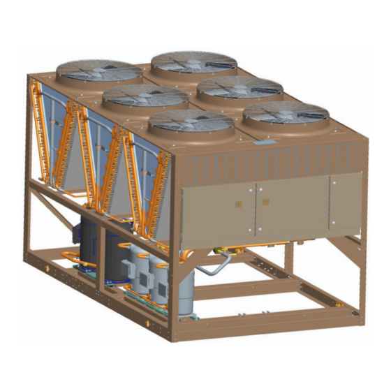
- Page 1 FORM 150.63-EG4 (1012) Model YLUA Air-Cooled Scroll Compressor Condensing Units Style A 70 – 135 TON 245 – 475 kW R-410A 50 Hz...
-
Page 2: Table Of Contents
Isolator Details ........................................... 28 Isolator Locations ........................................31 Electrical Notes.......................................... 33 Electrical Data ..........................................34 Electrical Drawings ........................................36 Application Data ........................................46 Guide Specifications ......................................... 47 0308 Design Series YL=York Scroll Type Start X=Across-the-Line Voltage Code Unit 50=380/415-3-50 Condensing Refrigerant E= R-410A... -
Page 3: Introduction
Introduction Model YLUA Air-Cooled Scroll Compressor Condensing Units Style A YORK Air-Cooled Scroll Condensing Units are the perfect refrigeration com ponents for all air conditioning applications that use DX central station air han dling. They are designed for outdoor (roof or ground level) installation. Each unit includes hermetic scroll compressors, air cooled condensers, and a weather resistant microprocessor control center, all mounted on a formed steel base. -
Page 4: Unit Overview
FORM 150.63-EG4 (1012) Unit Overview GENERAL design in both the axial and radial direction. All rotating parts of the compressors are statically and dynamically The 68-135 Ton (238 - 473 kW) YLUA Condensing Unit balanced. A large internal volume and oil reservoir pro- Models are shipped complete from the factory ready for vides greater liquid tolerance. -
Page 5: Microcomputer Control Center
FORM 150.63-EG4 (1012) Microcomputer Control Center All controls are contained in a NEMA 3R cabinet with • An RS-232 port, in conjunction with this press-to-print hinged and gasketed outer door and includes: button, is provided to permit the capability of hard copy print-outs via a separate printer (by others). - Page 6 FORM 150.63-EG4 (1012) Microcomputer Control Center - continued • Discharge Air Temperature Reset via a YORK The operating program is stored in non-volatile memory ISN DDC or Building Automation System (by oth (EPROM) to eliminate chiller failure due to AC powered ers) via: failure/battery discharge.
-
Page 7: Accessories And Options
FORM 150.63-EG4 (1012) Accessories and Options POWER OPTIONS: can be directly connected to a YORK Building Automated System via the standard on board RS485 communication COMPRESSOR POWER CONNECTIONS – Single-point port.) terminal block connection(s) are provided as standard. The following power connections are available as options. - Page 8 FORM 150.63-EG4 (1012) Accessories and Options - continued PRE-COATED FIN CONDENSER COILS – The air-cooled LOUVERED PANELS (CONDENSER COIL ONLY) – Lou- condenser coils are constructed of black epoxy-coated vered panels are mounted on the sides and ends of the aluminum fins.
-
Page 9: Selection Data
FORM 150.63-EG4 (1012) Selection Data The ratings shown on pages 12 through 17 are based and using data supplied by the evaporator manufacturer, on unit operation in a well designed and properly piped enter the ratings tables and select a unit to meet the system. - Page 10 FORM 150.63-EG4 (1012) Selection Data - continued REFRIGERANT PIPING To allow adequate oil return to the compressor, suction risers should be sized for a minimum of 1000 FPM (5.08 General – When the unit has been located in its final m/s) while the system is operating at minimum capacity position, the unit piping may be connected.
- Page 11 FORM 150.63-EG4 (1012) TABLE 1 - FITTING EQUIVALENT LENGTHS YCUL Short Radius Ell Long Radius Ell 3/4" (19mm) 6.5ft. (2m) 4.5 ft.(1.4m) 7/8" (22mm) 7.8 ft. (2.4m) 5.3 ft (1.6m) 1-1/8" (29mm) 2.7ft. (.8m) 1.9 ft. (.6m) 1-3/8" (35mm) 3.2 ft. (1m) 2.2 ft.
- Page 12 FORM 150.63-EG4 (1012) Selection Data - continued TABLE 4 – REFRIGERANT LINE CONNECTIONS Suction Line Liquid Line Refrigerant Line Connection Model System Velocity @ Tons Copper Nominal Copper Number Number Nominal Type L Tons Type L Capacity in inches OD Unloaded inches OD Suction...
- Page 13 FORM 150.63-EG4 (1012) INTENTIONALLY LEFT BLANK JOHNSON CONTROLS...
-
Page 14: Ratings 50Hz English
FORM 150.63-EG4 (1012) Ratings 50Hz English MODEL: YLUA0248YE AIR TEMPERATURE ON - CONDENSER (°F) 75.0 80.0 85.0 90.0 95.0 LCWT (°F) TONS TONS TONS TONS TONS 35.0 65.1 47.9 14.3 63.4 50.7 13.2 61.6 53.7 12.2 59.7 57.0 11.2 57.7 60.4 10.3 37.0... - Page 15 FORM 150.63-EG4 (1012) MODEL: YLUA0248YE AIR TEMPERATURE ON - CONDENSER (°F) 100.0 105.0 110.0 115.0 LCWT (°F) TONS TONS TONS TONS 35.0 55.4 63.9 53.1 67.5 50.6 71.2 48.2 75.2 37.0 57.4 64.3 55.0 67.9 52.5 71.7 50.0 75.7 39.0 59.5 64.8 10.0...
- Page 16 FORM 150.63-EG4 (1012) Ratings 50Hz English - continued MODEL: YLUA0308YE AIR TEMPERATURE ON - CONDENSER (°F) 75.0 80.0 85.0 90.0 95.0 LCWT (°F) TONS TONS TONS TONS TONS 35.0 78.6 55.4 14.4 76.5 58.5 13.4 74.4 61.7 12.4 72.1 65.3 11.5 69.8 69.1...
- Page 17 FORM 150.63-EG4 (1012) MODEL: YLUA0308YE AIR TEMPERATURE ON - CONDENSER (°F) 100.0 105.0 110.0 115.0 LCWT (°F) TONS TONS TONS TONS 35.0 67.1 72.9 64.3 77.0 61.5 81.3 58.6 85.9 37.0 69.6 73.4 10.0 66.7 77.5 63.8 81.8 60.7 86.4 39.0 72.1 73.9...
- Page 18 FORM 150.63-EG4 (1012) Ratings 50Hz English - continued MODEL: YLUA0468YE AIR TEMPERATURE ON - CONDENSER (°F) 75.0 80.0 85.0 90.0 95.0 LCWT (°F) TONS TONS TONS TONS TONS 35.0 117.7 88.7 13.8 114.5 93.4 12.9 111.2 98.5 11.9 107.5 104.4 10.9 103.9 110.5...
- Page 19 FORM 150.63-EG4 (1012) MODEL: YLUA0468YE AIR TEMPERATURE ON - CONDENSER (°F) 100.0 105.0 110.0 115.0 LCWT (°F) TONS TONS TONS TONS 35.0 99.8 116.3 95.6 122.6 91.1 129.4 86.6 136.6 37.0 103.4 117.1 99.0 123.5 94.4 130.3 89.8 137.5 39.0 107.1 118.1 102.5...
-
Page 20: Ratings 50Hz Si
FORM 150.63-EG4 (1012) Ratings 50Hz SI MODEL: YLUA0248YE AIR TEMPERATURE ON - CONDENSER (°C) 25.0 30.0 35.0 40.0 45.0 LCWT (°C) 228.9 49.2 217.5 54.5 205.3 60.6 190.3 66.9 174.8 73.7 236.1 49.5 224.4 54.9 211.8 61.0 196.5 67.3 180.6 74.2 243.5 50.0... - Page 21 FORM 150.63-EG4 (1012) MODEL: YLUA0308YE AIR TEMPERATURE ON - CONDENSER (°C) 25.0 30.0 35.0 40.0 45.0 LCWT (°C) 276.4 56.8 262.8 62.6 248.3 69.2 230.7 76.3 212.4 84.2 285.4 57.2 271.4 63.0 256.5 69.7 238.3 76.7 219.5 84.6 294.6 57.6 280.2 63.4 264.8...
- Page 22 FORM 150.63-EG4 (1012) Ratings 50Hz SI - continued MODEL: YLUA0468YE AIR TEMPERATURE ON - CONDENSER (°C) 25.0 30.0 35.0 40.0 45.0 LCWT (°C) 413.5 91.0 392.7 99.9 369.4 110.7 342.8 121.5 314.4 133.9 426.7 91.8 404.8 100.9 381.4 111.5 353.8 122.3 324.7 134.7...
-
Page 23: Part Load Ratings
FORM 150.63-EG4 (1012) Part Load Ratings YLUA0248YE YLUA0338YE % FULL % FULL COMPR AMBIENT COMPR AMBIENT LOAD TONS UNIT EER LOAD TONS UNIT EER °F °F DISPL. DISPL. 100.0 81.3 54.5 80.0 16.0 100.0 113.0 75.4 80.0 15.9 83.3 68.6 44.9 80.0 15.9... -
Page 24: Physical Data
FORM 150.63-EG4 (1012) Physical Data Model Number YLUA Refrigerant R-410A HIGH EFFICIENCY UNITS 0248YE 0278YE 0298YE 0308YE 0338YE 0408YE 0468YE 0498YE General Unit Data Length (mm) 2948.9 2948.9 2948.9 3624.6 3624.6 3624.6 4767.6 4767.6 Width (mm) 2235.2 2235.2 2235.2 2235.2 2235.2 2235.2 2235.2... -
Page 25: Dimension Drawings
FORM 150.63-EG4 (1012) Dimension Drawings Length Width Height Connection Sizes System 1 Dimensions System 2 Dimensions New Model Suction In 1 / 2 Liquid Out 1 / 2 Suction In Liquid Out Suction In Liquid Out 116.1 88.3 95.3 89.7 43.9 39.6 84.3... - Page 26 FORM 150.63-EG4 (1012) Dimension Drawings - continued S2-IN L2-OUT Length Width Height Connection Sizes System 1 Dimensions System 2 Dimensions New Model Suction In 1 / Liquid Out 1 / Suction In Liquid Out Suction In Liquid Out YLUA0308YE 143.5 88.3 95.3 89.7...
- Page 27 FORM 150.63-EG4 (1012) Length Width Height Connection Sizes System 1 Dimensions System 2 Dimensions New Model Suction In 1 / Liquid Out 1 / Suction In Liquid Out Suction In Liquid Out YLUA0468YE 187.5 88.3 95.3 89.7 43.9 3.1 / 2.7 1.4 / 1.1 41.4 26.5...
-
Page 28: Isolator Details
FORM 150.63-EG4 (1012) Isolator Details ONE INCH DEFLECTION SPRING ISOLATOR CROSS-REFERENCE 5/8" EQUIPMENT BASE (by Others H" C" T" B" L" D" W" MOUNT DIMENSION DATA (INCHES) TYPE 7-3/4 6-1/2 4-3/4 5-5/8 10-1/2 9-1/4 7-3/4 9/16 RATED CAPACITY (FOR UNITS WITH ALL LOAD POINTS LESS THAN 1785 LBS (810 KG)) MODEL NUMBER COLOR CODE... - Page 29 FORM 150.63-EG4 (1012) ELASTOMERIC ISOLATOR CROSS-REFERENCE RD-Style Isolators ELASTOMER DIMENSION DATA (INCHES) MOUNT TYPE 3.13 1.75 1.25 2.38 0.34 0.19 5/16-18 UNC X 3/4 1.25 RD1-WR 3.88 2.38 1.75 3.00 0.34 0.22 3/8-16 UNC X 1 1.75 RD2-WR 5.50 3.38 2.88 4.13 0.56...
- Page 30 FORM 150.63-EG4 (1012) Isolator Details - continued TWO INCH DEFLECTION, SEISMIC SPRING ISOLATOR CROSS-REFERENCE Y2RS 1-1/8” 5/8” 2-3/4” 2-3/4” 3/8” GAP 3/4” TYP. (4) 3/4” 7/8” STOP & 8-3/8” OPER. HEIGHT PART NUMBER ISOLATOR SPRING COLOR WEIGHT RANGE (LBS) WEIGHT RANGE (KGS) Y2RSI-2D-460 GREEN Up thru 391...
-
Page 31: Isolator Locations
FORM 150.63-EG4 (1012) Isolator Locations AVM LOCATIONS YLUA MODEL YLU- 19.5 76.6 1.36 85.5 A0248YE YLU- 19.5 76.6 1.36 85.5 A0278YE YLU- 19.5 76.6 1.36 85.5 A0298YE AVM LOCATIONS YLUA MODEL 117.2 85.5 YLUA0308YE 117.2 85.5 YLUA0338YE 117.2 85.5 YLUA0408YE JOHNSON CONTROLS... - Page 32 FORM 150.63-EG4 (1012) Isolator Locations - continued AVM LOCATIONS YLUA MODEL 69.0 80.0 85.5 YLUA0468YE 69.0 80.0 85.5 YLUA0498YE JOHNSON CONTROLS...
-
Page 33: Electrical Notes
FORM 150.63-EG4 (1012) Electrical Notes NOTES: 1. Minimum Circuit Ampacity (MCA) is based on 125% of the rated load amps for the largest motor plus 100% of the rated load amps for all other loads included in the circuit, per N.E.C. Article 430-24. If the optional Factory Mounted Control Transformer is provided, add the following MCA values to the electrical tables for the system providing power to the transformer: -17, add 2.5 amps;... -
Page 34: Electrical Data
FORM 150.63-EG4 (1012) Electrical Data OVERALL UNIT DUAL POINT ELECTRICAL DATA SINGLE POINT ELECTRICAL DATA SYSTEM 1 SYSTEM 2 CHILLER VOLT MIN DUAL MODEL CODE MIN DUAL MAX DUAL MINIMUM MIN DUAL MAX DUAL MINIMUM MAX DUAL MIN N/F MIN N/F ELEM ELEM FUSE ELEM FUSE... - Page 35 FORM 150.63-EG4 (1012) SYSTEM # 1 SYSTEM # 2 CHILLER VOLT MODEL CODE COMPR 1 COMPR 2 COMPR 3 COMPR 1 COMPR 2 COMPR 3 QTY FLA QTY FLA 0248 19.0 19.0 0278 19.0 19.0 0298 19.0 19.0 0308 19.0 19.0 0338 19.0...
-
Page 36: Electrical Drawings
FORM 150.63-EG4 (1012) Electrical Drawings JOHNSON CONTROLS... - Page 37 FORM 150.63-EG4 (1012) JOHNSON CONTROLS...
- Page 38 FORM 150.63-EG4 (1012) Electrical Drawings - continued JOHNSON CONTROLS...
- Page 39 FORM 150.63-EG4 (1012) JOHNSON CONTROLS...
- Page 40 FORM 150.63-EG4 (1012) Electrical Drawings - continued JOHNSON CONTROLS...
- Page 41 FORM 150.63-EG4 (1012) JOHNSON CONTROLS...
- Page 42 FORM 150.63-EG4 (1012) Electrical Drawings - continued JOHNSON CONTROLS...
- Page 43 FORM 150.63-EG4 (1012) JOHNSON CONTROLS...
- Page 44 THE VOLTAGE TO THESE CIRCUITS IS REMOVED WHEN THE COMMON POINT OF ISOLATION TO THE UNIT IS OPENED. THIS COMMON POINT OF ISOLATION IS NOT SUPPLIED BY YORK. THE YORK VOLTAGE FREE CONTACTS ARE RATED AT 100VA. ALL INDUCTIVE DEVICES {RELAYS} SWITCH BY THE YORK VOLTAGE FREE CONTACTS MUST HAVE THEIR COIL SUPPRESSED USING STANDARD R/C SUPPRESSORS.
- Page 45 FORM 150.63-EG4 (1012) NOTES REFER TO INSTALLATION COMMISIONING OPERATION AND MAINTENANCE MANUAL FOR CUSTOMER CONNECTIONS AND CUSTOMER CONNECTION NOTES, NON COMPLIANCE TO THESE INSTRUCTIONS WILL INVALIDATE UNIT WARRANTY. WIRING AND COMPONENTS FOR COMPRESSOR 3 ONLY FITTED WHEN UNIT HAS 3 COMPRESSORS ON THE SYSTEM.
-
Page 46: Application Data
FORM 150.63-EG4 (1012) Application Data UNIT LOCATION use of spring-type isolators to minimize the transmission of vibration into the building structure. The YLUA Condensing Units are designed for outdoor in- stallation. When selecting a site for installation, be guided Ground Level Installations – It is important that the units by the following conditions: be installed on a substantial base that will not settle, caus- ing strain on the refrigerant lines and resulting in possible... -
Page 47: Guide Specifications
FORM 150.63-EG4 (1012) Guide Specifications PART 1 – GENERAL PART 2 - PRODUCTS 1.01 SCOPE 2.01 CONDENSING UNITS MATERIALS AND COM- PONENTS The requirements of the General Conditions, Supple- mentary Conditions, Division 1, and Drawings apply General: Install and commission, as shown on the to all Work herein. - Page 48 FORM 150.63-EG4 (1012) Guide Specifications - continued valves and liquid line solenoid valves and refrigerant field Programmable Set-points (within Manufacturer piping are supplied by others. limits): display language; suction pressure set- ting and control range, remote reset temperature 2.04 HEAT EXCHANGERS range, set daily schedule/holiday for start/stop, manual override for servicing, low and high Air Cooled Condenser:...
- Page 49 Motor Current Module: Capable of monitoring com- Some accessories and options supercede standard prod- pressor motor current. Provides extra protection uct features. Your YORK representative will be pleased against compressor reverse rotation, phase-loss and to provide assistance. phase imbalance. Options consists of one module per electrical system.
- Page 50 FORM 150.63-EG4 (1012) Guide Specifications - continued coils from incidental damage,visually screen Vibration Isolation (Field Mounted): internal components, and prevent unauthorized Neoprene Pad Isolators. access to internal components. 1 Inch Deflection Spring Isolators: Level adjust- Louvered/Wire Panels: Louvered steel panels able, spring and cage type isolators for mounting on external condenser coil faces, painted as per under the unit base rails.
- Page 51 FORM 150.63-EG4 (1012) JOHNSON CONTROLS...
- Page 52 Printed on recycled paper Form 150.63-EG4 (1012) Supersedes: 150.63-EG4 (1009) © 2012 Johnson Controls, Inc. www.johnsoncontrols.com...