
Related Manuals for Comtrend Corporation GCA-6000


Summary of Contents for Comtrend Corporation GCA-6000
- Page 1 GCA-6000 G.hn Coax Ethernet Adapter User Manual Version A2.1, July 6, 2016 261072-037...
- Page 2 Copyright Copyright©2016 Comtrend Corporation. All rights reserved. The information contained herein is proprietary to Comtrend Corporation. No part of this document may be translated, transcribed, reproduced, in any form, or by any means without prior written consent of Comtrend Corporation.
- Page 3 Protect Our Environment This symbol indicates that when the equipment has reached the end of its useful life, it must be taken to a recycling centre and processed separate from domestic waste. The cardboard box, the plastic contained in the packaging, and the parts that make up this Coax ADAPTER can be recycled in accordance with regionally established regulations.
-
Page 4: Table Of Contents
Table of Contents Chapter 1 Quick Installation ........................... 5 Chapter 2 Introduction ............................9 2.1 Front Panel and LED indicators ........................9 2.2 Bottom Panel .............................. 10 2.3 How to understand the COVERAGE LED colors ..................11 2.4 Point-to-Point Network ..........................12 2.5 Point-to-Multipoint Network ........................ - Page 5 13.3 Factory Reset ............................33...
-
Page 6: Chapter 1 Quick Installation
Chapter 1 Quick Installation Understanding Your G.hn Coax Adapter NOTE: The following steps show how to create or add onto a G.hn Coax Network (A minimum of two G.hn Coax Adapters are required to create a proper connection.) If this is the first time you are setting up a G.hn Coax Network please continue to Section B. ... - Page 7 2. Connect the coaxial cable to the “IN” of the Coax Adapter and to a cable wall outlet. 3. Ensure that your network device is powered on. Connect the Coax Adapter to the LAN port of the network device with an Ethernet cable. Wait for 10 seconds for the Coax Adapter’s Ethernet LED to light up GREEN indicating a stable connection.
-
Page 8: Troubleshooting
Note: Pressing the Config button – located on the side of the device for more than 5 seconds resets the security settings (10 seconds or more performs a factory reset). If you accidentally reset the GCA-6000 unit, repeat step 7 to secure the network. - Page 9 LAN port of the GCA-6000 unit is connected firmly to the LAN port of the other device. To check the condition of the Ethernet cable, use another cable to test the same connection.
-
Page 10: Chapter 2 Introduction
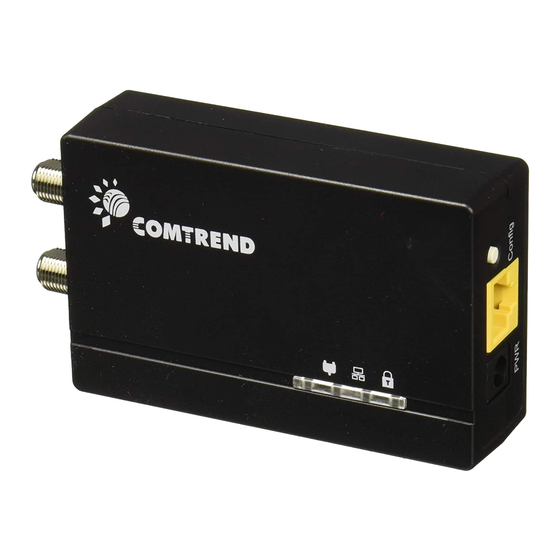
Comtrend’s ITU-T G.hn networking standard compliant Ethernet adapter provides the best quality data transmission at high-speed. The GCA-6000 allows users to extend a local area network via existing coax cables, eliminating the need for extra Ethernet wiring. Installation at home (or in a small office) is quick and easy as plug-and-play technology. -
Page 11: Bottom Panel
Node is secure (it has either received or generated network keys) Security Node is not secure, it has neither received nor generated network key parameters (domain Green name and encryption key) Slow: Device is pairing Blink Fast: Device returning to pairing default settings 2.2 Bottom Panel Item Name Description... -
Page 12: How To Understand The Coverage Led Colors
2.3 How to understand the COVERAGE LED colors The COVERAGE LED displays quality of the network and provides important information that will provide solutions to common questions, such as why a High Definition (HD) movie is not showing or shows with pixels. -
Page 13: Point-To-Point Network
2.4 Point-to-Point Network CASE 1: Estimated throughput is less than 20 Mbps. The Coax channel is not able to transmit an SDTV channel. The COVERAGE LED will be RED as shown in the following figure: CASE 2: Estimated throughput is greater than 20 Mbps but less than 40 Mbps. The coax channel is able to transmit an SDTV channel, but not two SDTV channels simultaneously or one HDTV channel. -
Page 14: Point-To-Multipoint Network
2.5 Point-to-Multipoint Network In the case where the Coax network is composed of three or more adapters, similar situations could arise as with a point-to-point network. CASE 1: The COVERAGE LED in G.hn adapter 2 and G.hn adapter 3 will show the estimated level of the ... -
Page 15: Chapter 3 Log In Procedure
Chapter 3 Log In Procedure 3.1 Configure STATIC IP MODE In static IP mode, you assign IP settings to your PC manually. Follow these steps to configure your PC IP address to use subnet 192.168.0.x. NOTE: The following procedure assumes you are running Windows. However, the general steps involved are similar for most operating systems (OS). -
Page 16: Logging In
3.2 Logging In Perform the following steps to login to the web user interface. STEP 1: Start the Internet browser and enter the default IP address for the device in the Web address field. For example, if the default IP address is 192.168.0.5, type http://192.168.0.5 STEP 2: A dialog box will appear, such as the one below. -
Page 17: Chapter 4 G.hn Interface
Chapter 4 G.hn Interface... -
Page 18: Basic Configuration
4.1 Basic Configuration Domain Name a group name of all nodes in the network. Force node Type forces the modem to have a particular role (END POINT or DOMAIN MASTER) G.hn profile of all nodes in the network: selecting which G.hn profile must be applied to the network (PLC 50MHz, PLC 50MHz with MIMO, PLC 100MHz, COAX 100MHz and PHONE 100MHz). -
Page 19: Chapter 5 Ip Interface
Chapter 5 IP Interface... -
Page 20: Ip Config
5.1 IP config In the IP configuration tab of one G.hn node, the IPv4 and IPv6 settings can be read and changed. IPv4 subsection: DCHPv4 enabled: to enable the IPv4 DHCP configuration or choose not to. In the case of choosing ”NO"... -
Page 21: Chapter 6 Ethernet Interface
Chapter 6 Ethernet Interface The Ethernet table shows the status & Info of the Ethernet interface; including Interface, Speed, Duplex, Interface Type, Mode, Internal PHY & Link. Powersaving Ethernet powersaving can be disabled, enabled by Ethernet link or enabled by Ethernet activity; idle timer can be configured as well. -
Page 22: Chapter 7 Device Interface
Chapter 7 Device Interface 7.1 HW information In this tab, basic information such as Serial Number, MAC Address, HW Product and Revision is shown. 7.2 SW information Shows the FW version and system uptime. -
Page 23: Security
7.4 SW Update Firmware update: This section provides a method to upgrade the flash memory in the GCA-6000 unit from a server using FTP or TFTP protocol. Status: Reports the current status of the upgrade. -
Page 24: Chapter 8 Multicast Interface
Chapter 8 Multicast Interface 8.1 MCAST Configuration In the MCAST Configuration tab IGMP snooping and MLD features can be enabled or disabled. Also, IGMP multicast IP addresses ranges which the G.hn PLC network will sniff; can be configured. Multicast Snooping Type: choose from IGMP snooping, MLD snooping or None (by selecting NO form the drop-down menu. -
Page 25: Chapter 9 Qos Interface
Chapter 9 QoS Interface... -
Page 26: Qos Configuration
9.1 QoS Configuration In the QoS configuration tab, the packet classifier can be managed to define a QoS rule for incoming Ethernet traffic, and assign a priority to be used in the G.hn network. Press the “OK" button for loading the newly configured settings: Example 1... - Page 27 QoS CRITERION: a general criterion can be chosen among "None" (no QoS), "Custom" and "802.1p". Type of Frame: with this parameter the type of Ethernet traffic being transmitted by the G.hn network should be selected. Based on this parameter, the internal offsets in the system are adjusted. There are 3 types of frame that can be selected.
- Page 28 Example 2 If QoS criterion: 802.1p, all other options are grayed out, and follow the QoS rules below. According to G.9960 specs, the priority mapping recommended by [IEEE 802.1D] subclause 7.7.3 is presented in the table below for eight priority queues.
- Page 29 Priority Acronym Traffic Types 0 (Third) Background 1 (lowest) Best Effort 2 (lowest) Excellent Effort 3 (Third) Critical Applications 4 (second) Video, < 100 ms latency and jitter 5 (second) Voice, < 10 ms latency and jitter 6 (highest) Internetwork Control 7 (highest) Network Control In summary, the sequence of priority queue, (7,6) >...
-
Page 30: Chapter 10 Vlan Interface
Chapter 10 VLAN Interface 10.1 VLAN Configuration In the VLAN Configuration tab of one G.hn node, a VLAN tag can be added or removed per interface. Also, removing a tag at egress per interface can be also enabled or disabled: ... -
Page 31: Chapter 11 G.hn Spectrum Interface
Chapter 11 G.hn spectrum Interface 11.1 Notches In this tab a table with all configured Notches of selected node will be shown. It is composed of options for every notch: Notch Index, Start Frequency (KHz), Stop Frequency (KHz), Depth (in dB). The first 2 notches (Regulation) are Read Only, RO, in the system and they can be neither removed nor modified. - Page 32 To add new notches the user should fill the "Add a new User Notch" fields, setting Start and Stop frequencies in KHz and depth in dB of notch and then press the "OK" button. They will be added in first User free position from number 0 to 9 after the screen refreshes.
-
Page 33: Chapter 12 Log File Interface
Chapter 12 Log file Interface 12.1 Log File In the Log File configuration tab the following settings can be read, and changed by clicking on the "OK" button. Enable Log File set to YES for enabling Log File functionality in the node and set to NO for disabling ... -
Page 34: Chapter 13 Advanced Interface
Chapter 13 Advanced Interface 13.1 Broadcast Suppression Broadcast traffic higher than the inputted value will be dropped. Input the required value (Mbps) and click the OK button. To deactivate this functionality, set the value to 0. 13.2 Hardware Reset Click on the Hardware Reset button to perform a reboot (hardware reset). 13.3 Factory Reset Input the factory reset password, betera and click on the OK button to perform a factory reset.