Table of Contents
Advertisement
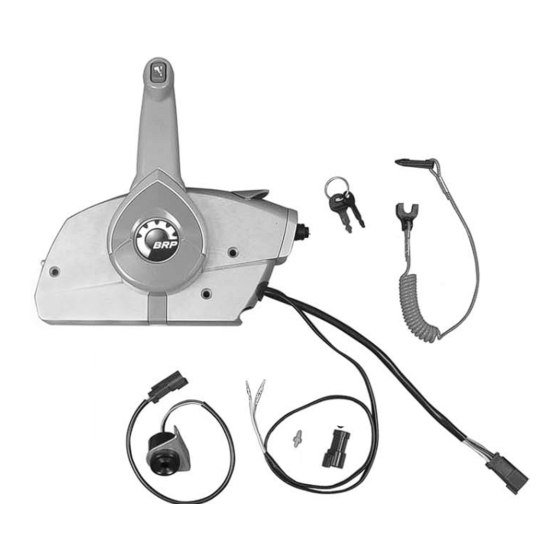
PREWIRED SURFACE MOUNT REMOTE CONTROL
APPLICATION
This surface mount remote control assembly is
designed for use on Evinrude
outboards.
SAFETY INFORMATION
For safety reasons, this kit should be installed by
an authorized Evinrude
instruction sheet is not a substitute for work experi-
ence. Additional helpful information may be found
in other service literature for your engine.
This instruction sheet uses the following signal
words identifying important safety messages.
DANGER
Indicates an imminently hazardous situa-
tion which, if not avoided, WILL result in
death or serious injury.
WARNING
Indicates a potentially hazardous situation
which, if not avoided, CAN result in severe
injury or death.
CAUTION
Indicates a potentially hazardous situation
which, if not avoided, MAY result in minor
or moderate personal injury or property
damage. It also may be used to alert
against unsafe practices.
IMPORTANT: Identifies information that will
help prevent damage to machinery and appears
next to information that controls correct assem-
bly and operation of the product.
These safety alert signal words mean:
ATTENTION!
BECOME ALERT!
YOUR SAFETY IS INVOLVED!
Printed in the Japan.
© 2005 BRP US Inc. All rights reserved.
TM, ® Trademarks and registered trademarks of Bombardier Recreational Products Inc. or its affiliates.
DSS04098I
®
and Johnson
®
®
/ Johnson
dealer. This
Always follow common shop safety practices. If
you have not had training related to common
shop safety practices, you should do so to pro-
®
tect yourself, as well as the people around you.
It is understood that this instruction sheet may be
translated into other languages. In the event of any
discrepancy, the English version shall prevail.
DO NOT do any repairs until you have read the in-
structions and checked the pictures relating to the
repairs.
Be careful, and never rush or guess a service pro-
cedure. Human error is caused by many factors:
carelessness, fatigue, overload, preoccupation,
unfamiliarity with the product, and drugs and alco-
hol use, to name a few. Damage to a boat and out-
board can be fixed in a short period of time, but
injury or death has a lasting effect.
When replacement parts are required, use
Evinrude/Johnson Genuine Parts or parts with
equivalent characteristics, including type, strength
and material. Using substandard parts could result
in injury or product malfunction.
Torque wrench tightening specifications must be
strictly followed. Replace any locking fastener
(locknut or patch screw) if its locking feature be-
comes weak. Definite resistance to turning must be
felt when reusing a locking fastener. If replacement
is specified or required because the locking fasten-
er has become weak, use only authorized
Evinrude/Johnson Genuine Parts.
If you use procedures or service tools that are not
recommended in this instruction sheet, YOU
ALONE must decide if your actions might injure
people or damage the outboard.
TO THE INSTALLER: Give this sheet to the owner.
Advise the owner of any special operation or main-
tenance information contained in the instructions.
TO THE OWNER: Save these instructions in your
owner's kit. This sheet contains information impor-
tant to the future use and maintenance of your out-
board.
1 of 24
Advertisement
Table of Contents

Related Manuals for BRP 5006181
Summary of Contents for BRP 5006181
-
Page 1: Installation Instructions
These safety alert signal words mean: ATTENTION! BECOME ALERT! YOUR SAFETY IS INVOLVED! Printed in the Japan. © 2005 BRP US Inc. All rights reserved. TM, ® Trademarks and registered trademarks of Bombardier Recreational Products Inc. or its affiliates. DSS04098I 1 of 24... - Page 2 CONTENTS OF KIT 004865 Name of Part 5006180 REMOTE CONTROL w/ TRIM SW 5006181 REMOTE CONTROL *REMOTE CONTROL AY 176360 *HORN 175974 *SWITCH, KEY & LANYARD 176288 **LANYARD Assy. 514696 *CONNECTOR, 3-Pin 514697 *LOCK WEDGE, 3-Pin connector 5006550 *MOUNTING BOLT & SPACER KIT...
-
Page 3: Remote Control Features
REMOTE CONTROL FEATURES 1. Trim and tilt switch 004849 2. Remote control lever 3. Fast idle lever 4. Emergency stop / key switch 5. Clip and lanyard assembly 6. Adjusting screw, remote control lever friction 7. Neutral lock lever 8. Shift position label 9. - Page 4 REMOTE CONTROL OPERATION Fast Idle Lever Use of the fast idle lever is not required on all Read and familiarize yourself with the complete models. Refer to operator’s guide for outboard. operation of the remote control before attempting to start the outboard. The fast idle lever can be used to open throttle without shifting into gear.
- Page 5 Control Handle Turn adjustment screw clockwise to increase the friction or counterclockwise to reduce the friction. IMPORTANT: Outboard must be OFF. If remote control cables are connected to outboard, turn propeller shaft while shifting remote control. With control handle in NEUTRAL and fast idle lever DOWN, lift the neutral lock lever, and move control handle to FORWARD gear or REVERSE gear position.
- Page 6 INSTALLATION INSTRUCTIONS Place remote control at proposed location and check clearance around remote control handle at Read and familiarize yourself with the complete full throttle in FORWARD and then at full throttle installation instructions of the remote control in REVERSE. There must be at least 4 in. (10 before attempting to install the remote control.
- Page 7 Determine Cable Length Remote Control Configuration Measure from center of control handle with The remote control lever can be positioned on remote control in mounting position, along either side of remote control, and the trim/tilt intended cable route to engine centerline at switch can be oriented to face the port or transom height as illustrated by dotted lines in starboard side of remote control.
- Page 8 Remote Control Configuration Diagrams IMPORTANT: Refer to the following diagrams for proper trim/tilt switch wire routing. Route the trim/ tilt wiring through the correct hole in control housing to allow proper movement of lever and to prevent trim/tilt switch wire damage. Starboard Mount w/Port Side Trim/Tilt Switch (Standard/Original Configuration) 1.
- Page 9 Starboard Mount w/Starboard Side Trim/Tilt Switch 1. Port side view of remote control 004883 2. Forward view of remote control 3. Shield Shield 004921 004918 004919 9 of 24...
- Page 10 Port Mount w/Starboard Side Trim/Tilt Switch 1. Starboard side view of remote control 004892 2. Forward view of remote control 3. Shield Shield 004922 004925 004269 10 of 24...
- Page 11 Port Mount w/Port Side Trim/Tilt Switch 1. Starboard side view of remote control 004893 2. Forward view of remote control 3. Shield 004927 Shield 004928 004929 11 of 24...
- Page 12 Control Lever Removal Remove the screw and washer. Detach remote control lever and joint from remote control. Place IMPORTANT: Refer to Trim/Tilt Switch Wire flat tip screwdriver in notch of joint to pry from Routing. Route trim/tilt wiring carefully when re- control.
- Page 13 Trim/Tilt Switch Wire Routing Refer Remote Control Configuration Diagrams. Note wire positions and routings. CAUTION To prevent trim tilt switch wiring from being damaged, route wires carefully and provide adequate slack in wiring. Refer to Remote Control Configuration Diagrams. 1. Cover, trim/tilt wire 004920 Remove control lever cover and note wire posi- tion and routing and position of wiring shield.
- Page 14 Position lever on remote control joint. Align Install Remote Control Cables splines of lever with splines of joint. Neutral lock Remove two screws and back cover from remote lever must align with neutral lock plate. Secure control housing. lever with screw and washer. Torque screw to 7 ft.
- Page 15 IMPORTANT: Use Evinrude/Johnson Genuine Align throttle cable trunnion and wiring grommet with back cover. Install back cover and screws. Parts or parts with equivalent characteristics, in- Apply Triple-Guard grease to assembly screws. cluding type, strength, and material. Torque screws to 36 in. lbs. (4 N·m). Install throttle cable and flat washer on to throttle pin and secure with new cotter pin.
- Page 16 Install Remote Control in Boat Electrical Connections Hold remote control(s) in selected position. Re- Install trim and tilt wiring into electrical connector. fer to specific outboard installation instruc- Position wiring terminals in connector housing as tions for information related to connecting indicated: remote controls to outboard.
- Page 17 REMOTE CONTROL OPERATION TEST NEUTRAL START TEST IMPORTANT: Disconnect all spark plug wires WARNING and/or disconnect crankshaft position sensor (CPS) connector to prevent outboard from start- Make certain starter will not operate when ing during test procedure. If remote control ca- the outboard is in gear.
- Page 18 OPERATOR TESTS AND ADJUSTMENTS EMERGENCY STOP SWITCH TEST IMPORTANT: Test operation of emergency WARNING stop switch at each outing. Refer to EMERGEN- CY STOP SWITCH TEST. If outboard does not Always use the safety lanyard when oper- stop, return control to dealer for repair. ating boat to help prevent a runaway boat and reduce the risk of personal injury or Check throttle friction.
- Page 19 MAINTENANCE Use Triple-Guard grease to lubricate all moving mechanisms and remote control cables. CAUTION Inspection and maintenance must be per- formed with outboard stopped. Disconnect emergency stop lanyard, disconnect bat- tery cables, and remove spark plug wires from spark plugs to prevent accidental starting of outboard.
- Page 20 20 of 24...
- Page 21 21 of 24...
- Page 22 22 of 24...
- Page 23 23 of 24...
- Page 24 M000149 50 24 of 24...