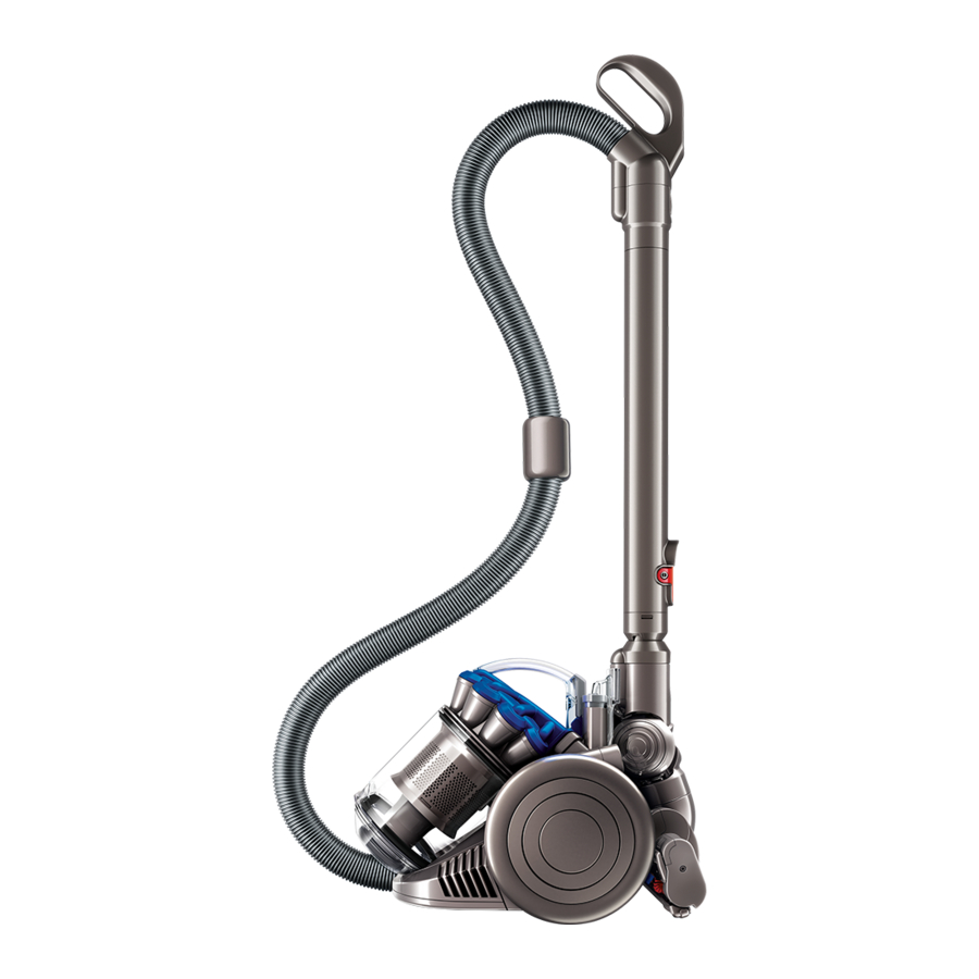
Dyson DC26 Service Manual
Hide thumbs
Also See for DC26:
- Operating manual (32 pages) ,
- Helpline manual (26 pages) ,
- Operating manual (32 pages)
Table of Contents
Advertisement
Advertisement
Table of Contents

Related Manuals for Dyson DC26


Summary of Contents for Dyson DC26
- Page 1 Service manual Issued September 09...
-
Page 2: Table Of Contents
Service manual This manual is written specifically for Dyson trained engineers and covers the full DC26 range. The service instructions assume the engineer has the approved tools and test equipment with them. Contents Page Features and benefits Electrical safety testing... -
Page 3: Features And Benefits
Features and benefits Root Cyclone™ technology Patented Dyson Technology that doesn’t lose suction power as you vacuum. dyson root cyclone technology Root cyclone Shroud Hygienic bin emptying No need to touch the dirt just push the button. Detachable handle Click fit tools directly to it for Concentration is not shrinking. -
Page 4: Electrical Safety Testing
Insulation test The following tests must be performed prior to These tests are vital to avoid any possibility and upon completion of all repairs to Dyson of personal injury to the end user. floorcare products and before any functional checks. -
Page 5: Wiring Schematic
Service manual Wiring schematic On/Off switch Motor bucket Cable rewind/ cable wiring assembly Contacts Cyclone inlet Resistance values TEST BETWEEN POINTS OHMS COMPONENT POWERCORD ASSY 1 Ω MAX POWERCORD ASSY 1 Ω MAX POWERCORD TO MAIN ON/OFF SWITCH 1 Ω MAX MAIN CHASSIS AND MOTOR ASSY (WITH CABLE REWIND ATTACHED) 6 Ω... -
Page 6: Electrical Fault Diagnosis
Service manual Electrical fault diagnosis No power to motor 1. Carry out a resistance test around the entire product (points 1-2) to determine there is a genuine fault. 2. If there is a fault check the plug, pins and entire length of the powercord for any signs of wear or damage. -
Page 7: General Notes
Ensure that protective gloves are worn where this symbol is shown. Some female terminal clips used in DC26 contain a locking mechanism. The release pip will need to be activated before separation from the male terminal can occur. - Page 8 Service manual 02 Undo the two fasteners in the post filter cover assembly. 03 Remove the cover. 04 Pull the hose retainer catch to release the hose from the base of the product.
- Page 9 Service manual 05 Firmly release the hose from the cyclone inlet. 06 Firmly pull the wheel and retainer off the cable rewind side of the product. 07 Undo the three screws in the cable rewind cover.
- Page 10 Service manual 08 Remove the cover. 09 Important: ensure the entire length of the cable is wound onto the cable rewind assembly. Prise the cable protector off the side of the chassis. 10 Important: press the cable rewind actuator and allow the cable rewind assembly to turn through two revolutions clockwise to remove any remaining tension...
- Page 11 Service manual 11 Undo the T-15 screw in the middle of the cable rewind spring assembly. 12 Carefully remove the spring assembly from the cable rewind assembly. 13 Remove the cable rewind assembly from the side of the product.
-
Page 12: Cable Rewind - Fitting
Service manual Cable rewind - fitting 14 Important: ensure the entire length of the cable is wound onto the cable rewind assembly before fitting onto the product. Failure to do so will result in the cable not adequately rewinding. 15 Lower the cable rewind assembly onto the spindle in the chassis. - Page 13 Service manual 17 Turn the drum of the cable rewind assembly by hand anti-clockwise through two revolutions. This will pre-set the spring with two turns. Failure to do this may result in a poorly performing cable rewind assembly. 18 Wind any slack cable back onto the drum of the cable rewind.
- Page 14 Service manual 20 Locate the cable rewind cover onto the side of the chassis. 21 Fit the three screws. Note: it is good practice to test the cable rewind for adequate actuation before continuing. If unsatisfactory, repeat steps 14-19. 22 Locate the wheel onto the side of the chassis.
- Page 15 Service manual 23 Firmly press the retainer into position ensuring each of the snaps locate. 24 Slide the hose into the cyclone inlet. Ensure it is pushed in as far as possible. Hose retainer Hook detail 25 Locate the hook detail into the front of the chassis.
- Page 16 Service manual 26 Fit the post filter assembly. 27 Fit the post filter cover assembly ensuring the tab details on the rear of the cover locate under the chassis. Tighten the two fasteners. 28 Locate the cyclone and bin assembly onto the product.
-
Page 17: Switch - Removal
Service manual Switch - removal 29 Remove the cyclone and bin assembly from the product. Remove the T-15 screw in the stow bracket. 30 Carefully release one side of the stow bracket away from the chassis to release it. Repeat on the other side. 31 Carefully slide a thin flat bladed screwdriver between the switch actuator and switch housing... - Page 18 Service manual 32 Repeat for the other actuator ensuring the screwdriver is inserted exactly where shown. Failure to insert it where shown may result in damage to the actuator housing. 33 Undo the two T-15 screws. 34 Firmly remove the actuator housing.
- Page 19 Service manual 35 Carefully release the switch and wires from the chassis. 36 Remove the glass cloth tape from the terminal boots. Put to one side for re-use. 37 Carefully detach the wires from the switch.
-
Page 20: Switch - Fitting
Service manual Switch - fitting 38 Attach the new switch to the wires. Wrap the previously removed length of glass cloth tape around the terminals ensuring they are fully covered. Note: if the glass cloth tape is unusable it will be necessary to cut a length approximately 60mm off a roll. - Page 21 Service manual 41 Fit each actuator ensuring the springs are positioned under the cruciform details. 42 Twist the stow bracket onto the chassis. Fit the T-15 screw.
-
Page 22: Brake Wheel Assy - Removal
Service manual Brake wheel assy - removal 43 Carefully remove the cable rewind actuator and spring, as previously shown (page 16, step 32). 44 Peel the end of the inlet seal from the chassis. Note: the inlet seal is spot glued in several places. - Page 23 Service manual 46 Prise the brake wheel housing and brake wheel assembly out of the chassis. 47 Separate the brake wheel assembly from the housing if necessary.
-
Page 24: Brake Wheel Assy - Fitting
Service manual Brake wheel assy - fitting Retaining ribs 48 If previously removed, fit the brake wheel assembly into the brake housing. Slide the housing into the chassis ensuring it locates over the retaining ribs. If fitted correctly, the housing will sit square within the chassis. - Page 25 Service manual 50 Apply several spots of glue around the edges of the inlet. Refit the inlet seal ensuring it is adequately seated in all channels . 51 Refit the cable rewind actuator. Note: it is good practice to test the cable rewind for adequate actuation.
-
Page 26: Cyclone Inlet, Chassis And Motor Assembly
Service manual Cyclone inlet, chassis and motor assembly replacement - dismantle Before continuing the following parts should be removed as previously shown: Cyclone and bin assembly, Wand and hose, Cable rewind assembly (pages 5-9) 52 Press the release catch and open the pre-filter door assembly. - Page 27 Service manual 55 Carefully prise the cyclone inlet out of the catch detail on the side of the chassis . 56 Carefully release the ESD wire and tab from the cyclone inlet. 57 If replacing any of the parts attached to the cyclone inlet, remove the screw in the underside of the inlet.
- Page 28 Service manual 58 Separate the cyclone inlet from the connector housing cap . 59 Twist the connector housing out of the connector housing cap .
- Page 29 Service manual Chassis and motor assembly 60 Please be aware that if the reason for the repair is due to a faulty motor or any components within the chassis, it will be necessary to replace the entire chassis and motor assembly as a whole. This is due to the complexity and time taken to remove and replace the motor from the chassis.
- Page 30 Service manual The following components are only offered separately and will require removing from the chassis and motor assembly, before fitting to the new assembly. 61 Remove the screw in the stow bracket. Carefully prise one side of the stow bracket away from the chassis to release it.
- Page 31 Service manual 64 Remove the Torx T-15 screw from the underside of the chassis. 65 Remove the exhaust grille.
-
Page 32: Replacement - Fitting
Service manual Cyclone inlet, chassis and motor assembly replacement - fitting 66 Locate the components that make up the bleed valve into the new chassis and motor assembly in the orientation shown. Fit the screws. 67 Locate the exhaust grille onto the side of the chassis. - Page 33 Service manual 69 Ensure the connector housing is securely located under the tab on the inlet assembly. 70 Locate the connector housing cap over the connector housing and cyclone inlet assembly. 71 Fit the Torx T-15 screw in the underside of the housing.
- Page 34 Service manual 72 Carefully locate the tab on the end of the ESD wire into the end of the connector housing cap. Dress the wire neatly within the channels provided. 73 Locate the end of the connector housing cap into the slot in the front of the chassis.
- Page 35 Service manual 75 Fit the screw in the side of the chassis. 76 Fit the screw in the underside of the product. 77 Twist the stow bracket onto the chassis. Fit the T-15 screw.
- Page 36 Service manual 78 Locate the pre-filter into the pre-filter door. Locate the pre-filter door onto the side of the chassis. After completing all the preceding steps the following parts should be fitted as previously shown: Cable rewind assembly (pages 10-14).
-
Page 37: Sub Assemblies - Bin Assembly
Service manual Sub assemblies - Bin assembly 79 The front bin catch can be removed from the bin assembly by gently prising off with a thin flat bladed screwdriver. 80 To fit, locate the spring onto the pip on the catch. Firmly press both parts onto the bin. - Page 38 Service manual 82 The bin base seal and FDC seal can be replaced by firmly pulling out of the bin base assembly. When fitting ensure all seals are adequately seated. 83 To locate the bin base assembly, locate one of the legs on the assembly onto the hinge point on the bin.
-
Page 39: Sub Assemblies - Wand Handle, Hose And Extension
Service manual Sub assemblies - wand handle, hose and extension tube assemblies 84 The swivel catch can be removed from the end of the handle, hose or extension tube by prising off with a thin flat bladed screwdriver. 85 To fit, locate the spring onto the rear of the swivel catch. - Page 40 Service manual Cable wiring assembly inspection The cable wiring retainer assembly is not offered as a separate customer service spare item. It can however be removed for diagnostic purposes (see page 4 for details). Remove the cable rewind assembly, ensuring all safety precautions are followed (see pages 5-9 for details).
- Page 41 Service manual 89 Carefully ease the lower edge of the cable wiring retainer assembly behind the bleed valve housing. 90 Lift the brake wheel assembly carefully upwards. Ease the top edge of the cable wiring retainer assembly behind the brake wheel. 91 Fit the four screws.
- Page 42 Service manual Main chassis and motor assembly Main chassis and motor assembly...
- Page 43 Service manual Main body parts Cable Rewind Assy Cable Rewind Spring Assy Screw Stow Bracket Screw Pre-filter Cable Rewind Cover Spring Screw Catch Screw Pre-filter Door Assy Screw Wheel Bleed Valve Housing Bleed Valve Housing Seal Bleed Valve Cap Assy Bleed Valve Spring Wheel...
- Page 44 Service manual Cyclone and bin assemblies Cyclone Assy Bin Seal Bin Catch Bin Assy Spring FDC Seal Bin Base Seal Bin Base Assy...
- Page 45 Service manual Handle, hose and floor tool Catch Wand Handle Assy Spring Extension Tube Assy Catch Spring Catch Dual Cavity Flat Out Head Spring Hose Assy Stair Tool Combination Tool Assy Instruction Pack Assy Tool Holster...