
Related Manuals for Samsung M171FN


Summary of Contents for Samsung M171FN
-
Page 1: Table Of Contents
MICROWAVE OVEN M171FN (WHITE) SERVICE Manual MICROWAVE OVEN CONTENTS 1. Precaution 2. Specifications 3. Operating Instructions 4. Disassembly and Reassembly 5. Alignment and Adjustments 6. Troubleshooting 7. Exploded Views and Parts List 8. Schematic Diagrams... -
Page 2: Exposure To Excessive Microwave Energy
PRECAUTIONS TO BE OBSERVED BEFORE AND DURING SERVICING TO AVOID POSSIBLE EXPOSURE TO EXCESSIVE MICROWAVE ENERGY (a) Do not operate or allow the oven to be (c) Before turning on microwave power operated with the door open. for any service test or inspection within (b) Make the following safety checks on the microwave generating all ovens to be serviced before activating... -
Page 3: Precaution
1. Precaution Follow these special safety precautions. Although the microwave oven is completely safe during ordinary use, repair work can be extremely hazardous due to possible exposure to microwave radiation, as well as potentially lethal high voltages and currents. 1-1 Safety precautions ( 11. - Page 4 1-2 Special Servicing Precautions (Continued) 17. When checking the continuity of the witches or transformer, always make sure that the power is OFF, and one of the lead wires is disconnected. 18. Components that are critical for safety are indicated in the circuit diagram by shading, or .
-
Page 5: Specifications
2. Specifications 2-1 Table of Specifications TIMER 35 MINUTES POWER SOURCE 230V 50Hz, SINGLE PHASE POWER CONSUMPTION 1,150W OUTPUT POWER 100W / 800W (ICE-705) OPERATING FREQUENCY 2,450MHz COOLING METHOD COOLING FAN MOTOR MAGNETRON OM75S(31)ESS OUTSIDE DIMENSIONS(mm) 489(W) x 275(H) x 397(D) OVEN DIMENSIONS(mm) 306(W) x 211(H) x 320(D) SHIPPING DIMENSIONS(mm) -
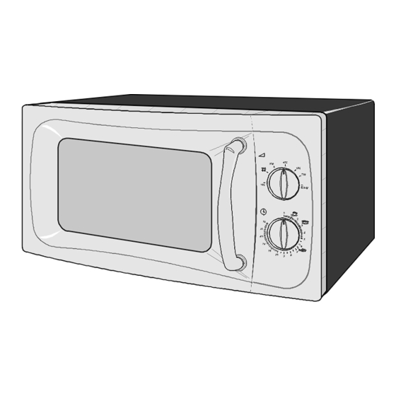
Page 6: Operating Instructions
3. Operating Instructions 3-1 Control Panel DEFROST VARIABLE COOKING POWER CONTROL KNOB INSTANT REHEAT TIMER KNOB 3-2 Features & External Views DOOR LATCHES VARIABLE COOKING VENTILATION HOLS LIGHT POWER CONTROL KNOB TIMER KNOB HANDLE ROLLER RING TURNTATBLE SAFETY DOOR COUPLER INTERLOCK HOLES 342mm 206mm... -
Page 7: Disassembly And Reassembly
4. Disassembly and Reassembly 4-1 Replacement of Magnetron, Motor Assembly and Lamp Remove the magnetron including the shield case, permanent magnet, choke coils and capacitors (all of which are contained in one assembly). 1. Disconnect all lead wires from the magnetron and lamp. 2. -
Page 8: Replacement Of Door Assembly
4-3 Replacement of Door Assembly 4-3-1 Removal of Door "C" Insert flat screwdriver into the gap between Door "A" and Door "C" to remove Door "C". Be careful when handling Door "C" because it is fragile. Then remove the door assembly. Door "A"... -
Page 9: Replacement Of Fuse
4-3-4 Reassembly Test After replacement of the defective component parts of the door, reassemble it and follow the instructions below for proper installation and adjustment so as to prevent an excessive microwave leakage. 1. When mounting the door to the oven, be sure to adjust the door parallel to the bottom line of the oven face plate by moving the upper hinge and lower hinge in the direction necessary for proper alignment. -
Page 10: Replacement Of Control Circuit Board
4-6 Replacement of Control Circuit Board 4-6-1 Removal of Control Box Assembly 1. Disconnect the connectors from the control box assembly. 2. Remove screws securing the control box assembly. 3. Remove the knobs of the control box A'ssy. 4. Remove the screw securing the timer. SCREW CONTROL-BOX - 8 -... -
Page 11: Alignment And Adjustments
5. Alignment and Adjustments PRECAUTION 1. High voltage is present at the high voltage terminals during any cook cycle. 2. It is neither necessary nor advisable to attempt measurement of the high voltage. 3. Before touching any oven components or wiring, always unplug the oven from its power source and discharge the high voltage capacitor. -
Page 12: High Voltage Capacitor
5-3 High Voltage Capacitor 1. Check continuity of the capacitor with the meter set at the highest resistance scale. Ω 2. Once the capacitor is charged, a normal capacitor shows continuity for a short time, and then indicates 9M 3. A shorted capacitor will show continuous continuity. Ω... -
Page 13: Output Power Of Magnetron
5-6 Output Power of Magnetron CAUTION MICROWAVE RADIATION PERSONNEL SHOULD NOT ALLOW EXPOSURE TO MICROWAVE RADIATION FROM MICROWAVE GENERATOR OR OTHER PARTS CONDUCTING MICROWAVE ENERGY. The output power of the magnetron can be measured by performing a water temperature rise test. Equipment needed : * Two 1-liter cylindrical borosilicate glass vessel (Outside diameter 190 mm) * One glass thermometer with mercury column... -
Page 14: Procedure For Measurement Of Microwave Energy Leakage
5-8 Procedure for Measurement of Microwave Energy Leakage 1) Pour 275±15cc of 20±5° C(68±9° F) water in a beaker which is graduated to 600cc, and place the beaker in the center of the oven. 2) Start to operate the oven and measure the leakage by using a microwave energy survey meter. -
Page 15: Troubleshooting
6. Troubleshooting WARNING FOR HIGH VOLTAGE 4000 VOLTS EXIST AT THE HIGH VOLTAGE AREA. DO NOT OPERATE THE OVEN WITH CABINET PARTS REMOVED. DO NOT REMOVE THE CABINET PARTS IF THE POWER SUPPLY CORD IS PLUGGED IN THE WALL OUTLET. UNPLUG THE POWER CORD BEFORE SERVICING. 6-1 Electrical Malfunction Parts Cause... - Page 16 6-1 Electrical Malfunction(continued) part Cause Diagnosis Remedy To increase the oven 1) Too small If a small amount of food is heated for a long time, water into water into a load period of microwave may turn off during operation. the oven.
-
Page 17: Unsatisfactory Cooking
6-2 Unsatisfactory Cooking Parts Cause Diagnosis Remedy 1) Open cathode of Check the terminals with a multimeter to see Replace magnetron. magnetron if the heater circuit is open. Check the H. V. Diode for continuity in the reverse and 2) Defective normal directions using meter. -
Page 18: Exploded Views And Parts List
7. Exploded Views and Parts List 7-1 Exploded Views D006 D005 D004 D003 M001 W002 D002 M029 M015 D015 D007 M019 M014 D011 D049 M017 M020 D019 M022 M023 C032 M051 M157 C024 B006 C005 M036 C092 M049 B001 B002 B018 M035 M048... -
Page 19: Main Parts List
7-2 Main Parts List Code No. Description Specification Q'ty Remark B001 3405-001034 SWITCH-MICRO 125/250VAC,16A,200GF,SPST-N B002 3405-001032 SWITCH-MICRO 125/250VAC,16A,200GF,SPDT B006 DE72-00137A LATCH-BODY NC2000(0.6/0.8/1.2),PP,-,-,-, B010 DE66-00093A LEVER-SWITCH(A) NC2000,PP-TH53,-,-,-,-,N B011 DE66-00094A LEVER-SWITCH(B) NC2000,PP-TH53,-,-,-,-,N B018 DE96-00120B ASSY BODY LATCH M1717N,NC2000(HANDLE) M001 DE70-00184P PANEL-OUTER MW850WA,C/STEEL,T0.5,-,-,-,P M014 3601-001126 FUSE-CARTRIDGE... - Page 20 7-3 Control & Door Parts List Code No. Description Specification Q'ty Remark C005 DE64-00906A CONTROL-PANEL M171FN/XEF,ABS,PURE-WHT,SE C024 DE45-10074H TIMER TMFK35MTM1,-,21V,-,50Hz,-,-,STL BK C032 3501-000309 RELAY-POWER 240V,3750VA,15000MA,-,6MS,20 C082 DE94-00883A ASSY CONTROL-BOX 230V50HZ,M171FN/XEF,PUR S.N.A C092 DE64-00649B KNOB-TIMER(D) M171FN/G271FN,ABS,PURE-WHT D002 DE64-00644B DOOR-A M171FN/G271FN,ABS,PURE-WHT(W9501) D003...
-
Page 21: Standard Parts List
7-4 Standard Parts List Code No. Description Specification Q'ty Remark DE60-10012A SCREW-TAP TITE -,SWR10,M4,L10,TH,+,-,3,ZPC2,- N/P EARTH DE60-10012A SCREW-TAP TITE -,SWR10,M4,L10,TH,+,-,3,ZPC2,- P/C EARTH DE60-10012A SCREW-TAP TITE -,SWR10,M4,L10,TH,+,-,3,ZPC2,- PCB EARTH DE60-10012A SCREW-TAP TITE -,SWR10,M4,L10,TH,+,-,3,ZPC2,- TCO-S/W DE60-10063A SCREW-TAP TH -,-,FEFN,-,TH,M4,-,L12,-,- O/PANEL DE60-10080B SCREW-WASHER -,2S,SWRCH18A,ZP2,PH,PI5,-,L10,-,- DE60-10080B SCREW-WASHER... -
Page 22: Schematic Diagrams
8. Schematic Diagrams 8-1 Schematic Diagrams (This Document can not be used without Samsung's authorization) MAGNETRON HIGH VOLTAGE DIODE TO CHASSIS HIGH VOLTAGE CAPACITOR H.V.FUSE SYMBOL COLOR BROWN BLACK BLUE ORANGE HIGH VOLTAGE TRANSFORMER - 2 0 -... - Page 23 ELECTRONICS This Service Manual is a property of Samsung Electronics Co.,Ltd. Any unauthorized use of Manual can be punished under applicable International and/or domestic law. © Samsung Electronics Co., Ltd. May 2003 Printed in Korea Code No. : DE68-03150A...