York YCAL0019 Installation Operation & Maintenance
Air-cooled scroll chillers
Hide thumbs
Also See for YCAL0019:
- Installation operation & maintenance (200 pages) ,
- Installation, operation and maintenance manual (230 pages)
Table of Contents
Advertisement
Advertisement
Table of Contents
Troubleshooting

Related Manuals for York YCAL0019


Summary of Contents for York YCAL0019
- Page 1 AIR-COOLED LIQUID CHILLERS HERMETIC SCROLL Supersedes 150.67-NM2 (1007) Form 150.67-NM2 (209) INSTALLATION, OPERATION, MAINTENANCE 035-21456-100 YCAL0019, 0022, 0028, 0033, 0043, 0046, 0052, 0056, 0066 AIR-COOLED SCROLL CHILLERS STYLE E (50 Hz) 15-65 TON LD10950 DUAL CIRCUIT SINGLE CIRCUIT R-410A...
- Page 2 All wir ing must be in ac cor dance with YORK’s pub lished spec i fi ca tions and must be per formed ONLY by qual i fi ed YORK personnel. YORK will not be re spon si ble for dam ag es/problems re sult ing from im prop er con nec tions to the con trols or ap pli ca tion of im prop er con trol sig nals.
- Page 3 While YORK makes no com mit ment to update or provide current information au to mat i cal ly to the manual owner, that information, if ap pli ca ble, can be ob tained by con tact ing the nearest YORK Engineered Systems Service offi...
-
Page 4: Table Of Contents
Condenser and Cabinet Options ......................17 Sound Reduction Options ........................17 UNIT COMPONENTS YCAL0019 - 0033 ....................19 CONTROL - POWER PANEL COMPONENTS YCAL0019-0033 ...............20 UNIT COMPONENTS - YCAL0043 – 0066 ....................21 CONTROL / POWER PANEL COMPONENTS - YCAL0043 – 0066 ............22 PRODUCT IDENTIFICATION NUMBER (PIN) ....................23 BASIC UNIT NOMENCLATURE .........................23... - Page 5 FORM 150.67-NM2 (209) TABLE OF CONTENTS (CONT’D) MOVING THE CHILLER ..........................29 Lifting Weights .............................29 UNIT RIGGING ............................31 SECTION 4 – INSTALLATION ...........................33 INSTALLATION CHECKLIST ........................33 HANDLING ..............................33 INSPECTION ...............................33 LOCATION AND CLEARANCES ........................33 Foundation ............................33 SPRING ISOLATORS (OPTIONAL) ......................34 COMPRESSOR MOUNTING ........................34 REMOTE COOLER OPTION ........................34 CHILLED LIQUID PIPING ...........................34 Ground Level Locations ........................34...
- Page 6 FORM 150.67-NM2 (209) TABLE OF CONTENTS (CONT’D) ELECTRICAL NOTES AND LEGEND ......................53 ELEMENTARY WIRING DIAGRAM ......................54 CONNECTION WIRING DIAGRAM ......................64 ELEMENTARY WIRING DIAGRAM DETAILS ....................68 DIMENSIONS (ENGLISH) ...........................70 TECHNICAL DATA – CLEARANCES .......................106 ISOLATORS ..............................107 Weight Distribution and Isolator Mounting PositionsYCAL0019 – 0033 (Without Pump Package Option) .....................107 Weight Distribution and Isolator Mounting PositionsYCAL0043 –...
- Page 7 FORM 150.67-NM2 (209) TABLE OF CONTENTS (CONT’D) SECTION 7 – UNIT CONTROLS ........................127 INTRODUCTION ............................127 IPU II and I/O Boards .........................127 Unit Switch ............................128 Display ..............................128 Keypad ..............................128 Battery Back-up ..........................128 Transformer ............................128 Single System Select and Programming # of Compressors ............128 “STATUS”...
- Page 8 RETURN CHILLED LIQUID CONTROL ....................159 RETURN CHILLLED LIQUID SYSTEM LEAD/LAG AND COMPRESSOR SEQUENCING ....160 ANTI-RECYCLE TIMER ..........................161 ANTI-COINCIDENCE TIMER ........................161 EVAPORATOR PUMP CONTROL & YORK HYDRO KIT PUMP CONTROL ..........161 EVAPORATOR HEATER CONTROL ......................161 PUMPDOWN CONTROL...........................161 STANDARD CONDENSER FAN CONTROL ....................161 YCAL0019 - 0028 LOW AMBIENT FAN CONTROL OPTION ..............165...
- Page 9 FORM 150.67-NM2 (209) TABLE OF CONTENTS (CONT’D) CHECKING INPUTS AND OUTPUTS .......................181 Digital Inputs ............................181 Analog Inputs – Temperature ......................181 Outside Air Sensor ..........................181 Liquid & Refrigerant Sensor Test Points ..................182 Analog Inputs – Pressure .........................183 Digital Outputs ...........................184 OPTIONAL PRINTER INSTALLATION .....................185 Parts ..............................185 The following parts are required: .....................185 Assembly and Wiring ........................185...
-
Page 10: Section 1 - General Chiller Information & Safety
Page 121). The unit is intended for cooling water or glycol • Only genuine YORK approved spare parts, oils, solutions and is not suitable for purposes other than coolants, and refrigerants must be used. those specifi ed in this manual. -
Page 11: Responsibility For Safety
This manual and any other document supplied with the unit are the property of YORK which reserves • Personal safety, safety of other personnel, and all rights. They may not be reproduced, in whole or the machinery. -
Page 12: Pressure Systems
General Chiller Introduction & Safety FORM 150.67-NM2 (209) Pressure Systems High Temperature and Pressure Cleaning The unit contains refrigerant vapor and liquid under High temperature and pressure cleaning methods pressure, release of which can be a danger and cause (e.g. steam cleaning) should not be used on any part injury. -
Page 13: Section 2 - Product Description
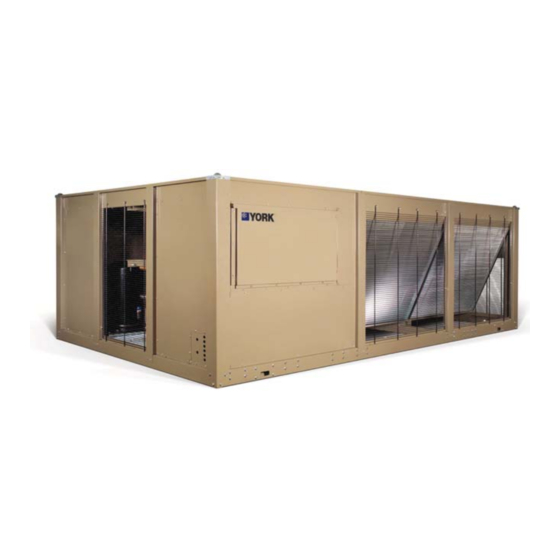
SECTION 2 – PRODUCT DESCRIPTION LD10950 DUAL CIRCUIT INTRODUCTION All exposed power wiring is routed through liquid- YORK Millennium ® Air-Cooled Scroll Chillers provide tight, non-metallic conduit. chilled water for all air con di tion ing ap pli ca tions using central station air han dling or terminal units. -
Page 14: Condenser
Product Description FORM 150.67-NM2 (209) The heat exchanger is a brazed plate stainless steel DISPLAY/PRINT of typical information: construction, single or dual circuit heat exchanger • Chilled liquid temperatures capable of refrigerant working pressure of 650 PSIG • Ambient temperature (3103 kPa) and liquid side pressure of 150 PSIG (1034 •... -
Page 15: Power Panel
FORM 150.67-NM2 (209) • Suction pressure cutout setting POWER PANEL • Each system suction pressure Each panel contains: • Discharge pressure (optional) • Compressor power terminals • Liquid Temperature Reset via a YORK ISN DDC • Compressor motor starting contactors per or Building Automation System (by others) via: l.E.C.** - a pulse width modulated (PWM) input as stan- • Control power terminals to accept incoming for dard. 115-1-60 control power - a 4-20 milliamp or 0 -10 VDC input with the • Fan contactors & overload current protection optional B.A.S. interface option. -
Page 16: Accessories And Options
BUILDING AUTOMATION SYSTEM INTER- SINGLE-POINT SUPPLY TERMINAL BLOCK FACE – The factory addition of a Printed Circuit Board – (standard on YCAL0019 – 0066 models) Includes to accept a 4-20 milliamp, 0-10VDC or contact closure enclosure, terminal-block and interconnecting wiring to input to reset the leaving chiller liquid temperature from the compressors. -
Page 17: Compressor, Piping, Evaporator Options
SPDT 5 amp 125/250VAC switch, Range 0 chilling below 30 °F (-1 °C) leaving brine temperature – 40 PSID, deadband 0.5 – 0.8 psi, with 1/4” NPTE for YCAL0019 – 0066 models. Option includes resized Pressure Connections. thermal expansion valve (Factory-Mounted). - Page 18 Product Description FORM 150.67-NM2 (209) COMPRESSOR ACOUSTIC SOUND BLANKET – Each compressor is individually enclosed by an acous- tic sound blanket. The sound blankets are made with one layer of acoustical absorbent textile fi ber of 5/8” (15mm) thickness; one layer of anti-vibrating heavy material thickness of 1/8”...
-
Page 19: Unit Components Ycal0019 - 0033
FORM 150.67-NM2 (209) UNIT COMPONENTS YCAL0019 - 0033 FAN ASSEMBLIES CONTROL / POWER PANEL CONDENSER COILS HEAT EXCHANGER COMPRESSORS FIG. 1 – UNIT COMPONENTS SINGLE SYSTEM UNITS JOHNSON CONTROLS... -
Page 20: Control - Power Panel Components Ycal0019-0033
Product Description FORM 150.67-NM2 (209) CONTROL - POWER PANEL COMPONENTS YCAL0019-0033 CIRCUIT BREAKER KEYPAD & DISPLAY UNIT SWITCH USER TERMINAL BLOCK COMPRESSOR CONTACTORS LD11463 FIG. 2 – CONTROL/POWER PANEL COMPONENTS SINGLE SYSTEM UNITS JOHNSON CONTROLS... -
Page 21: Unit Components - Ycal0043 - 0066
FORM 150.67-NM2 (209) UNIT COMPONENTS - YCAL0043 – 0066 FAN ASSEMBLIES CONDENSER COILS HEAT EXCHANGER LD12477 COMPRESSORS CONTROL / POWER PANEL FIG. 3 – UNIT COMPONENTS DUAL SYSTEM UNITS JOHNSON CONTROLS... -
Page 22: Control / Power Panel Components - Ycal0043 - 0066
Product Description FORM 150.67-NM2 (209) CONTROL / POWER PANEL COMPONENTS - YCAL0043 – 0066 TERMINAL BLOCK FAN FUSES CR1 / CR2 CTB1 COMPRESSOR CONTACTS LD11458a FIG. 4 – CONTROL/POWER PANEL COMPONENTS DUAL SYSTEM UNITS JOHNSON CONTROLS... -
Page 23: Product Identification Number (Pin)
BASE PRODUCT TyPE NOmINAL CAPACITy UNIT DESIgNATOR REFRIgERANT vOLTAgE/STARTER DESIgN/DEvELOPmENT LEvEL : Design Series E : R-410A : 380 / 3 / 50 : YORK : High Efficiency : Engineering : Chiller Change : Air-Cooled Even Number: or PIN Level : Condensing... - Page 24 Product Description FORM 150.67-NM2 (209) PRODUCT IDENTIFICATION NUMBER (PIN) (CON’T) FEATURE DESCRIPTION OPTION DESCRIPTION No Ambient Kits Required Low Ambient Kits Required Ambient Kits (PIN 20) High Ambient Kits Required High/Low Ambient Kits Required Special Ambient Kits Required No BAS Reset/Offset Required ISN Microgateway Required BAS Reset/Offset (PIN 21) BAS Reset/Offset Required...
- Page 25 FORM 150.67-NM2 (209) PRODUCT IDENTIFICATION NUMBER (PIN) (CON’T) FEATURE DESCRIPTION OPTION DESCRIPTION No Option Required GAUGE (PIN 34) Special Quote No Option Required OVERLOAD (PIN 35) Special Quote No Option Required PIN 36 (PIN 36) Special Quote Crankcase Heater Standard Crankcase Heater (PIN 37) Special Crankcase Heater Required 150 PSIG DWP Waterside...
- Page 26 Product Description FORM 150.67-NM2 (209) PRODUCT IDENTIFICATION NUMBER (PIN) (CON’T) FEATURE DESCRIPTION OPTION DESCRIPTION TEAO Fan Motors FANMOTORS Fan Motors (PIN 47) Special Fan Motors Required Wire Enclosures-Factory ENCL Enclosure Panel (PIN 48) Louvered Enclosure-Factory Special Enclosures Panels No Acoustic Blanket Required ACOUSTIC Acoustic Blanket (PIN 49) Acoustic Blanket Required...
- Page 27 FORM 150.67-NM2 (209) PRODUCT IDENTIFICATION NUMBER (PIN) (CON’T) FEATURE DESCRIPTION OPTION DESCRIPTION 18 months labor (year 1) – (entire unit), 30 months parts (year 1&2) (entire unit) 48 month parts (year2-5) (compressor only) 18 months labor (year 1) – (entire unit), 48 months parts (year 1&2) (entire unit) 48 month P&L (year2-5) (compressor only)
-
Page 28: Refrigerant Flow Diagram
Product Description FORM 150.67-NM2 (209) REFRIGERANT FLOW DIAGRAM AIR COOLED CONDENSERS HOT DISCHARGE GAS LINE OPTIONAL OPTIONAL DISCHARGE LINE BALL VALVE OPTIONAL SERVICE VALVE FIG. 5 – REFRIGERANT FLOW DIAGRAM LD11417 JOHNSON CONTROLS... -
Page 29: Section 3 - Handling And Storage
If any damage is evident, it should be noted on the carrier’s freight bill and a claim entered in accordance with the instructions given on the advice note. Major damage must be reported immediately to your local YORK representative. JOHNSON CONTROLS... - Page 30 Handling and Storage FORM 150.67-NM2 (209) MOVING THE CHILLER (YCAL0019 – 0033 SINGLE CIRCUIT ONLY) Prior to moving the unit, ensure that the installation site is suitable for installing the unit and is easily capable of supporting the weight of the unit and all associated services.
-
Page 31: Unit Rigging
Forks must extend beyond the width of the unit for proper lift. The thick- ness of the fork blade must be smaller then the opening of the lifting hole. Improper fork positioning could result in damage to the unit. FIG. 6 – UNIT RIGGING/LIFTING (YCAL0019 – 0033 SINGLE CIRCUIT MODELS ONLY) JOHNSON CONTROLS... - Page 32 Handling and Storage FORM 150.67-NM2 (209) FIG. 6A – UNIT RIGGING/LIFTING (YCAL0043- 0066 DUAL CIRCUIT MODELS) Use spreader bars to avoid lifting chains hitting the LD10951 chiller. Never lift the chiller using a forklift or by hooking to the top rails. Use only the lifting holes provided.
-
Page 33: Section 4 - Installation
INSPECTION equipment must be commissioned Immediately upon receiving the unit, it should be and serviced by an authorized YORK inspected for possible damage which may have occurred during transit. If damage is evident, it should service mechanic or a qualifi ed service be noted in the carrier’s freight bill. -
Page 34: Spring Isolators (Optional)
Hand stop valves should be installed in all lines to fa- Considerations should be made utilizing noise levels cilitate servicing. published in the YORK Engineering Guide for the specific chiller model. Sound blankets for the Piping to the inlet and outlet connections of the chiller should include high-pressure rubber hose or piping compressors and low sound fans are available. -
Page 35: Pipework Arrangement
STRAINER formation of condensation on lines in warm humid locations. 7. A chilled water fl ow switch, (either by YORK or PRESSURE TAPPING others) MUST be installed in the leaving water piping of the cooler. There should be a straight horizontal run of at least 5 diameters on each side of the switch. -
Page 36: Duct Work Connection
Installation FORM 150.67-NM2 (209) Copper power wiring only should be used for supplying DUCT WORK CONNECTION power to the chiller. This is recommended to avoid safety General Requirements and reliability issues resulting from connection failure at The following duct work recommendations are the power connections to the chiller. -
Page 37: Alarm Status Contacts
FORM 150.67-NM2 (209) Alarm Status Contacts Load Limit Input Normally-open contacts are available for each re frigerant Load limiting is a feature that prevents the unit from system. These normally-open contacts close when the loading beyond a desired value. The unit can be “load system is functioning normally. -
Page 38: Single-Point Supply Connection
Installation FORM 150.67-NM2 (209) SINGLE-POINT SUPPLY CONNECTION – TERMINAL BLOCK, NON-FUSED DISCONNECT SWITCH OR CIRCUIT BREAKER Power Panel Power Panel Power Panel Control Panel Control Panel Control Panel Terminal Block, Terminal Block, MICROPANEL MICROPANEL NF Disconnect SW NF Disconnect SW or Circuit Breaker or Circuit Breaker CTB2... -
Page 39: Control Wiring
FORM 150.67-NM2 (209) CONTROL WIRING FLOW SW REMOTE START/STOP LOAD LIMIT INPUT CTB1 LD07725A * Factory wired with optional transformer. CTB2 LD07730 It is possible that multiple sources of power can be supplying the unit power panel. To prevent serious injury or death, the technician should verify that NO LETHAL VOLTAGES are present inside the panel AFTER disconnecting power, PRIOR to working on equipment. -
Page 40: Section 5 - Technical Data
Technical Data FORM 150.67-NM2 (209) SECTION 5 – TECHNICAL DATA OPERATIONAL LIMITATIONS (ENGLISH) TABLE 1 – TEMPERATURES AND FLOWS ENGLISH LEAVING WATER COOLER FLOW (GPM) AIR ON CONDENSER ( °F) TEMPERATURE ( °F) YCAL 0019 0022 0028 0033 0043 0046 0052 0056 0066... - Page 41 FORM 150.67-NM2 (209) YCAL0019-0033 HEAT EXCHANGER FLOW, GPM ENGLISH 1000.0 100.0 10.0 1000 FLOW, GPM LD14085 YCAL COOLER CURVE 0019 0022 0028 0033 Note: Water Pressure Drop Curves may extend past the minimum and maximum water fl ow ranges. JOHNSON CONTROLS...
- Page 42 Technical Data FORM 150.67-NM2 (209) YCAL0043-0066 HEAT EXCHANGER FLOW, GPM ENGLISH 1000 FLOW, GPM LD12451 YCAL COOLER CURVE 0043 0046 0052 0056 0066 Note: Water Pressure Drop Curves may extend past the minimum and maximum water fl ow ranges. JOHNSON CONTROLS...
-
Page 43: Operational Limitations (Si)
1. For leaving brine temperature below 40 °F (4.4 °C), contact your nearest YORK Offi ce for application requirements. 2. For leaving water temperature higher than 55 °F (12.8 °C), contact the nearest YORK Offi ce for application guidelines. 3. The evaporator is protected against freezing to -20 °F (-28.8 °C) with an electric heater as standard. - Page 44 Technical Data FORM 150.67-NM2 (209) OPERATIONAL LIMITATIONS (SI) YCAL0019-0033 HEAT EXCHANGER FLOW, GPM 1000.0 100.0 10.0 LD14086 FLOW, L/S YCAL COOLER CURVE 0019 0022 0028 0033 Note: Water Pressure Drop Curves may extend past the minimum and maximum water fl ow ranges.
- Page 45 FORM 150.67-NM2 (209) OPERATIONAL LIMITATIONS (SI) YCAL0043-0066 HEAT EXCHANGER FLOW, GPM 1000 FLOW, L/S LD12452 YCAL COOLER CURVE 0043 0046 0052 0056 0066 Note: Water Pressure Drop Curves may extend past the minimum and maximum water fl ow ranges. JOHNSON CONTROLS...
-
Page 46: Physical Data (English)
Technical Data FORM 150.67-NM2 (209) PHYSICAL DATA (ENGLISH) YCAL0019_ – YCAL0066_ 50Hz TABLE 4 – PHYSICAL DATA (ENGLISH) Dimension General Unit Data Nominal Comp. Capacity Shipping Weight Operating Weight Circuit 1 Circuit 2 Refrigerant Model Number of Charge, Oil Charge, Alum. - Page 47 FORM 150.67-NM2 (209) PHYSICAL DATA (ENGLISH) (CON’T) YCAL0019_ – YCAL0066_ Condenser Condenser Fans, Low Sound Condenser Fans, Ultra Quiet Evaporator Maxi- Maxi- Nom. Min. Max. Water Model Number of Total Refrig- Number of Fans Fan Number of Fans Fan Fins Total Total Water...
-
Page 48: Sound Data (English)
YCAL0019_ – YCAL0033_ TABLE 5 – SOUND DATA – 50 HZ SINGLE CIRCUIT UNITS 50Hz Line Frequency Low Noise Fan (Standard) 1000 2000 4000 8000 YCAL0019 YCAL0022 YCAL0028 YCAL0033 50Hz Line Frequency Low Noise Fan with compressor sound blankets 1000 2000 4000... - Page 49 FORM 150.67-NM2 (209) SOUND DATA (ENGLISH) YCAL0043_ – YCAL0066_ TABLE 5 – SOUND DATA – 50 Hz – (Cont’d) DUAL CIRCUIT UNITS 50Hz Line Frequency Low Noise Fan (Standard) R-410A 1000 2000 4000 8000 YCAL0043 YCAL0046 YCAL0052 YCAL0056 YCAL0066 50Hz Line Frequency Low Noise Fan with compressor sound blankets installed R-410A 1000 2000...
-
Page 50: Electrical Data (English)
Technical Data FORM 150.67-NM2 (209) eleCTRICal DaTa (eNGlISH) YCal0019_ – YCal0066_ (Without Pump) SINGLE POINT FIELD SUPPLIED POWER WIRING (See Fig. 8) (One Field Provided Power Supply to the chiller. Field connections to Factory Provided Power Terminal Block (standard), Non-Fused Disconnect Switch (optional) or Circuit Breaker (optional)). - Page 51 FORM 150.67-NM2 (209) ELECTRICAL DATA (ENGLISH) (CON’T) YCAL0019_ – YCAL0066_ SINGLE POINT FIELD SUPPLIED POWER WIRING (See Fig. 8) (One Field Provided Power Supply to the chiller. Field connections to Factory Provided Power Terminal Block (standard), Non-Fused Disconnect Switch (optional) or Circuit Breaker (optional)). SYSTEM #1 COMPRESSOR &...
-
Page 52: Electrical Data
Technical Data FORM 150.67-NM2 (209) ELECTRICAL DATA TABLE 7 – MICRO PANEL POWER SUPPLY OVER CURRENT PROTECTION, CONTROL UNIT VOLTAGE SEE NOTE B NF DISC Sw POWER NOTE A UNIT MODELS w/o VOLTAGE CONTROL 115-1-60/50 30 A / 240V TRANS 380/415-1-60 30A / 415V A. -
Page 53: Electrical Notes And Legend
FORM 150.67-NM2 (209) ELECTRICAL NOTES AND LEGEND NOTES: 1. Minimum Circuit Ampacity (MCA) is based on 125% of the rated load amps for the larg est motor plus 100% of the rated load amps for all other loads included in the cir cuit, per N.E.C. Article 430-24. If the optional Factory Mount ed Control Transformer is provided, add the following MCA values to the electrical tables for the system providing power to the transformer: -17, add 2.5 amps;... -
Page 54: Elementary Wiring Diagram
Technical Data FORM 150.67-NM2 (209) ELEMENTARY WIRING DIAGRAM YCAL0019, 0022, 0028 & 0033 STANDARD UNITS YCAL0019, 0022 0028 & 0033 STANDARD LOW SOUND UNITS YCAL0028 & 0033 ULTRA LOW SOUND UNITS FIG. 10 – CONTROL CIRCUIT, SINGLE JOHNSON CONTROLS... - Page 55 FORM 150.67-NM2 (209) ELEMENTARY WIRING DIAGRAM (CON’T) LD12699D JOHNSON CONTROLS...
- Page 56 Technical Data ELEMENTARY WIRING DIAGRAM FORM 150.67-NM2 (209) YCAL0043, 0046, 0052 & 0066 STANDARD UNITS YCAL0043, 0046, 0052 & 0066 STANDARD LOW SOUND UNITS YCAL0043, 0046, 0052 & 0066 ULTRA LOW SOUND UNITS FIG. 11 – CONTROL CIRCUIT, DUAL JOHNSON CONTROLS...
- Page 57 FORM 150.67-NM2 (209) ELEMENTARY WIRING DIAGRAM (CON’T) LD12693C JOHNSON CONTROLS...
- Page 58 Technical Data FORM 150.67-NM2 (209) ELEMENTARY WIRING DIAGRAM YCAL 0019 & 0022 STANDARD UNITS YCAL 0019 & 0022 STANDARD LOW SOUND UNITS LD 12197 FIG. 12 – POWER CIRCUIT, SINGLE JOHNSON CONTROLS...
- Page 59 FORM 150.67-NM2 (209) ELEMENTARY WIRING DIAGRAM (CON’T) LD 12198 JOHNSON CONTROLS...
- Page 60 Technical Data FORM 150.67-NM2 (209) ELEMENTARY WIRING DIAGRAM YCAL 0019, 0022, 0028 & 0033 STANDARD UNITS YCAL 0019, 0022, 0028 & 0033 STANDARD LOW SOUND UNITS YCAL 0028 & 0033 ULTRA LOW SOUND UNITS LD12701 FIG. 13 – POWER CIRCUIT, SINGLE, STYLE D JOHNSON CONTROLS...
- Page 61 FORM 150.67-NM2 (209) ELEMENTARY WIRING DIAGRAM (CON’T) LD12702 JOHNSON CONTROLS...
- Page 62 Technical Data FORM 150.67-NM2 (209) ELEMENTARY WIRING DIAGRAM YCAL0043, 0046, 0052, 0056 & 0066 STANDARD UNITS YCAL0043, 0046, 0052, 0056 & 0066STANDARD LOW SOUND UNITS YCAL0043, 0046, 0052, 0056 & 0066 ULTRA LOW SOUND UNITS FIG. 13A – POWER CIRCUIT, DUAL, STYLE D LD12695 JOHNSON CONTROLS...
- Page 63 FORM 150.67-NM2 (209) ELEMENTARY WIRING DIAGRAM (CON’T) LD12696 JOHNSON CONTROLS...
-
Page 64: Connection Wiring Diagram
FORM 150.67-NM2 (209) CONNECTION WIRING DIAGRAM YCAL0019, 0022, 0028, & 0033 STANDARD UNITS YCAL0019, 0022, 0028, & 0033 STANDARD LOW SOUND UNITS YCAL 0028 & 0033 ULTRA LOW SOUND UNITS FIG. 14 – CONNECTION WIRING DIAGRAM MICROBOARD, SINGLE CIRCUIT JOHNSON CONTROLS... - Page 65 FORM 150.67-NM2 (209) CONNECTION WIRING DIAGRAM (CON’T) LD12703B JOHNSON CONTROLS...
- Page 66 Technical Data FORM 150.67-NM2 (209) CONNECTION WIRING DIAGRAM YCAL0043, 0046, 0052, 0056 & 0066 STANDARD UNITS YCAL0043, 0046, 0052, 0056 & 0066 STANDARD LOW SOUND UNITS YCAL0043, 0046, 0052, 0056 & 0066 ULTRA LOW SOUND UNITS FIG. 14A – CONNECTION WIRING DIAGRAM MICROBOARD, DUAL CIRCUIT JOHNSON CONTROLS...
- Page 67 FORM 150.67-NM2 (209) CONNECTION WIRING DIAGRAM (CON’T) LD12697B JOHNSON CONTROLS...
-
Page 68: Elementary Wiring Diagram Details
FORM 150.67-NM2 (209) ELEMENTARY WIRING DIAGRAM DETAILS YCAL0019, 0022, 028 & 0033 STANDARD UNITS YCAL0019, 0022, 028 & 0033 STANDARD LOW SOUND UNITS YCAL0028 & 0033 ULTRA LOW SOUND UNITS LD12690C FIG. 15 – ELEMENTARY WIRING DIAGRAM DETAILS, SINGLE CIRCUIT... - Page 69 FORM 150.67-NM2 (209) ELEMENTARY WIRING DIAGRAM DETAILS YCAL0043, 0046, 0052, 0056 & 0066 STANDARD UNITS YCAL0043, 0046, 0052, 0056 & 0066 STANDARD LOW SOUND UNITS YCAL0043, 0046, 0052, 0056 & 0066 ULTRA LOW SOUND UNITS LD12689 FIG. 16 – ELEMENTARY WIRING DIAGRAM DETAILS, DUAL CIRCUIT JOHNSON CONTROLS...
-
Page 70: Dimensions (English)
Site restrictions may compromise minimum clearances indicated below, resulting in un pre dict able airfl ow patterns and possible diminished performance. YORK’s unit controls will optimize operation without nuisance high-pres sure safety cutouts; however, the system designer must consider potential performance degradation. Recommended minimum clearances: front to wall –... - Page 71 FORM 150.67-NM2 (209) DIMENSIONS – YCAL0019 (ENGLISH) (CON’T) 9/16" DIA MOUNTING HOLES(typ) 1 1/16" CONTROL COMPR PANEL 44 3/8" END CAP WIDTH 32 1/8" 6 1/8" 1 1/16" ORIGIN 2 1/4" 5" TOP VIEW 17" 1" 9 1/16" CONTROL PANEL 38 3/16"...
- Page 72 Site restrictions may compromise minimum clearances indicated below, resulting in un pre dict able airfl ow patterns and possible diminished performance. YORK’s unit controls will optimize operation without nuisance high-pres sure safety cutouts; however, the system designer must consider potential performance degradation. Recommended minimum clearances: front to wall –...
- Page 73 FORM 150.67-NM2 (209) DIMENSIONS – YCAL0022 (ENGLISH) (CON’T) 9/16" DIA MOUNTING HOLES(typ) 1 1/16" CONTROL COMPR PANEL 44 3/8" END CAP WIDTH 32 1/8" 6 1/8" 1 1/16" ORIGIN 2 1/4" 5" TOP VIEW 17" 1" 9 1/16" CONTROL PANEL 38 3/16"...
- Page 74 Site restrictions may compromise minimum clearances indicated below, resulting in un pre dict able airfl ow patterns and possible diminished performance. YORK’s unit controls will optimize operation without nuisance high-pres sure safety cutouts; however, the system designer must consider potential performance degradation. Recommended minimum clearances: front to wall –...
- Page 75 FORM 150.67-NM2 (209) DIMENSIONS – YCAL0028 (ENGLISH) (CON’T) 5/8" DIA MOUNTING HOLES(TYP) 1 1/16" CONTROL COMPR PANEL 44 3/8" END CAP WIDTH 32 1/8" 6 1/8" 1 1/16" 1 7/8" ORIGIN 5" 17" TOP VIEW R-410A CHILLER 1" 9" CONTROL PANEL 42 1/8"...
- Page 76 Site restrictions may compromise minimum clearances indicated below, resulting in un pre dict able airfl ow patterns and possible diminished performance. YORK’s unit controls will optimize operation without nuisance high-pres sure safety cutouts; however, the system designer must consider potential performance degradation. Recommended minimum clearances: front to wall –...
- Page 77 FORM 150.67-NM2 (209) DIMENSIONS – YCAL0033 (ENGLISH) (CON’T) 9/16" DIA MOUNTING HOLES(typ) 1 1/16" CONTROL COMPR PANEL 44 3/8" END CAP WIDTH 32 1/8" 6 1/8" 1 1/16" 1 7/8" ORIGIN 5" 17" TOP VIEW 1" 9" CONTROL PANEL 42 1/8" 3 3/8"...
- Page 78 Site restrictions may compromise minimum clearances indicated below, resulting in un pre dict able airfl ow patterns and possible diminished performance. YORK’s unit controls will optimize operation without nuisance high-pres sure safety cutouts; however, the system designer must consider potential performance degradation. Recommended minimum clearances: front to wall –...
- Page 79 FORM 150.67-NM2 (209) DIMENSIONS – YCAL0043 (ENGLISH) (CON’T) 9/16" DIA MOUNTING HOLES(typ) 1 1/16" COIL COOLER 90 9/16" END CAP WIDTH 45 5/16" 1 1/1 9 13/16" 9 13/ ORIGIN 21 13/16" TOP VIEW 5 5/16" 38" CONTROL PANEL 25 3/8" 13 5/8"...
- Page 80 Site restrictions may compromise minimum clearances indicated below, resulting in un pre dict able airfl ow patterns and possible diminished performance. YORK’s unit controls will optimize operation without nuisance high-pres sure safety cutouts; however, the system designer must consider potential performance degradation. Recommended minimum clearances: front to wall –...
- Page 81 FORM 150.67-NM2 (209) DIMENSIONS – YCAL0046 (ENGLISH) (CON’T) 9/16" DIA MOUNTING HOLES(typ) 1 1/16" COIL COOLER 90 9/16" END CAP WIDTH 45 5/16" 1 1/16" 9 13/16" 9 13/16 ORIGIN TOP VIEW 20 1/16" 5 5/16" 38" CONTROL PANEL 25 3/8" 13 5/8"...
- Page 82 Site restrictions may compromise minimum clearances indicated below, resulting in un pre dict able airfl ow patterns and possible diminished performance. YORK’s unit controls will optimize operation without nuisance high-pres sure safety cutouts; however, the system designer must consider potential performance degradation. Recommended minimum clearances: front to wall –...
- Page 83 FORM 150.67-NM2 (209) DIMENSIONS – YCAL0052 (ENGLISH) (CON’T) 5/8" DIA MOUNTING HOLES(TYP) 1 1/16" COIL COOLER 90 9/16" END CAP WIDTH 45 5/16" 1 1/16" 9 13/16" 9 13/16" ORIGIN TOP VIEW 20 1/16" R-410A CHILLER 5 5/16" 38" CONTROL PANEL 25 3/8"...
- Page 84 Site restrictions may compromise minimum clearances indicated below, resulting in un pre dict able airfl ow patterns and possible diminished performance. YORK’s unit controls will optimize operation without nuisance high-pres sure safety cutouts; however, the system designer must consider potential performance degradation. Recommended minimum clearances: front to wall –...
- Page 85 FORM 150.67-NM2 (209) DIMENSIONS – YCAL0056 (ENGLISH) (CON’T) 5/8" DIA MOUNTING HOLES(TYP) 1 1/16" COIL COOLER 90 9/16" END CAP WIDTH 45 5/16" 1 1/16" 1,015 ORIGIN 9 13/16" 9 13/16" TOP VIEW 18 7/16" R-410A CHILLER 5 3/16" 38" CONTROL PANEL 25 3/8"...
- Page 86 Site restrictions may compromise minimum clearances indicated below, resulting in un pre dict able airfl ow patterns and possible diminished performance. YORK’s unit controls will optimize operation without nuisance high-pres sure safety cutouts; however, the system designer must consider potential performance degradation. Recommended minimum clearances: front to wall –...
- Page 87 FORM 150.67-NM2 (209) DIMENSIONS – YCAL0066 (ENGLISH) (CON’T) 9/16" DIA MOUNTING HOLES(typ) 1 1/16" COIL COOLER 90 9/16" END CAP WIDTH 43 5/16" 1 1/16" ORIGIN 9 13/16" 9 13/16 16 11/16" TOP VIEW C C G 5 3/16" 38" CONTROL PANEL 25 3/8"...
- Page 88 Site restrictions may compromise minimum clearances indicated below, resulting in un pre dict able airfl ow patterns and possible diminished performance. YORK’s unit controls will optimize operation without nuisance high-pres sure safety cutouts; however, the system designer must consider potential performance degradation. Recommended minimum clearances: front to wall – 2m;...
- Page 89 FORM 150.67-NM2 (209) DIMENSIONS – YCAL0019 (SI) (CON’T) 14 DIA MOUNTING HOLES(typ) CONTROL COMPR PANEL 1128 END CAP WIDTH ORIGIN TOP VIEW CONTROL PANEL (2) 178 X 57 FORKLIFT HOLES BOTH SIDES (2) 76 X 38 RIGGING HOLES BOTH SIDES...
- Page 90 Site restrictions may compromise minimum clearances indicated below, resulting in un pre dict able airfl ow patterns and possible diminished performance. YORK’s unit controls will optimize operation without nuisance high-pres sure safety cutouts; however, the system designer must consider potential performance degradation. Recommended minimum clearances: front to wall – 2m;...
- Page 91 FORM 150.67-NM2 (209) DIMENSIONS – YCAL0022 (SI) (CON’T) 14 DIA MOUNTING HOLES(typ) CONTROL COMPR PANEL 1128 END CAP WIDTH ORIGIN TOP VIEW CONTROL PANEL (2) 178 X 57 FORKLIFT HOLES BOTH SIDES (2) 76 X 38 RIGGING HOLES BOTH SIDES 1130 1892 2466...
- Page 92 Site restrictions may compromise minimum clearances indicated below, resulting in un pre dict able airfl ow patterns and possible diminished performance. YORK’s unit controls will optimize operation without nuisance high-pres sure safety cutouts; however, the system designer must consider potential performance degradation. Recommended minimum clearances: front to wall – 2m;...
- Page 93 FORM 150.67-NM2 (209) DIMENSIONS – YCAL0028 (SI) (CON’T) 16 DIA MOUNTING HOLES(TYP) CONTROL COMPR PANEL 1128 END CAP WIDTH ORIGIN TOP VIEW R-410A CHILLER CONTROL PANEL 1070 (2) 178 X 57 FORKLIFT HOLES (2) 76 X 38 BOTH SIDES RIGGING HOLES 1282 BOTH SIDES 2044...
- Page 94 Site restrictions may compromise minimum clearances indicated below, resulting in un pre dict able airfl ow patterns and possible diminished performance. YORK’s unit controls will optimize operation without nuisance high-pres sure safety cutouts; however, the system designer must consider potential performance degradation. Recommended minimum clearances: front to wall – 2m;...
- Page 95 FORM 150.67-NM2 (209) DIMENSIONS – YCAL0033 (SI) (CON’T) 14 DIA MOUNTING HOLES(typ) CONTROL COMPR PANEL 1128 END CAP WIDTH ORIGIN TOP VIEW CONTROL PANEL 1070 (2) 178 X 57 FORKLIFT HOLES BOTH SIDES (2) 76 X 38 RIGGING HOLES 1282 BOTH SIDES 2044 2669...
- Page 96 Site restrictions may compromise minimum clearances indicated below, resulting in un pre dict able airfl ow patterns and possible diminished performance. YORK’s unit controls will optimize operation without nuisance high-pres sure safety cutouts; however, the system designer must consider potential performance degradation. Recommended minimum clearances: front to wall – 2m;...
- Page 97 FORM 150.67-NM2 (209) DIMENSIONS – YCAL0043 (SI) (CON’T) 14 DIA MOUNTING HOLES(typ) COIL COOLER 2301 END CAP WIDTH 1150 ORIGIN TOP VIEW CONTROL PANEL TWO LIFTING HOLES BOTH SIDES 3678 FRONT VIEW JOHNSON CONTROLS...
- Page 98 Site restrictions may compromise minimum clearances indicated below, resulting in un pre dict able airfl ow patterns and possible diminished performance. YORK’s unit controls will optimize operation without nuisance high-pres sure safety cutouts; however, the system designer must consider potential performance degradation. Recommended minimum clearances: front to wall – 2m;...
- Page 99 FORM 150.67-NM2 (209) DIMENSIONS – YCAL0046 (SI) (CON’T) 14 DIA MOUNTING HOLES(typ) COIL COOLER 2301 END CAP WIDTH 1150 ORIGIN TOP VIEW CONTROL PANEL TWO LIFTING HOLES BOTH SIDES 3678 FRONT VIEW JOHNSON CONTROLS...
- Page 100 Site restrictions may compromise minimum clearances indicated below, resulting in un pre dict able airfl ow patterns and possible diminished performance. YORK’s unit controls will optimize operation without nuisance high-pres sure safety cutouts; however, the system designer must consider potential performance degradation. Recommended minimum clearances: front to wall – 2m;...
- Page 101 FORM 150.67-NM2 (209) DIMENSIONS – YCAL0052 (SI) (CON’T) 16 DIA MOUNTING HOLES(TYP) COIL COOLER 2301 END CAP WIDTH 1150 ORIGIN TOP VIEW R-410A CHILLER CONTROL PANEL TWO LIFTING HOLES BOTH SIDES 3678 FRONT VIEW JOHNSON CONTROLS...
- Page 102 Site restrictions may compromise minimum clearances indicated below, resulting in un pre dict able airfl ow patterns and possible diminished performance. YORK’s unit controls will optimize operation without nuisance high-pres sure safety cutouts; however, the system designer must consider potential performance degradation. Recommended minimum clearances: front to wall – 2m;...
- Page 103 FORM 150.67-NM2 (209) DIMENSIONS – YCAL0056 (SI) (CON’T) 16 DIA MOUNTING HOLES(TYP) COIL COOLER 2301 END CAP WIDTH 1151 1,015 ORIGIN TOP VIEW R-410A CHILLER CONTROL PANEL TWO LIFTING HOLES BOTH SIDES 3678 FRONT VIEW JOHNSON CONTROLS...
- Page 104 Site restrictions may compromise minimum clearances indicated below, resulting in un pre dict able airfl ow patterns and possible diminished performance. YORK’s unit controls will optimize operation without nuisance high-pres sure safety cutouts; however, the system designer must consider potential performance degradation. Recommended minimum clearances: front to wall – 2m;...
- Page 105 FORM 150.67-NM2 (209) DIMENSIONS – YCAL0066 (SI) (CON’T) 14 DIA MOUNTING HOLES(typ) COIL COOLER 2301 END CAP WIDTH 1100 ORIGIN TOP VIEW CONTROL PANEL TWO LIFTING HOLES BOTH SIDES 3902 FRONT VIEW JOHNSON CONTROLS...
-
Page 106: Technical Data - Clearances
Technical Data FORM 150.67-NM2 (209) TECHNICAL DATA – CLEARANCES (2 m) (1.3 m) LD10506 NOTES: 1. No obstructions allowed above the unit. 2. Only one adjacent wall may be higher than the unit. 3. Adjacent units should be 10 feet (3 Meters) apart. FIG. -
Page 107: Isolators
YORK sales offi ce. and kilograms at the specifi c location, isolator position, Be aware, weights may change with each option along and location measurements for each isolator. -
Page 108: Isolator Selection
Technical Data FORM 150.67-NM2 (209) ISOLATOR SELECTION YCAL0019 – 0033 (WITHOUT PUMP PACKAGE OPTION) Standard Aluminum Condenser Fins Optional Copper Condenser Fins Location 1” Defl ection CIP-B-450 CIP-B-750 CIP-B-450 CIP-B-750 CIP-B-450 CIP-B-750 CIP-B-450 CIP-B-750 Neoprene ND-C ND-C ND-C ND-C ND-C... -
Page 109: Weight Distribution And Isolator Mounting Positionsycal0043 - 0066
YORK sales offi ce. Be aware, and kilograms at the specifi c location, isolator position, weights will change with each option along with possible and location measurements for each isolator. -
Page 110: Isolator Details - Units Shipped On Or After June 15, 2008
Technical Data FORM 150.67-NM2 (209) ISOLATOR DETAILS - UNITS SHIPPED ON OR AFTER JUNE 15, 2008 ONE INCH DEFLECTION SPRING ISOLATOR CROSS-REFERENCE CP Model Isolators 5/8" H" C" T" B" L" D" W" Mount Dimension Data (Inches) Type 7-3/4 6-1/2 4-3/4 5-5/8 10-1/2... - Page 111 FORM 150.67-NM2 (209) ONE INCH DEFLECTION SPRING ISOLATORS INSTALLATION INSTRUCTIONS Units shipped on or after June 15, 2008 1. READ INSTRUCTIONS IN THEIR ENTIRETY BEFORE BEGIN- 6. THE ADJUSTMENT PROCESS CAN ONLY BEGIN AFTER NING INSTALLATION. THE EQUIPMENT OR MACHINE IS AT ITS FULL OPERATING WEIGHT.
- Page 112 Technical Data FORM 150.67-NM2 (209) DURULENE ISOLATOR CROSS-REFERENCE Units shipped on or after June 15, 2008 RD Model Isolators ELASTOMER Dimension Data (inches) Mount Type 5/16-18 UNC RD1-WR 3.13 1.75 1.25 2.38 0.34 0.19 1.25 X 3/4 RD2-WR 3.88 2.38 1.75 3.00 0.34...
- Page 113 FORM 150.67-NM2 (209) INSTALLATION OF DURULENE VIBRATION ISOLATORS Units shipped on or after June 15, 2008 1. READ INSTRUCTIONS IN THEIR ENTIRETY BEFORE BEGINNING INSTALLATION. 2. ISOLATORS ARE SHIPPED FULLY ASSEMBLED AND ARE TO BE POSITIONED IN ACCORDANCE WITH THE SUBMITTAL DRAWINGS OR AS OTHERWISE RECOMMENDED. 3.
- Page 114 Technical Data FORM 150.67-NM2 (209) TWO INCH DEFLECTION, SEISMIC SPRING ISOLATOR CROSS-REFERENCE Units shipped on or after June 15, 2008 Y2RS Model Isolators 1-1/8” 1-1/8” 5/8” 5/8” 2-3/4” 2-3/4” 2-3/4” 2-3/4” 3/8” 3/8” GAP 3/4” 3/4” TYP. (4) TYP. (4) 3/4”...
- Page 115 FORM 150.67-NM2 (209) SEISMIC ISOLATOR INSTALLATION AND ADJUSTMENT Units shipped on or after June 15, 2008 1. READ INSTRUCTIONS IN THEIR ENTIRETY BEFORE BEGINNING INSTALLATION. 2.ISOLATORS ARE SHIPPED FULLY ASSEMBLED AND ARE TO BE POSITIONED IN ACCORDANCE WITH THE SUBMITTAL DRAWINGS OR AS OTHERWISE RECOMMENDED. 3.
-
Page 116: Isolator Details - Units Shipped Before June 15, 2008
BASE PLATE DIMENSIONS FOR UNITS WITH ALL POINT LOADS LESS THAN 1404 LBS (637 KG) Weight Range (lbs) Weight Range (kg) Model Number Color YORK P/N 239 to 384 lbs 108 to 174 kg CIP-B- 029-24583-002 384 to 639 lbs... - Page 117 FORM 150.67-NM2 (209) INSTALLATION OF 1" DEFLECTION MOUNTS 1. Floor or steel frame should be level and smooth. 5. Complete piping and fi ll equipment with water, refrigerant, etc. 2. For pad installations, isolators do not normally require bolting. If necessary, anchor isolators to 6.
- Page 118 69.9 158.8 101.6 127.0 1/2- 13 x 1” 12.7 Weight Range Weight Range Model Number Color YORK P/N (lbs) (kg) Up to 751 lbs Up to 341 kg ND-C Yellow 029-24584-001 751 to 1651 lbs 341 to 749 kg ND-D...
- Page 119 HCW MBD 2-C2 215.9 15.9 34.9 355.6 311.2 133.4 88.9 5/8" *Weight Range Weight Range Model Number Color YORK P/N (lbs) (kg) Up to 358 lbs Up to 162 kg SLRS-2-C2- 029-24585-006 358 to 443 lbs 162 to 201 kg...
- Page 120 Technical Data FORM 150.67-NM2 (209) SLRS SEISMIC ISOLATOR INSTALLATION AND ADJUSTMENT Units shipped before June 15, 2008 TO INSTALL AND ADJUST MOUNTS 1. Supports for mountings must be leveled to installation's acceptable tolerances. 2. Mountings not subjected to seismic or wind forces do not require bolting to supports. 3.
-
Page 121: Section 6 - Commissioning
FORM 150.67-NM2 (209) SECTION 6 – COMMISSIONING COMMISSIONING Compressor Oil To add oil to a circuit – connect a YORK hand oil Commissioning of this unit should pump (Part No. 470-10654-000) to the 1/4” oil only be carried out by YORK Autho- charging connection on the compressors with a length rized personnel. -
Page 122: Supply Voltage
Commissioning FORM 150.67-NM2 (209) Flow rates and pressure drops must be within the Supply Voltage limits given in the Technical Data Section. Operation Verify that the site voltage supply corresponds to the outside of these limits is undesirable and could cause unit requirement and is within the limits given in the damage. -
Page 123: Equipment Startup Checklist
FORM 150.67-NM2 (209) EQUIPMENT STARTUP CHECKLIST 7. Check the control panel to ensure it is free of JOB NAME: ______________________________ foreign material (wires, metal chips, etc.). SALES ORDER #: _________________________ 8. Visually inspect wiring (power and control). Wir- ing MUST meet N.E.C. -
Page 124: Setpoints Entry List
Commissioning FORM 150.67-NM2 (209) TABLE 9 – SETPOINTS ENTRY LIST The chilled liquid setpoint may need to be temporarily lowered to ensure OPTIONS Display Language all compressors cycle “on.” Sys 1 Switch Sys 2 Switch Chilled Liquid * Ambient Control Local/Remote Mode Control Mode Display Units... -
Page 125: Checking Superheat And Subcooling
FORM 150.67-NM2 (209) Assure that superheat is set at a minimum of 10 °F (5.56 CHECKING SUPERHEAT AND SUBCOOLING °C) with a single compressor running on each circuit. The subcooling temperature of each system can be calculated by recording the temperature of the liquid ... -
Page 126: Unit Operating Sequence
Commissioning FORM 150.67-NM2 (209) UNIT OPERATING SEQUENCE 4. Several seconds after the compressor starts, that The operating sequence described below relates to operation on a hot water start after power has been systems fi rst condenser fan will be cycled on (out- door air temperature >... -
Page 127: Section 7 – Unit Controls
YORK MILLENNIUM CONTROL CENTER 00065VIP INTRODUCTION IPU II and I/O Boards The YORK MicroComputer Control Center is a The IPU and I/O boards are assembled to function as a microprocessor based control system designed to provide single microprocessor controller requiring no additional the entire control for the liquid chiller. -
Page 128: Unit Switch
Unit Controls FORM 150.67-NM2 (209) and linear voltage regulators located on the I/O and IPU Display Messages may show characters indicating II boards. These voltages are used to operate integrated “greater than” (>) or “less than” (<). These characters circuitry on the board. The 40 character display and indicate the actual values are greater than or less than unit sensors (transducers and temp sensors) are supplied the limit values which are being displayed. -
Page 129: Status" Key
FORM 150.67-NM2 (209) “STATUS” KEY 00066VIP R E M O T E C O N T R O L L E D Unit Status S H U T D O W N Pressing the STATUS key will enable the operator to The REMOTE CONTROLLED SHUTDOWN message determine current chiller operating status. - Page 130 Unit Controls FORM 150.67-NM2 (209) The limiting pressure is a factory set limit to keep the S Y S C O O L L O A D system from faulting on the high discharge pressure S Y S C O O L L O A D cutout due to high load or pull down conditions.
-
Page 131: Fault Safety Status Messages
FORM 150.67-NM2 (209) S Y S P U M P I N G D O W N S Y S L O W S U C T P R E S S S Y S P U M P I N G D O W N S Y S L O W... - Page 132 Unit Controls FORM 150.67-NM2 (209) The internal motor protector opens at 185 °F – 248 °F During the 30 minute timeout, the MP/HPCO INHIB (85 °C – 120 °C) and auto resets. The mechanical HP message will be displayed. The MP/HPCO fault will switch opens at 585 PSIG +/- 10 PSIG (27.92 barg +/- .69 only be displayed after 3 shutdowns in 90 minutes, barg) and closes at 330 PSIG +/- 25 PSIG (22.75 barg...
-
Page 133: Unit Warning
FORM 150.67-NM2 (209) Unit Safeties U N I T F A U L T : Unit safeties are faults that cause all running compressors H I G H M T R C U R R to be shut down. Unit faults are auto reset faults in that the unit will be allowed to restart automatically after the When the CURRENT FEEDBACK ONE PER UNIT fault condition is no longer present. -
Page 134: Status Key Messages
Unit Controls FORM 150.67-NM2 (209) STATUS KEY MESSAGES TABLE 10 – STATUS KEY MESSAGES QUICK REFERENCE LIST STATUS KEY MESSAGES General Messages Fault Messages Unit Safeties & System Safeties Unit Switch Off Warning Messages Shutdown Remote Controlled System X High Disch Pressure Low Ambient Temp Shutdown Low Liquid Temp... -
Page 135: Display/Print Keys
FORM 150.67-NM2 (209) DISPLAY/PRINT KEYS 00067VIP The Display/Print keys allow the user to retrieve system With the “UNIT TYPE” set as a liquid chiller (no jumper and unit information that is useful for monitoring to J11-12), the following list of operating data screens chiller operation, diagnosing potential problems, are viewable under the Oper Data key in the order that they are displayed. - Page 136 Unit Controls FORM 150.67-NM2 (209) S Y S 7 2 . 1 P S I G C O O L I N G D E M A N D = 2 2 7 . 0 P S I G S T E P S These displays show suction and discharge pressures The display of COOLING DEMAND indicates the for each system.
- Page 137 The third message indicates the system, and whether the liquid line solenoid or EEV pilot solenoid and hot gas ISN – YORK Talk via ISN allows remote load limiting solenoid are being turned on by the microboard. Please and temperature reset through an ISN system.
-
Page 138: Oper Data Quick Reference List
Unit Controls FORM 150.67-NM2 (209) See the section on Condenser Fan Control in the UNIT TABLE 11 – OPERATION DATA OPERATION section for more information. Oper Data Key The fi fth message displays current as sensed by the optional current feedback circuitry. The display reads Leaving &... -
Page 139: Print Key
THU START=00:00AM STOP=00:00AM BIVALENT HEAT DELAY TIME 30 MIN FRI START=00:00AM STOP=00:00AM REMOTE UNIT ID PROGRAMMED SAT START=00:00AM STOP=00:00AM YORK HYDRO KIT PUMPS 1 (410a) HOL START=00:00AM STOP=00:00AM PUMP TOTAL RUN HOURS XXXXX (410a) 1 1 1 39 9 JOHNSON CONTROLS... -
Page 140: History Printout
Daily Schedule is not printed in the history print and the header will be as follows. Displays the chilled liquid type; Water or Glycol. YORK INTERNATIONAL CORPORATION MILLENNIUM LIQUID CHILLER SAFETY SHUTDOWN NUMBER 1 SHUTDOWN @ 3:56PM... - Page 141 FORM 150.67-NM2 (209) A M B I E N T C O N T R O L L O W A M B I E N T T E M P X X X X X X X X X X C U T O U T X X X .
-
Page 142: Software Version
Unit Controls FORM 150.67-NM2 (209) Displays the System Suction Temp and Saturated L E A D S Y S T E M Suction Temp when an EEV is installed. S Y S T E M N U M B E R S Y S L L S V X X X... -
Page 143: Entry" Keys
FORM 150.67-NM2 (209) “ENTRY” KEYS 00068VIP The Entry Keys allows the user to view, change programmed Enter/adv Key values. The ENTRY keys consist of an ↑ (UP) arrow key, ↓ The ENTER/ADV key must be pushed after any change (DOWN) arrow key, and an ENTER/ADV key. is made to the cooling setpoints, daily schedule, safety setpoints, chiller options, and the clock. -
Page 144: Setpoints" Keys
Unit Controls FORM 150.67-NM2 (209) “SETPOINTS” KEYS 00069VIP Programming of the cooling setpoints, daily schedule, Leaving Chilled Liquid Control and safeties is accomplished by using the keys located under the SETPOINTS section. S E T P O I N T 4 5 . -
Page 145: Return Chilled Liquid Control
FORM 150.67-NM2 (209) would be displayed in place of the previous message. R E M S E T P 4 4 . 0 ° F When in leaving chilled liquid temperature control, the R A N G E + / - 2 . 0 ° F micro will attempt to control the leaving water tem- perature within the temperature range of the setpoint + (leaving chilled liquid control) - Page 146 30 °F (-1.1 °C). When using glycol, Leaving Chilled Liquid Setpoint should not be set below 20 °F (-6.7 °C). ** Do not exceed 55 °F (12.8 °C) setpoint before contacting the nearest YORK Offi ce for application guidelines.
-
Page 147: Program Key
FORM 150.67-NM2 (209) PROGRAM KEY L O W A M B I E N T T E M P There are several operating parameters under the C U T O U T 2 5 . 0 ° F PROGRAM key that are programmable. These setpoints The LOW AMBIENT TEMP CUTOUT allows the user can be changed by pressing the PROGRAM key, and to select the chiller outside ambient temperature cutout... -
Page 148: System Trip Volts
Unit Controls FORM 150.67-NM2 (209) This MUST be programmed correctly F A N D I F F E R E N T I A L O F F to assure proper chiller operation. P R E S S U R E X X X P S I G The Fan Differential Off Pressure is the programmed... -
Page 149: Unit Trip Volts
FORM 150.67-NM2 (209) R E M O T E U N I T Unit Trip Volts P R O G R A M M E D For total chiller high current trip programming on When communications is required with a BAS or 460VAC chillers: OptiView Panel, individual unit IDs are necessary for •... -
Page 150: Setpoints Quick Reference List
Unit Controls FORM 150.67-NM2 (209) TABLE 14 – SETPOINTS QUICK REFERENCE LIST Quick Reference Programming Chart Setpoints Section Cooling Setpoints Key Schedule/ Program Mode (press key to adv.) Advance Day Key (press enter to adv.) Local Leaving Mon. – Sun. Discharge Water Temp Control &... -
Page 151: Unit" Keys
FORM 150.67-NM2 (209) “UNIT” KEYS OPTIONS OPTIONS CLOCK CLOCK 00070VIP Options Key This allows both systems to run There are many user programmable options under the S Y S S W I T C H OPTIONS key. The OPTIONS key is used to scroll S Y S S W I T C H O F F... - Page 152 Unit Controls FORM 150.67-NM2 (209) Option 4 – Ambient Control Type: Option 7 – Display Units: D I S P L A Y U N I T S A M B I E N T C O N T R O L I M P E R I A L S T A N D A R D The low ambient cutout is adjustable from 25 °F to 60 °F...
- Page 153 FORM 150.67-NM2 (209) Option 12 – Power Fail Restart: F A N C O N T R O L A M B I E N T & D S C H P R E S S P O W E R F A I L R E S T A R T A U T O M A T I C...
- Page 154 Unit Controls FORM 150.67-NM2 (209) Incorrect programming may cause F L A S H C A R D U P D A T I N G damage to compressors. P L E A S E W A I T . . . After the update is completed, an automatic reboot will occur.
-
Page 155: Clock
The displays for this PUMP SELECTION option should pump kit or to control an external pump through dry only appear if “YORK HYDRO KIT PUMPS = 2” are contacts 23 and 24. To use this option, the following selected under Option 19. Presently, this option should selection should be made in the Service Mode: not be used. -
Page 156: Unit Keys Options Programming Quick Reference List
Unit Controls FORM 150.67-NM2 (209) TABLE 15 – UNIT KEYS OPTIONS PROGRAMMING QUICK REFERENCE LIST Options Key Expansion Valve Type (press Options Key (Thermoplastic or Electric) to adv.) (Programmed under Service Display Language Mode, Viewable Only) Must be programmed for Thermostatic System Switches on/off Flash Card Update... -
Page 157: Section 8 – Unit Operation
FORM 150.67-NM2 (209) SECTION 8 – UNIT OPERATION CAPACITY CONTROL LEAVING CHILLED LIQUID CONTROL To initiate the start sequence of the chiller, all run The setpoint, when programmed for Leaving Chilled Liquid Control, is the temperature the unit will control permissive inputs must be satisfi... -
Page 158: Leaving Chilled Liquid System Lead/Lag And Compressor Sequencing
Unit Operation FORM 150.67-NM2 (209) Hot gas, if present, will be the fi nal step of capacity. Hot microprocessor will increase the setpoint high limit gas is energized when only a single compressor is running according to the chart at right, with a maximum value allowed of 50 °F (See Fig. -
Page 159: Return Chilled Liquid Control
FORM 150.67-NM2 (209) As an example of compressor staging (refer to Table 19), RETURN CHILLED LIQUID CONTROL a chiller with six compressors using a Cooling Setpoint (Can be used on Dual System 4, 5 & 6 Comp programmed for 45 °F (7.20 °C) and a Range Setpoint Units Only) of 10 °F (5.56 °C). -
Page 160: Return Chillled Liquid System Lead/Lag And Compressor Sequencing
Unit Operation FORM 150.67-NM2 (209) TABLE 17 – RETURN CHILLED LIQUID CONTROL FOR 4 COMPRESSORS (6 STEPS) *STEP COMPRESSOR COMPRESSOR ON POINT COMPRESSOR OFF POINT SETPOINT SETPOINT 1 W/HGB SP + CR/8 (Note 1) SETPOINT 1 NO HGB SP + CR/4 SP + CR/8 SP + 2*CR/4 (Note 2) SP + CR/4... -
Page 161: Anti-Recycle Timer
DO NOT SELECT pressure for the next stage is increased 20 PSIG and the option “YORK HYDRO KIT PUMPS = 2” under ramped back to the programmed on pressure over the the OPTIONS key. If a dual pump option is installed, next 20 seconds. - Page 162 Unit Operation FORM 150.67-NM2 (209) When a fan stage is turned off (programmed on pressure minus programmed differential), the off pressure for the next stage is decreased 20 PSIG and ramped back to the programmed off pressure minus the differential over the next 20 seconds.
- Page 163 Press and Fan Stage Press – & & & 1 is energized Diff. Press TB7-10 TABLE 20 – YCAL0019 – YCAL0033 CONDENSER FAN CONTROL USING DISCHARGE PRESSURE ONLY MICROBOARD CONTACTOR FAN # OUTPUT STAGE SYS 1 SYS 1 SYS 1 DP >...
- Page 164 Unit Operation FORM 150.67-NM2 (209) STANDARD CONDENSER FAN CONTROL – YCAL0043 – YCAL0066 TABLE 21 – YCAL0043 – YCAL0066 CONDENSER FAN CONTROL USING DISCHARGE PRESSURE. MICRO BOARD CONTACTOR FAN # OUTPUT OFF* STAGE SYS 1 SYS 2 SYS 1 SYS 2 SYS 1 SYS 2 DP>...
-
Page 165: Ycal0019 - 0028 Low Ambient Fan Control Option
FORM 150.67-NM2 (209) YCAL0019-0028 LOW AMBIENT FAN CONTROL OPTION The VFD control signal is sent from a liquid temperature General sensor connected to a condenser coil return bend. The The low ambient option consists of a single phase sensor is connected to S1 and COM terminals of the Variable Frequency Drive (VFD) that controls the speed VFD in the control panel. -
Page 166: Wiring
Unit Operation FORM 150.67-NM2 (209) Wiring VFD wiring is simple and requires only single phase power in, single phase power out and a 2-wire signal from the liquid line temperature sensor. No start, stop or other alternate power requirements are needed to operate the VFD. -
Page 167: Programming
When the chiller and VFD fan control points are programmed properly, the fans will operate as outlined in Table 26 TABLE 23 – YCAL0019 – 0028 VFD LOW AMBIENT OPTION – CONDENSER FAN CONTROL OPERATION CONTACTOR MICROBOARD... -
Page 168: Ycal0033 Low Ambient Fan Control Option
Unit Operation FORM 150.67-NM2 (209) YCAL0033 LOW AMBIENT FAN CONTROL OPTION If pressure continues to fall, VFD speed will decrease in General an effort to maintain discharge pressure. Speed may drop The low ambient option consists of a VFD (Variable to the point where the VFD turns the fan completely off or Frequency Drive) that controls the speed of the first fan virtually off with a continued drop in pressure. -
Page 169: Wiring
FORM 150.67-NM2 (209) CONFIGURATION (JUMPERS AND POTENTIOMETER SETTINGS POTENTIOMETERS) Each VFD is pre-confi gured at the factory prior to 292 PSI 32 PSI shipping and should be ready for operation when it arrives onsite. A quick check of the settings is recommended. - Page 170 Unit Operation FORM 150.67-NM2 (209) 152A 152A 151A 151A 150A 150A TO MICROBOARD (P4) TO MICROBOARD (P4) TO PANEL 7M TO PANEL 7M TO FAN #1 (EXISTING HARNESS) TO FAN #1 (EXISTING HARNESS) FIG. 30 – INVERTER WIRING LD11302a Programming as suggested assures the chiller control assuring superheat and oil control is not compromised.
-
Page 171: Ycal0043 - 0066 Low Ambient Fan Control Option
FORM 150.67-NM2 (209) YCAL0043 – 0066 LOW AMBIENT FAN CONTROL OPTION General he low ambient option consists of a VFD (Variable The VFD control input signal is from the discharge pressure transducer in the respective system. The Frequency Drive) for each system that controls the speed of the first fan (Fan 1, Sys #1 or Fan 2, Sys # 2) transducer signal feeds both the chiller microprocessor board input and the VFD. - Page 172 Unit Operation FORM 150.67-NM2 (209) LD12081 Single System VFD Enclosure LD11299a Dual System VFD Enclosure FIG. 32 – TYPICAL VFD ENCLOSURE CONFIGURATIONS The VFD will ramp up the speed of the fan as pressure rises VFD JUMPERS above the low end of the speed control range. Throughout REMOVE —...
-
Page 173: Wiring
FORM 150.67-NM2 (209) Wiring POTENTIOMETER SETTINGS VFD wiring is simple and requires only 3-phase power in, 3-phase power out, and a 2-wire signal from the 292 PSI 32 PSI transducer. No start, stop, or other alternate power requirements are needed to run the VFD. Fig’s 33 and 34 show the power and control wiring schematically as well as the actual connections. - Page 174 Unit Operation FORM 150.67-NM2 (209) 152A 152A 151A 151A 150A 150A TO MICROBOARD (P4) TO MICROBOARD (P4) TO PANEL 7 M TO PANEL 7 M TO FAN #1 (EXIS TING HARNESS) TO FAN #1 (EXIS TING HARNESS) 252A 252A 251A 251A 250A 250A...
-
Page 175: Load Limiting
ISN. Load limit a unit fault, locks out on a system fault, or experiences stages are sent through YORK Talk on pages 9 and 10 a loss of power to the chiller electronics . System 1 of feature 54. -
Page 176: Bas/Ems Temperature Reset Usinga Voltage Or Current Signal
Unit Operation FORM 150.67-NM2 (209) BAS/EMS TEMPERATURE RESET USING A VOLTAGE OR CURRENT SIGNAL If a 4-20mA signal is supplied, it is applied to terminals The Remote Reset Option allows the Control Center A+ and A- and jumper JP1 on the I/O board must be of the unit to reset the chilled liquid setpoint using a installed between pin 1 and 2. -
Page 177: Section 9 – Service And Troubleshooting
FORM 150.67-NM2 (209) SECTION 9 – SERVICE AND TROUBLESHOOTING SYS 1 COMP 3 STATUS TB7-5 IS: CLEARING HISTORY BUFFERS SYS 1 HGBP STATUS TB7-7 IS: The history buffers may be cleared by pressing the HIS- SYS 2 COMP 1 STATUS TB10-2 IS: TORY key and then repeatedly pressing the UP arrow SYS 2 LLSV STATUS TB10-3 IS: key until you scroll past the last history buffer choice. -
Page 178: Service Mode – Chiller Configuration
Service and Troubleshooting FORM 150.67-NM2 (209) Pressing the ↑ (UP) arrow key will energize the liquid SERVICE MODE – ANALOG & DIGITAL line solenoid valve and “OFF” will change to “ON” in INPUTS the display as the LLSV is energized. Energizing and After entering Service Mode (PROGRAM ... -
Page 179: Control Inputs/Outputs
FORM 150.67-NM2 (209) The digital inputs will display the input connection and TABLE 28 – I/O DIGITAL OUTPUTS ON/OFF status such as: TB7-2 SYS 1 Compressor 1 TB7-3 SYS 1 Liquid Line Solenoid Valve F L O W S W / R E M S T A R T TB7-4 SYS 1 Compressor 2... -
Page 180: Microboard Layout
Service and Troubleshooting FORM 150.67-NM2 (209) I/O BOARD BOARD TB10 LD12721 FIG. 36 – MICROBOARD LAYOUT JOHNSON CONTROLS... -
Page 181: Checking Inputs And Outputs
FORM 150.67-NM2 (209) CHECKING INPUTS AND OUTPUTS TABLE 31 – OUTDOOR AIR SENSOR TEMPERATURE/VOLTAGE/ CORRELATION Digital Inputs Refer to the unit wiring diagram. All digital inputs are VOLTAGE connected to J13-1 of the I/O board. The term “digital” TEMP °F (Signal Input TEMP °C refers to two states –... -
Page 182: Liquid & Refrigerant Sensor Test Points
Service and Troubleshooting FORM 150.67-NM2 (209) TABLE 32 – ENTERING/LEAVING CHILLED LIQUID Liquid & Refrigerant Sensor Test Points TEMP. SENSOR, TEMPERATURE/ (Table 32) VOLTAGE CORRELATION Entering Chilled Liquid Sensor VOLTAGE J6-5 = +5VDC regulated supply to sensor. TEMP °F (Signal Input TEMP °C J6-8 = VDC input signal to the I/O board. -
Page 183: Analog Inputs – Pressure
FORM 150.67-NM2 (209) Analog Inputs – Pressure V = (Pressure in PSIG x .01) + .5 Refer to the unit wiring diagram. Pressure inputs are connected to the microboard on plugs J7 and J9. These V = (Pressure in BARG x .145) + .5 analog inputs represent varying dc signals corresponding to varying pressures. -
Page 184: Digital Outputs
Service and Troubleshooting FORM 150.67-NM2 (209) The suction transducers have a range from 0 to 400 PSIG Digital Outputs (27.5 barg). The output will be linear from 0.5VDC to Refer to the unit wiring diagram and Fig. 37. The digital 4.5VDC over the 400 PSIG (27.5 barg) range. -
Page 185: Optional Printer Installation
The part number for the printer that is packaged specifi - A printout is obtained by pressing the “PRINT” key on cally for YORK is P/N 950915576. The cable to connect the keypad and then pressing either the “OPER DATA”... -
Page 186: Troubleshooting
& I/O Board to isolate. 5. Defective IPU II & I/O Board 5. Replace IPU II & I/O Board or the Display Board. or the Display Board. Contact YORK Service before Replacing circuit Boards! “FLOW SWITCH/REM 1. No chilled liquid fl ow. - Page 187 FORM 150.67-NM2 (209) TROUBLESHOOTING (CONT’D) PROBLEM CAUSE SOLUTION “LOW SUCTION PRESSURE” 4. TXV defective. 4. Replace TXV. FAULT (CONT’D) 5. Reduced fl ow of chilled 5. Check GPM (See “Limita tions” liquid through the cooler in Installation section). Check operation of pump, clean pump strainer, purge chilled liquid system of air.
- Page 188 4. Compressor failure. 4. Diagnose cause of failure and replace. LACK OF COOLING EFFECT 1. Fouled evaporator surface. 1. Contact the local YORK Low suction pressure will service representative. be observed. 2. Improper fl ow through the 2. Reduce fl ow to within chiller evaporator.
-
Page 189: Section 10 – Maintenance
(031-02630) board with JP1 on the I/O glass. Note: at shutdown, the oil level can fall to the (031-02550) board. bottom limit of the oil sight glass. Use YORK “V” oil when adding oil. Oil Analysis The oil used in these compressors is pale yellow in color PLATE AND FRAME HEAT EXCHANGER (POE oil). -
Page 190: Isn Control
Maintenance FORM 150.67-NM2 (209) ISN CONTROL Received Data (Control Data) TABLE 36 – ISN TRANSMITTED DATA The unit receives 8 data values from the ISN. The fi rst 4 are analog values and the last 4 are digital values. CHARACTER TYPE DATA PAGE... - Page 191 FORM 150.67-NM2 (209) ISN CONTROL (CON’T) TABLE 36 – ISN TRANSMITTED DATA (CONT’D) CHARACTER TYPE DATA CHARACTER TYPE DATA PAGE PAGE Evaporator Heater SYS 1 Condenser Digital Coded Status Fan Stage Evaporator Pump Coded ---- Digital Status SYS 2 Condenser Coded SYS 1 Fan Stage...
-
Page 192: Isn Operational And Fault Codes
Maintenance FORM 150.67-NM2 (209) ISN CONTROL (CON’T) TABLE 37 – ISN OPERATIONAL AND FAULT CODES P56/58 OPERATIONAL CODE P57/59 FAULT CODE NO ABNORMAL CONDITION NO FAULT UNIT SWITCH OFF VAC UNDER VOLTAGE SYSTEM SWITCH OFF LOW AMBIENT TEMPERATURE LOCK-OUT HIGH AMBIENT TEMPERATURE UNIT FAULT LOW LEAVING CHILLED LIQUID TEMP SYSTEM FAULT... -
Page 193: Bacnet And Modbus Data Communication
FORM 150.67-NM2 (209) BACNET AND MODBUS DATA COMMUNICATION In some cases, BACnet parameters may need to be Data can be read and in some cases modifi ed using modifi ed. Modifi cation is accomplished by pressing a serial communication BACnet or Modbus network the PROGRAM, DOWN ARROW, DOWN ARROW, connection. - Page 194 Maintenance FORM 150.67-NM2 (209) The table below shows the minimum, maximum, and default values. TABLE 38 - MINIMUM, MAXIMUM AND DEFAULT VALUES DESCRIPTION MINIMUM MAXIMUM DEFAULT DE MODIFIER ADDRESS 41943 DE MODIFIER OFFSET P1 BAUD RATE 1200 76800 4800 1200, 4800, 9600, 19200, 38400, 76800, AUTO SELECTABLE P2 BAUD RATE 1200 57600...
- Page 195 FORM 150.67-NM2 (209) The table below shows the real time error numbers and a description of each. TABLE 39 - REAL TIME ERROR NUMBERS ERROR NUMBER (##) DESCRIPTION ALL OK DATUM TYPE OK TEST FAILED ENGLISH TEXT TOO LONG FLOATING POINT EXCEPTION GET PACKET FAILED GET TYPE FAILED INVALID UNIT CONVERSION...
-
Page 196: Serial Communication Analog Value Data
Maintenance FORM 150.67-NM2 (209) Chiller data that can be read and modifi ed using specifi c Modbus Register Addresses; and the data associated with the addresses, is outlined in the following description: SERIAL COMMUNICATION ANALOG VALUE DATA This data can be read and modifi ed using a BACnet or Modbus network connection. The Modbus Register Address for these points is 1025 + AV #. - Page 197 FORM 150.67-NM2 (209) Continued from previous page BACNET NAME ANALOG INPUT DESCRIPTION S2_DSCH_PR SYS 2 DISCHARGE PRESSURE S2_CIR_TEMP SYS 2 COOLER INLET REFRIGERANT TEMPERATURE (R407C ONLY) S2_DEF_TEMP SYS 2 DEFROST TEMPERATURE (HP ONLY) S2_SUCT_SH SYS 2 SUCTION SUPERHEAT (EEV ONLY) S2_AR_TIMER SYS 2 ANTI-RECYCLE TIMER S2_EEV_OUT...
-
Page 198: Serial Communication Binary Input Data
Maintenance FORM 150.67-NM2 (209) SERIAL COMMUNICATION BINARY INPUT DATA This data can be read using a BACnet or Modbus network connection and can NOT be modifi ed using this connection. The Modbus Register Address for these points is 1281 + BI #. BACNET NAME BINARY INPUT DESCRIPTION S1_ALARM... -
Page 199: Temperature Conversion Chart
FORM 150.67-NM2 (209) TEMPERATURE CONVERSION CHART Temperature Conversion Chart - Temperature Conversion Chart - Actual Temperatures Differential Temperatures ° F ° C °C °F ° F ° C °C °F -17.8 -0.4 -15.6 -13.3 10.8 -11.1 10.4 14.4 -8.9 11.1 -6.7 17.6 13.3... - Page 200 R410-A PRESSURE TEMPERATURE CHART PSIG TEMP ˚F PSIG TEMP ˚F ©2009 Johnson Controls, Inc. P.O. Box 423, Milwaukee, WI 53203 Printed in USA 150.67-NM2 (209) www.johnsoncontrols.com Supersedes 150.67-NM2 (1007)