Sign In
Upload
Manuals
Brands
Roberts Gorden Manuals
Heating System
CoRayVac CRV-B-12
Roberts Gorden CoRayVac CRV-B-12 Manuals
Manuals and User Guides for Roberts Gorden CoRayVac CRV-B-12. We have
7
Roberts Gorden CoRayVac CRV-B-12 manuals available for free PDF download: Installation, Operation & Service Manual, Installation & Operation Manual, Design Manual
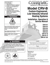
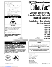
Roberts Gorden CoRayVac CRV-B-12 Installation, Operation & Service Manual (96 pages)
Custom-Engineered, Low-Intensity Infrared Heating Systems
Brand:
Roberts Gorden
| Category:
Heating System
| Size: 13.66 MB
Table of Contents
Table of Contents
3
SECTION 1: Heater Safety
9
Manpower Requirements
9
Safety Labels and Their Placement
9
California Proposition 65
9
Figure 1: Side Panel Label Placement
10
Figure 2: Top and Back Panel Label Placement
11
SECTION 2: Installer Responsibility
12
Wall Tag
12
Corrosive Chemicals
12
National Standards and Applicable Codes
12
SECTION 3: Clearances to Combustibles
13
Required Clearances to Combustibles
13
Figure 3: Level Reflector
14
Figure 4: One Side Reflector
14
Figure 5: Two Side Reflectors
14
Figure 6: Universal Shield (with and Without Holes), Position 1
15
Figure 7: Universal Shield (with and Without Holes), Position 2
15
Figure 8: Universal Shield (with and Without Holes), Position 3
15
Figure 9: 2-Foot Deco Grille
16
Figure 10: Barrier Shield
16
Figure 11: Protective Grille
16
SECTION 4: National Standards and Applicable Codes
17
Gas Codes
17
Aircraft Hangars
17
Public Garages
17
Electrical
17
Venting
17
High Altitude
17
SECTION 5: Major Components
18
Figure 12: Major Component Descriptions - Standard Reflector
18
Figure 13: Major Component Descriptions - Standard Reflector (Continued)
19
Figure 14: Classic System Component Descriptions - Standard or High Efficiency Reflector
19
Figure 15: Major Component Descriptions - High Efficiency Reflector
20
Figure 16: Major Component Descriptions - High Efficiency Reflector (Continued)
21
Figure 17: Optional Heater Accessories
22
Figure 18: Pumps and Controls Descriptions
23
Standard Parts List
24
SECTION 6: Design Requirements
26
Figure 19: Heater Assembly Overview
27
SECTION 7: Heater Installation
28
Figure 20: Critical Hanger Placement
29
Coupling and Tube Assembly
31
Tube Installation
31
Reflector Installation
33
Burner Installation
36
SECTION 8: Optional Heater Accessories
37
U-Tube Configuration
37
Tee Installation
38
Figure 22: U-Tube Heater Assembly Overview
38
Reflector Joint
39
Figure 23: Reflector Joint Detail
40
Reflector Side Extension
41
Universal Shield
42
Barrier Shield
42
Two-Foot Decorative Grille Installation
43
Protective Grille Installation
45
SECTION 9: Pump Installation and Venting
46
Pump Installation
46
Figure 24: Condensate Valve Assembly (EP-100 and
46
Figure 25: EP-200 Condensate Valve Assembly
47
Figure 26: Condensate Neutralization Tube
49
General Venting Requirements Model EP-100, EP-200 and EP-300 Series Pumps
50
Figure 27: Vertical Venting Configuration
51
Figure 28: EP-100 and EP-200 Horizontal Venting Configurations
52
Figure 29: EP-300 Series Horizontal Venting Configurations
53
SECTION 10: Outside Air Supply
54
Pressurized
54
Non-Pressurized
54
Outside Air Blower Internal Wiring
55
Figure 30: Duct Sizing
55
Figure 31: Outside Air Blower Internal Wiring Diagram
55
Figure 32: Filter Housing Assembly
56
Figure 33: Air Supply Blower Support
56
Figure 34: Pressurized Outside Air Supply
57
Figure 35: Non-Pressurized Outside Air Supply
57
SECTION 11: Gas Piping
58
Figure 36: Gas Connection with Flexible Gas Hose
59
SECTION 12: Control Methods
60
CORAYVAC Heating Control
60
CORAYVAC Modulating Heating Control (CRV-B 6/8/9/10/12/12A Only)
60
CORAYVAC Modulating Thermostat
60
DPDT Transformer Relay (P/N 90436300)
61
Figure 37: One Zone Operation Without Control Panel (Optional)
62
Figure 38: One Zone Operation (with Outside Air Blower) Without Control Panel (Optional)
63
Figure 39: Two Zone Operation Without Control Panel (Optional)
64
Figure 40: General System Wiring
65
Figure 41: External Wiring Diagram EP-100 and EP-201 120 V 1 Ø Pump
65
Figure 42: External Wiring Diagram EP-100, EP-201 or EP-301 230 V 1 Ø Pump (Optional)
66
Figure 43: External Wiring Diagram EP-203 or EP-303 208 - 230 V (or 460 V) 3 Ø Pump (Optional)
67
Figure 44: CORAYVAC
68
Figure 45: CORAYVAC
69
Figure 46: Burner Internal Wiring
70
Figure 47: Burner Internal Ladder Diagram
70
SECTION 13: Starting the System
71
Checking the Gas Line
71
Checking the Electrical System
71
Starting the System
71
Setting the Vacuum
72
Figure 48: Vacuum Reading
73
SECTION 14: Variable Frequency Drive Programming for Use with CORAYVAC Modulating Heating Control
74
VFD Parameter Settings for Use with CORAYVAC
74
Modulating Heating Control
74
Altering VFD Parameters for Use with CORAYVAC
75
Modulating Heating Control
75
SECTION 15: Variable Frequency Drive Programming for Use with CORAYVAC
76
System with Modulating Thermostat
76
VFD Parameter Settings for Use with Modulating Thermostats
76
Altering VFD Parameters for Use with CORAYVAC
77
System with Modulating Thermostat
77
Modulating System
78
Setting the CORAYVAC End Burner Vacuum
78
Adjusting the Variable Frequency Drive
78
Figure 49: Possible Damper Couplings' Locations
79
SECTION 17: Operation and Maintenance
80
Sequence of Operation
80
To Shut off Heater
80
To Start Heater
80
Pre-Season Maintenance and Annual Inspection
80
Maintenance Checklist
81
SECTION 18: Troubleshooting
83
Troubleshooting Flow Chart
84
SECTION 19: Replacement Parts
86
Replacement Parts Instructions
88
SECTION 20: General Specifications
89
Material Specifications
89
Heater Specifications
89
Suspension Specifications
89
Controls Specifications
89
SECTION 21: the ROBERTS GORDON CORAYVAC Limited Warranty
91
Advertisement
Roberts Gorden CoRayVac CRV-B-12 Installation, Operation & Service Manual (94 pages)
Custom-Engineered, Low-Intensity Infrared Heating Systems
Brand:
Roberts Gorden
| Category:
Heating System
| Size: 13.55 MB
Table of Contents
Table of Contents
3
SECTION 1: Heater Safety
7
Manpower Requirements
7
Safety Labels and Their Placement
7
California Proposition 65
7
Figure 1: Side Panel Label Placement
8
Figure 2: Top and Back Panel Label Placement
9
SECTION 2: Installer Responsibility
10
Wall Tag
10
Corrosive Chemicals
10
National Standards and Applicable Codes
10
SECTION 3: Clearances to Combustibles
11
Required Clearances to Combustibles
11
Figure 3: Standard Reflector
12
Figure 4: One Side Reflector
12
Figure 5: Two Side Reflectors
12
Figure 6: Universal Shield, Position 1
13
Figure 7: Universal Shield, Position 2
13
Figure 8: Universal Shield, Position 3
13
Figure 9: 2-Foot Deco Grille
14
Figure 10: Barrier Shield
14
Figure 11: Protective Grille
14
SECTION 4: National Standards and Applicable Codes
15
Gas Codes
15
Aircraft Hangars
15
Public Garages
15
Electrical
15
Venting
15
High Altitude
15
SECTION 5: Major Components
16
Figure 12: Major Component Descriptions
16
Standard Parts List
19
Table 1: Contents of CRV-Series Burner Carton
19
Table 2: Common CRV-Series Components
19
SECTION 6: Design Requirements
22
Figure 13: Heater Assembly Overview
23
SECTION 7: Heater Installation
24
Figure 14: Critical Hanger Placement
25
Coupling and Tube Assembly
26
Tube Installation
26
Elbow Package Configuration
27
Reflector Installation
28
Burner Installation
31
SECTION 8: Optional Heater Accessories
32
Tee Installation
32
Reflector Joint
33
Figure 15: Reflector Joint Detail
34
Reflector Side Extension
35
Universal Shield
36
Barrier Shield
36
Two-Foot Decorative Grille Installation
37
Protective Grille Installation
39
Classic Cast-Iron Components
40
SECTION 9: Pump Installation and Venting
41
Pump Installation
41
Figure 16: EP-200 Condensate Valve Assembly
41
General Venting Requirements Model
43
And EP-300 Series Pumps
43
Figure 17: Condensate Neutralization Tube
43
Figure 18: Vertical Venting Configuration
45
Horizontal Venting 4" (10 CM) Pipe
46
Figure 19: EP-100 Horizontal Venting Configurations
46
Figure 20: EP-200 Series Horizontal Venting Configurations
47
Figure 21: EP-300 Series Horizontal Venting Configurations
48
SECTION 10: Outside Air Supply
49
Pressurized
49
Non-Pressurized
49
Outside Air Blower Internal Wiring
50
Figure 22: Duct Sizing
50
Figure 23: Outside Air Blower Internal Wiring Diagram
50
Figure 24: Filter Housing Assembly
51
Figure 25: Air Supply Blower Support
51
Figure 26: Pressurized Outside Air Supply
52
Figure 27: Non-Pressurized Outside Air Supply
52
SECTION 11: Gas Piping
53
Figure 28: Gas Connection with Flexible Gas Hose
54
SECTION 12: Control Methods
55
ROBERTS GORDON System Control
55
Roberts Gordon Ultravac
55
CORAYVAC Modulating Controls
55
Figure 29: VFD Terminal Strip
57
Table 3: Modulating Thermostat Cable Requirements
57
SPST Transformer Relay Kit (P/N 90417600K)
58
SPDT Transformer Relay (P/N 90436300)
58
Figure 30: One Zone Operation Without Control Panel (Optional)
59
Figure 31: One Zone Operation (with Outside Air Blower) Without Control Panel (Optional)
60
Figure 32: Two Zone Operation Without Control Panel (Optional)
61
Figure 33: General System Wiring
62
Figure 34: External Wiring Diagram EP-100 and EP-201 120 V 1 Ø Pump
62
Figure 35: External Wiring Diagram EP-100, EP-201 or EP-301 230 V 1 Ø Pump (Optional)
63
Figure 36: External Wiring Diagram EP-203 or EP-303 208 - 230 V (or 460 V) 3 Ø Pump (Optional)
64
Figure 37: CORAYVAC Modulating Wiring Diagram [Lonworks (2-10 VDC with 500 Ohm Resistor) Optional]
65
VDC with 500 Ohm Resistor
65
Figure 38: CORAYVAC ® Modulating Wiring Diagram
66
Ma) Optional
66
Figure 39: CORAYVAC
67
Modulating with Bacnet
67
Figure 40: Burner Internal Wiring
68
Figure 41: Burner Internal Ladder Diagram
68
SECTION 13: Starting the System
69
Checking the Gas Line
69
Checking the Electrical System
69
Starting the System
69
Setting the Vacuum
69
Figure 42: Vacuum Reading
71
SECTION 14: Variable Frequency Drive Programming
72
VFD Parameter Settings for Use with Modulating Thermostats
72
Altering VFD Parameters
73
SECTION 15: Commissioning the CORAYVAC Modulating System
74
Setting the CORAYVAC End Burner Vacuum
74
Adjusting the Variable Frequency Drive
74
Programming of Variable Frequency Drive
75
Figure 43: Possible Damper Couplings' Locations
76
SECTION 16: Operation and Maintenance
77
Sequence of Operation
77
To Shut off Heater
77
To Start Heater
77
Pre-Season Maintenance and Annual Inspection
77
Maintenance Checklist
78
SECTION 17: Troubleshooting
80
Troubleshooting Flow Chart
81
SECTION 18: Replacement Parts
83
Variable Frequency Drive Replacement Parts
85
Figure 44: Variable Frequency Drive Components Diagram
85
Replacement Parts Instructions
86
SECTION 19: General Specifications
87
Material Specifications
87
Heater Specifications
87
Suspension Specifications
87
Controls Specifications
87
SECTION 20: the ROBERTS GORDON CORAYVAC Limited Warranty
89
Roberts Gorden CoRayVac CRV-B-12 Installation & Operation Manual (72 pages)
Custom-Engineered, Low-Intensity Infrared Heating Systems Installation, Operation & Service Manual
Brand:
Roberts Gorden
| Category:
Heating System
| Size: 11.54 MB
Table of Contents
Table of Contents
3
SECTION 1: Heater Safety
7
Manpower Requirements
7
SECTION 2: Installer Responsibility
8
Wall Tag
8
Corrosive Chemicals
8
National Standards and Applicable Codes
8
SECTION 3: Critical Considerations
9
Required Clearances to Combustibles
9
Figure 1: Standard Reflector
10
Figure 2: One Side Reflector
10
Figure 3: Two Side Reflectors
10
Figure 4: Universal Shield, Position 1
11
Figure 5: Universal Shield, Position 2
11
Figure 6: Universal Shield, Position 3
11
Figure 7: 2-Foot Deco Grille
12
Figure 8: Barrier Shield
12
Figure 9: 1-Foot Deco Grille
12
SECTION 4: National Standards and Applicable Codes
13
Gas Codes
13
Aircraft Hangars
13
Public Garages
13
Electrical
13
Venting
13
High Altitude
13
SECTION 5: Major Components
14
Figure 10: Major Component Descriptions
14
Standard Parts List
17
SECTION 6: Design Requirements
19
Figure 11: Heater Assembly Overview
20
SECTION 7: Heater Installation
21
Figure 12: Critical Hanger Placement
21
Coupling and Tube Assembly
22
Tube Installation
22
Elbow Package Configuration
23
Reflector Installation
24
Burner Installation
26
SECTION 8: Optional Heater Accessories
27
Tee Installation
27
Reflector Joint
27
Figure 13: Reflector Joint Detail
28
Reflector Side Extension
29
Universal Shield
30
Barrier Shield
30
Two-Foot Decorative Grille Installation
31
One-Foot Decorative Grille Installation
32
Protective Grille Installation
35
Classic Cast-Iron Components
36
SECTION 9: Pump Installation and Venting
37
Pump Installation
37
Figure 14: EP-200 Condensate Valve Assembly
37
General Venting Requirements Model EP-100, EP-200 and EP-300 Series Pumps
38
Figure 15: Vertical Venting Configuration
39
Horizontal Venting 4" (10 CM) Pipe
40
Figure 16: EP-100 Horizontal Venting Configurations
40
Figure 17: EP-200 Series Horizontal Venting Configurations
41
Figure 18: EP-300 Series Horizontal Venting Configurations
42
SECTION 10: Outside Air Supply
43
Pressurized
43
Non-Pressurized
43
Figure 19: Duct Sizing
43
Outside Air Blower Internal Wiring
44
Figure 20: Outside Air Blower Internal Wiring Diagram
44
Figure 21: Filter Housing Assembly
44
Figure 22: Air Supply Blower Support
45
Figure 23: Pressurized Outside Air Supply
45
Figure 24: Non-Pressurized Outside Air Supply
46
SECTION 11: Gas Piping
47
Figure 25: Gas Connection with Flexible Gas Hose
47
SECTION 12: Control Methods
48
ROBERTS GORDON System Control
48
Roberts Gordon Ultravac
48
SPST Transformer Relay (P/N 90417600)
48
DPST Transformer Relay (P/N 90436300)
48
Figure 26: One Zone Operation Without Control Panel
49
Figure 27: One Zone Operation (with Outside Air Blower) Without Control Panel
50
Figure 28: Two Zone Operation Without Control Panel
51
Figure 29: General System Wiring
52
Figure 30: External Wiring Diagram EP-100 and EP-201 120 V 1 Ø Pump
52
Figure 31: External Wiring Diagram EP-301 120 V 1 Ø Pump
53
Figure 32: External Wiring Diagram EP-203 or EP-303 208 V - 230 V (or 460 V) 3 Ø Pump
53
Figure 33: Burner Internal Wiring
54
Figure 34: Burner Internal Ladder Diagram
54
SECTION 13: Starting the System
55
Checking the Gas Line
55
Checking the Electrical System
55
Starting the System
55
Setting the Vacuum
55
Figure 35: Vacuum Reading
56
SECTION 14: Operation and Maintenance
57
Sequence of Operation
57
To Shut off Heater
57
To Start Heater
57
Pre-Season Maintenance and Annual Inspection
57
Maintenance Checklist
58
SECTION 15: Troubleshooting
61
Troubleshooting Flow Chart
61
SECTION 16: Replacement Parts
63
SECTION 17: General Specifications
64
Material Specification
64
Heater Specifications
64
Suspension Specifications
64
Controls Specifications
64
SECTION 18: the ROBERTS GORDON CORAYVAC Limited Warranty
67
Advertisement
Roberts Gorden CoRayVac CRV-B-12 Design Manual (40 pages)
Custom Engineered, Gas-Fired, Low-Intensity Infrared Heating System
Brand:
Roberts Gorden
| Category:
Heating System
| Size: 2.65 MB
Table of Contents
Table of Contents
3
SECTION 1: Concept
7
SECTION 2: the CRV-Series System
8
Safety
8
Zero Regulator
8
Figure 1: Assembly Overview (Two Branch System Shown)
9
Fuel Savings and Comfort
10
SECTION 3: Clearances to Combustibles
11
Required Clearances to Combustibles
11
Figure 2: Standard Reflector
12
Figure 3: One Side Reflector
12
Figure 4: Two Side Reflectors
12
Figure 5: Universal Shield, Position 1
13
Figure 6: Universal Shield, Position 2
13
Figure 7: Universal Shield, Position 3
13
Figure 8: 2-Foot Deco Grille
14
Figure 9: Barrier Shield
14
Figure 10: Protective Grille
14
SECTION 4: Sizing and Design Considerations
15
Radiant Adjustment to Heat Loss
15
Radiant Height Adjustment Factor
15
Selecting the Burners
16
Radiant Distribution
16
Figure 11: Radiant Distribution (Average Coverage)
17
Figure 12: Radiant Distribution (Increased Coverage)
17
Figure 13: Radiant Distribution (Heavy Coverage)
17
SECTION 5: Flow Loading
18
Radiant Branch Flow
18
Table 1: CORAYVAC Design Parameters
18
Figure 14: Burner Flow Units
19
Pump Capacity
20
Tailpipe Flow
20
Figure 15: Vacuum Loss Curve for 4" Shared Tailpipe
20
Table 2: Pump Capacity
20
Table 3: Pump Exhaust Requirements
20
SECTION 6: Radiant Tube and Tailpipe
21
Radiant Tube Length
21
Tailpipe
21
Design Parameters
22
CRV-Series Design Methods
22
Figure 16: Tube Length Vs. Efficiency
22
Table 4: Allowable Tailpipe Lengths
23
Tailpipe Design Method
24
Table 5: Operating Characteristics; Condensing or Non-Condensing
24
Figure 17: Possible Damper Coupling Locations
26
SECTION 7: Example CRV-Series System Layouts
27
Example System Layout (Option 1)
27
Figure 18: Example System Layout (Option 1)
27
Example System Layout (Option 2)
28
Example System Layout (Option 3)
28
Figure 19: Example System Layout (Option 2)
28
Figure 20: Example System Layout (Option 3)
28
Example System Layout (Option 4)
29
Example System Layout (Option 5)
29
Figure 21: Example System Layout (Option 4)
29
Figure 22: Example System Layout (Option 5)
29
Example System Layout (Option 6)
30
Figure 23: Example System Layout (Option 6)
30
Figure 24: Example System Layout (Option 7)
30
Figure 25: Example System Layout (Option 8)
30
Example System Layout (Option 7, 8 and 9)
31
Figure 26: Example System Layout (Option 9)
31
SECTION 8: Control Methods
32
ROBERTS GORDON ® System Control
32
Roberts Gordon ® Ultravac
32
CORAYVAC ® Modulating Controls
32
SPST Transformer Relay Kit (P/N 90417600K)
33
SPDT Transformer Relay (P/N 90436300)
33
Pressure Switch
33
SECTION 9: Air Supply System
34
Pressurized
34
Non-Pressurized
34
Outside Air System Design Requirements
34
Figure 27: Air Supply System Capacity by Duct Length and
34
Figure 28: Outside Air Blower
35
Figure 29: Sample Layout for Pressurized Outside Air
36
SECTION 10: ROBERTS GORDON ULTRAVAC Design
37
Requirements
37
SECTION 11: CRV-Series Equipment Specifications
38
Burner and Burner Controls
38
Equipment
38
Roberts Gorden CoRayVac CRV-B-12 Design Manual (40 pages)
Custom Engineered, Gas-Fired, Low-Intensity Infrared Heating System
Brand:
Roberts Gorden
| Category:
Heating System
| Size: 2.44 MB
Table of Contents
Table of Contents
3
SECTION 1: Concept
7
SECTION 2: the CRV-Series System
8
Safety
8
Zero Regulator
8
Figure 1: Assembly Overview (Two Branch System Shown)
9
Fuel Savings and Comfort
10
SECTION 3: Clearances to Combustibles
11
Required Clearances to Combustibles
11
Figure 2: Standard Reflector
12
Figure 3: One Side Reflector
12
Figure 4: Two Side Reflectors
12
Figure 5: Universal Shield, Position 1
13
Figure 6: Universal Shield, Position 2
13
Figure 7: Universal Shield, Position 3
13
Figure 8: 2-Foot Deco Grille
14
Figure 9: Barrier Shield
14
Figure 10: Protective Grille
14
SECTION 4: Sizing and Design Considerations
15
Radiant Adjustment to Heat Loss
15
Radiant Height Adjustment Factor
15
Selecting the Burners
16
Radiant Distribution
16
Figure 11: Radiant Distribution (Average Coverage)
17
Figure 12: Radiant Distribution (Increased Coverage)
17
Figure 13: Radiant Distribution (Heavy Coverage)
17
SECTION 5: Flow Loading
18
Radiant Branch Flow
18
Table 1: CORAYVAC Design Parameters
18
Figure 14: Burner Flow Units
19
Pump Capacity
20
Tailpipe Flow
20
Figure 15: Vacuum Loss Curve for 4" Shared Tailpipe
20
Table 2: Pump Capacity
20
Table 3: Pump Exhaust Requirements
20
SECTION 6: Radiant Tube and Tailpipe
21
Radiant Tube Length
21
Tailpipe
21
Design Parameters
22
CRV-Series Design Methods
22
Figure 16: Tube Length Vs. Efficiency
22
Table 4: Allowable Tailpipe Lengths
23
Tailpipe Design Method
24
Table 5: Operating Characteristics; Condensing or Non-Condensing
24
Figure 17: Possible Damper Coupling Locations
26
SECTION 7: Example CRV-Series System Layouts
27
Example System Layout (Option 1)
27
Figure 18: Example System Layout (Option 1)
27
Example System Layout (Option 2)
28
Example System Layout (Option 3)
28
Figure 19: Example System Layout (Option 2)
28
Figure 20: Example System Layout (Option 3)
28
Example System Layout (Option 4)
29
Example System Layout (Option 5)
29
Figure 21: Example System Layout (Option 4)
29
Figure 22: Example System Layout (Option 5)
29
Example System Layout (Option 6)
30
Figure 23: Example System Layout (Option 6)
30
Figure 24: Example System Layout (Option 7)
30
Figure 25: Example System Layout (Option 8)
30
Example System Layout (Option 7, 8 and 9)
31
Figure 26: Example System Layout (Option 9)
31
SECTION 8: Control Methods
32
Roberts Gordon (P/N 02770002)
32
ROBERTS GORDON System Control (P/N 02770002)
32
Roberts Gordon Ultravac
32
SPST Transformer Relay (P/N 90417600K)
33
DPST Transformer Relay (P/N 90436300)
33
Pressure Switch
33
SECTION 9: Air Supply System
34
Pressurized
34
Non-Pressurized
34
Outside Air System Design Requirements
34
Figure 27: Air Supply System Capacity by Duct Length and Diameter
34
Figure 28: Outside Air Blower
35
Figure 29: Sample Layout for Pressurized Outside Air Systems
36
SECTION 10: ROBERTS GORDON ULTRAVAC Design Requirements
37
SECTION 11: CRV-Series Equipment Specifications
38
Burner and Burner Controls
38
Equipment
38
Roberts Gorden CoRayVac CRV-B-12 Installation, Operation & Service Manual (61 pages)
Custom-Engineered, Low-Intensity Infrared Heating Systems
Brand:
Roberts Gorden
| Category:
Heating System
| Size: 9.13 MB
Table of Contents
Table of Contents
3
1 Heater Safety
5
2 Installer Responsibility
5
3 Critical Considerations
6
Minimum Required Clearances to Combustibles
6
Clearances to Combustibles
7
Barrier Shield
9
4 National Standards and Applicable Codes
10
Gas Codes
10
Aircraft Hangars
10
Public Garages
10
Electrical
10
Venting
10
5 Standard Parts List
11
6 Design Requirements
13
7 Assembly Overview
14
CRV Assembly Overview
18
8 Heater Installation
19
Critical Hanger Placement
19
Tube Assembly
20
Coupling and Tube Assembly
20
Elbow Package
21
Reflector
22
Figure 12 Reflector Overlap Detail
23
Burner
24
Reflector Joint
24
Reflector Side Extension
26
Universal Shield
27
Barrier Shield
28
Decorative Grille
29
1-Foot Deco Grille
30
Protective Grille
33
CORAYVAC Classic Cast Iron Components
35
9 Pump Installation and Venting
36
General Venting Requirements
36
Vertical Venting
37
Horizontal Venting Configurations
38
Figure 16 EP-201/203 Horizontal Venting
39
Figure 17 EP-301/303 Horizontal Venting
40
10 Outside Air Supply
41
Figure 19 Filter Housing Assembly
42
Figure 21 Outside Air Supply-Pressurized
43
11 Gas Piping
44
12 Control Methods
45
Figure 24 One Zone Operation
47
Figure 25 Two Zone Operation
48
Figure 26 General System Wiring
49
V 1Ph Pump
50
Figure 30 CRV Burner Internal Wiring
51
Figure 32 Vacuum Reading
52
13 Operation and Maintenance
53
Sequence of Operation
53
Start up Procedure
53
14 Troubleshooting
56
Troubleshooting Flow Chart
56
15 Replacement Parts
58
16 General Specifications
59
18 Limited Warranty
61
Roberts Gorden CoRayVac CRV-B-12 Installation & Operation Manual (41 pages)
CRV-Series Custom-Engineered, Low-Intensity Infrared Heating Systems
Brand:
Roberts Gorden
| Category:
Heating System
| Size: 8.57 MB
Table of Contents
Standard Parts List
2
Contents of CRV-Series Burner Carton
2
Common CRV-Series Components
2
General Specifications
5
Pump Specifications
6
Clearances to Combustibles
7
Roberts Gordon Ultravac
12
Heater Installation
14
Critical Hanger Placement
14
Tube Installation
15
Coupling and Tube Assembly
15
Elbow Package Configuration
16
Elbow Installation
16
Reflector Installation
17
Burner Installation
19
Optional Heater Accessories
20
Tee Installation
20
Reflector Side Extension
22
Bracket Installation
22
Universal Shield
23
Barrier Shield
23
Two-Foot Decorative Grille Installation
24
One-Foot Decorative Grille Installation
25
Decorative Grille
26
Protective Grille Installation
28
Silicone Cap Installation
28
Grille End Cap Installation
28
Pump Installation
30
Outside Combustion Air Supply
33
Filter Housing Assembly
33
Air Supply Blower Support
33
Non-Pressurized Outside Air Supply
34
Gas Piping
35
Gas Connection with Stainless Steel Flex Gas Connector
35
One Zone Operation Without Control Panel
36
Two Zone Operation Without Control Panel
37
The Roberts Gordon
40
Limited Warranty
40
Advertisement
Related Products
Roberts Gorden CRV-Series
Roberts Gorden CoRayVac CRV-B-4
Roberts Gorden CoRayVac CRV-B-6
Roberts Gorden CoRayVac CRV-B-10
Roberts Gorden CoRayVac CRV-B-8
Roberts Gorden CoRayVac CRV-B-9
Roberts Gorden CoRayVac CRV-B-12A
Roberts Gorden CoRayVac CRV-B-2
Roberts Gorden CoRayVac CRT-25
Roberts Gorden CoRayVac CRT-20
Roberts Gorden Categories
Heater
Heating System
Electric Heater
Gas Heater
Water Pump
More Roberts Gorden Manuals
Login
Sign In
OR
Sign in with Facebook
Sign in with Google
Upload manual
Upload from disk
Upload from URL