Sign In
Upload
Manuals
Brands
Panasonic Manuals
Transmitter
SE-FX65P
Panasonic SE-FX65P Manuals
Manuals and User Guides for Panasonic SE-FX65P. We have
2
Panasonic SE-FX65P manuals available for free PDF download: Service Manual
Panasonic SE-FX65P Service Manual (145 pages)
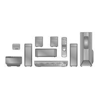
DVD Home Theater Sound System
Brand:
Panasonic
| Category:
Home Theater System
| Size: 7.71 MB
Table of Contents
Specifications
1
Table of Contents
3
1 Safety Precautions
5
General Guidelines
5
Before Repair and Adjustment
5
Protection Circuitry
5
Safety Parts Information
6
2 Prevention of Electrostatic Discharge (ESD) to
7
Electrostatically Sensitive (ES) Devices
7
3 Precaution of Laser Diode
8
4 About Lead Free Solder (Pbf)
9
Service Caution Based on Legal Restrictions
9
5 Handling Precautions for Traverse Unit
10
Cautions to be Taken in Handling the Optical Pickup Unit
10
Grounding for Electrostatic Breakdown Prevention
10
6 Accessories
12
7 Operation Procedures
13
Remote Control Key Buttons Operations
13
Main Unit Key Buttons Operations
14
Wireless Surround
15
Using the VIERA Link "HDAVI Control
16
Using the Music Port
17
Disc Information
18
8 New Features
20
About HDMI
20
Wireless Features
22
Block Diagram
23
9 Self-Diagnosis and Special Mode Setting
29
Service Mode Summary Table
29
Service Mode Table (Main Unit)
29
Wireless Service Mode Summary Table
39
Service Mode Table (Wireless)
40
DVD Self Diagnostic Function-Error Code
42
Sales Demonstration Lock Function
44
Service Precautions
45
10 Assembling and Disassembling
47
Disassembly Flow Chart
49
Main Components and P.C.B. Locations
50
Disassembly of Top Cabinet
51
Disassembly of Tray Lid Assembly
51
Disassembly of Front Panel
51
Disassembly of Panel P.C.B. & Key P.C.B
52
Dissassembly of Tray Base Assembly
52
Disassembly of Mechanism Base Assembly
53
Disassembly of Rear Panel
53
Disassembly of Wireless Adapter
54
Disassembly of Tray
54
Disassembly of D-Amp P.C.B
55
Disassembly of Digital Amp IC (IC5000)
55
Disassembly of DVD Module P.C.B
56
Disassembly of Main P.C.B
56
Disassembly of Regulator IC (IC2903)
57
Disassembly of SMPS & AC-Inlet P.C.B
58
Disassembly of Switch Regulator IC (IC5701)
58
Disassembly of Regulator Diode (D5803)
59
Disassembly of Regulator Diode (D5801/D5802)
59
Disassembly of Regulator Diode (D5702)
60
Disassembly of Tray Guide (L) & Tray Guide (R)
60
Disassembly of Rotary Tray
61
Disassembly of Open Lock Gear
61
Disassembly of Close Lock Gear
61
Disassembly of Tray Motor P.C.B
62
Disassembly of Sensor P.C.B
62
Disassembly of Traverse Unit
62
Disassembly of Pulley Gear
63
Disassembly of Loading Motor P.C.B
64
Disassembly of Drive Gear (A) & Drive Gear (B)
64
Disassembly of Magnet Holder, Washer, Magnet
64
Clamper
64
Disassembly of Support Piece, Change Lever, Slide Plate
65
(L) & Slide Plate (R)
65
Disassembly of Cam Gear
66
Assembly of Tray Base Assembly
66
11 Service Fixture and Tools
68
12 Service Positions
68
Checking & Repair Panel P.C.B. & Key P.C.B
68
Checking & Repair Main P.C.B
68
Checking & Repair SMPS P.C.B
69
Checking & Repair D-Amp P.C.B
69
Checking & Repair DVD Module P.C.B
70
13 Measurements and Adjustments
71
Service Tools and Equipment
71
Important Points in Adjustment
71
Storing and Handling of Test Discs
71
Optical Adjustment
72
14 Abbreviations
73
15 Voltage and Waveform Chart
75
DVD Module P.C.B
75
Main P.C.B
77
D-Amp P.C.B
78
Smps P.C.b
78
Panel P.C.B
78
Tray, Loading Motor, Tray Motor & Sensor P.C.B
79
Waveform Chart
80
16 Illustration of IC's, Transistors and Diodes
82
17 Wiring Connection Diagram
85
18 Block Diagram
87
System Control
87
DVD (Servo)
88
DVD (Video/Audio)
89
DVD Interface
90
Audio
91
Audio Digital Amp
92
Power
93
19 Schematic Diagram Notes
95
20 Schematic Diagram
97
DVD Module (DV5/HDMI) Circuit
97
Main Circuit & Panel
102
D-Amp & SMPS Circuit
107
Tray Circuit
111
Key, Wireless Adapter, AC-Inlet & Loading Motor Circuit
112
Tray Motor, Sensor & Optical Pickup Unit Circuit
113
21 Printed Circuit Board
115
DVD Module P.C.B
115
Main P.C.B
116
Panel, Key & Wireless Adapter
117
D-Amp
118
D-Amp P.C.B
118
Smps
119
AC-Inlet, Tray, Loading Motor, Tray Motor & Sensor
120
22 Basic Troubleshooting Guide
121
Basic Troubleshooting Guide for Traverse Unit (DVD Module P.C.B)
121
Basic Troubleshooting Guide for HDMI AV Output
122
23 Overall Block Diagram for PT750
124
SC-PT750 Main Circuit Block
124
SC-PT750 SMPS Circuit Block
125
24 Terminal Function of Ics
126
IC2001 (C2CBYY000472): System Control IC
126
25 Exploded Views
127
Cabinet Parts Location
129
Packaging
131
Replacement Parts List
132
Component Parts List
133
Advertisement
Panasonic SE-FX65P Service Manual (65 pages)
Wireless System and Digital Transmitter
Brand:
Panasonic
| Category:
Transmitter
| Size: 4.22 MB
Table of Contents
Table of Contents
2
1 Note
3
Packaging
3
System Combination Breakdown
3
2 Safety Precautions
4
General Guidelines
4
Before Repair and Adjustment (Digital Receiver SE-FX65)
4
Protection Circuitry
5
Safety Part Information
5
Prevention of Electro Static Discharge (ESD) to
6
3 Prevention of Electro Static Discharge (ESD) to Electrostatically Sensitive (ES) Devices
6
4 Handling the Lead-Free Solder
7
Service Caution Based on Legal Restrictions
7
5 Accessories
8
6 Using of Digital Receiver Unit
9
Connecting the Digital Transmitter (SH-FX65T)
9
Connecting the Surround Speaker Cables to the Wireless System (SE-FX65)
9
AC Power Cord Connection (SE-FX65)
9
Making the Wireless Link (SE-FX65)
10
7 Operation Procedures
11
Remote Control Key Buttons Operations
11
Main Unit Key Buttons Operations
12
8 New Features
13
Wireless Features
13
Led Indication
15
9 Self-Diagnosis and Special Mode Setting
20
Wireless Service Mode Summary Table
20
Service Mode Table (Wireless)
21
10 Assembling and Disassembling
23
Note
23
Disassembly Flow Chart (for SE-FX65)
24
Main Parts Location Diagram
24
Disassembly of Wireless System (SE-FX65P/PC)
25
Disassembly of Transmitter Module P.C.B (SH-FX65T)
28
11 Service Positions
29
P.C.b
29
12 Voltage Measurement & Waveform Chart
30
Voltage Measurement
30
Waveform Chart
31
13 Wiring Connection Diagram
32
14 Block Diagram
33
Digital Amplifier/Led Drive/Led Block Diagram
33
Receiver Module Block Diagram
34
Transmitter Module Block Diagram
35
15 Notes of Schematic Diagram
37
16 Schematic Diagram
39
DAMP CIRCUIT, LED DRIVE CIRCUIT and LED CIRCUIT
39
Receiver Module Circuit
41
Transmitter Module Circuit
45
17 Printed Circuit Board Diagram
49
DAMP P.C.B, LED DRIVE P.C.B, LED P.C.B and
49
Receiver Module P.C.b
49
Transmitter Module P.C.b
50
18 Illustration of IC's, Transistors and Diodes
51
19 Terminal Functions of Integrated Circuits
52
Ic10 (C1Ab00002772): IC Base Band
52
Ic13 (C1Cb00002648): IC Rf
52
Ic1000 (C2Bbed000056): IC Mcu
53
20 Exploded Views
55
Cabinet Parts Location
55
Packaging
56
21 Service Hint
59
Tx / Rx Kit Assembly
59
Tx Case Assembly
59
22 Replacement Parts List
60
Parts List (SE-FX65)
60
Parts List (SH-FX65T)
63
Advertisement
Related Products
Panasonic SE-FX65PC
Panasonic SH-FX65P
Panasonic SH-FX65PC
Panasonic SH-FX65TPP
Panasonic SE-FX70
Panasonic SE-FX65
Panasonic SE-FX67
Panasonic SE-FX50
Panasonic SE-FX65A
Panasonic SE-FX66
Panasonic Categories
Air Conditioner
Camcorder
TV
Digital Camera
Cordless Telephone
More Panasonic Manuals
Login
Sign In
OR
Sign in with Facebook
Sign in with Google
Upload manual
Upload from disk
Upload from URL