Sign In
Upload
Manuals
Brands
Omron Manuals
Control Unit
CPM2C-SRT21
Omron CPM2C-SRT21 Manuals
Manuals and User Guides for Omron CPM2C-SRT21. We have
2
Omron CPM2C-SRT21 manuals available for free PDF download: Operation Manual
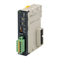
Omron CPM2C-SRT21 Operation Manual (425 pages)
CompoBus/S
Brand:
Omron
| Category:
Control Unit
| Size: 8 MB
Table of Contents
OMRON Product References
5
Visual Aids
5
Table of Contents
7
Read and Understand this Manual
11
Warranty and Limitations of Liability
11
Application Considerations
12
Suitability for Use
12
Dimensions and Weights
13
Performance Data
13
Errors and Omissions
13
Precautions
15
Intended Audience
16
General Precautions
16
Safety Precautions
16
Operating Environment Precautions
17
Application Precautions
18
Conformance to EC Directives
21
Applicable Directives
21
Concepts
21
System Design
23
System Overview and Features
24
System Overview
24
Network Features
25
Communications Modes
27
Compobus/S System Configuration
28
Basic System Configuration
28
Compobus/S System Components
30
Compatible Devices
32
Compatible Masters
32
Slave Units
35
Cables
38
Connectors/Terminal Blocks
39
Startup Procedure
42
Compobus/S System Specifications and Configuration
45
Communications Specifications
46
System Configuration
47
Main Line/Branch Line Connections
47
Maximum Cable Length
51
Supplying Power to the Slaves
53
Terminator Connection
53
Using 2-Conductor VCTF Cable
55
Using 4-Conductor VCTF or Special Flat Cable
56
Limitations of Communications Cable Power Supply
57
System Configuration Using Water-Resistant Terminals
63
I/O Response Time Characteristics
63
Slaves Other than Analog Terminals
64
Slave Analog Terminals
68
Slave I/O Delay Times
73
Compobus/S System Wiring
75
Mounting
76
Master Unit Mounting
76
Slave Unit Mounting
76
Connector Installation (Special Flat Cable Only)
77
Branch Connector
78
Extension Connector
81
Connector Terminator
84
VCTF Cable Assembly
86
Branching and Extending VCTF Cable
86
Installing Terminators
87
Master/Slave Connecting Cables
88
Crimp Terminal Installation
88
Master and Slave Terminal Connections
89
Cable Connector Wiring and Assembly
89
Operations Checklist
92
Master Unit Specifications and Operations
95
C200HW-SRM21-V1 Master Unit for CS-Series, C200HX/C200HG/C200HE-(Z)E, and C200HS Plcs
96
Specifications and Part Names
96
Switch Settings
98
Rotary Switch
98
I/O Allocations in CS-Series, C200HX/C200HG/C200HE-(Z)E, and C200HS Plcs
100
Data Areas in the PLC
107
CS1W-SRM21 Master Unit for CS-Series Plcs
110
Specifications and Part Names
110
Part Names and Functions
111
Switch Settings
112
I/O Allocations
114
Slave Registration Function and Communications Stop Mode
120
Allocations for Master Unit in PLC
125
CJ1W-SRM21 Master Unit for CJ-Series Plcs
126
Specifications and Part Names
126
Switch Settings
129
Wiring and Installing Communications Cables
131
I/O Allocations
136
Slave Registration Function and Communications Stop Mode
142
Allocations for Master Unit in PLC
147
CQM1-SRM21-V1 Master Unit for CQM1 Plcs
148
Specifications and Part Names
148
Switch Settings
151
I/O Allocations in CQM1 Plcs
152
SRM1-C0@-V2 Master Control Units
158
Specifications and Part Names
158
Name and Function of Parts
161
CPM2C-S Series CPM2C-S@@@C (-DRT)
162
Settings
162
Specifications and Part Names
163
Unit Specifications
163
Settings
166
Slave Specifications and Operations
167
Remote Terminals
169
SRT@@-ID@@ (-1) Remote Terminals with 4, 8, or 16 Transistor Inputs
169
SRT@-ID16T (-1) Remote Terminals with 16 Transistor Inputs (and 3-Tier Terminal Blocks)
179
SRT@-OD@@ (-1) Remote Terminals with 4, 8, or 16 Transistor Outputs
185
Specifications
185
SRT@-OD16T (-1) Remote Terminals with 16 Transistor Outputs (and 3-Tier Terminal Blocks)
195
SRT@-MD16T (-1) Remote Terminals with 8 Input and 8 Output Transistors (3-Tier Terminal Block)
201
SRT@-RO@@@ Remote Terminals with Relay/Power MOS Fets
207
Reference Data
209
Internal Circuits
213
Connector Terminals
216
With 8 Input or 16 Output Transistors
216
Dip Switch
220
Mounting Methods
234
SRT2-VOD@@@@ (-1) Connector Terminals with 8 or 16 Transistor Outputs
235
Specifications
235
Dip Switch
238
SRT2-ID32ML (-1) Connector Terminals with 32 Transistor Inputs
247
Switch Settings
250
SRT2-OD32ML (-1) Connector Terminals with 32 Transistor Outputs
258
SRT2-MD32ML (-1) Connector Terminals with 16 Transistor Inputs and 16 Transistor Outputs
268
Wiring and Assembly of Communications Connector and MIL Connector for Connector Terminals
278
Remote I/O Modules
282
SRT@-@D16P Remote I/O Modules
282
Water-Resistant Terminals
290
With 4 or 8 Transistor Inputs
290
With 4 or 8 Transistor Outputs
299
Shielded Connector Wiring and Assembly
306
Sensor Terminals
309
SRT@-@D08S Sensor Terminals with 8 Transistor Inputs or 4 Transistor Inputs and 4 Transistor Outputs
309
Sensor Compatibility
313
Internal Circuits
313
SRT@-OD08S Sensor Terminal with 8 Transistor Outputs
317
Fiber Amplifier Communications Units
323
E3X-SRT21 Fiber Amplifier Communications Unit
323
Analog Input Terminals
330
SRT2-AD04 Analog Input Terminal
330
Analog Output Terminals
340
SRT2-DA02 Analog Output Terminal
340
Specifications
341
DIP Switches
342
I/O Link Units for CPM1A and CPM2A
349
CPM1A-SRT21 I/O Link Unit for CPM1A and CPM2A
349
5-10 I/O Link Units for CPM2C
353
5-10-1 CPM2C-SRT21 I/O Link Unit for CPM2C
353
5-11 Sensor Amplifier Terminals
357
5-11-1 SRT1-T@D04S Sensor Amplifier Terminals
357
5-11-2 Sensor Amplifier Terminals
365
Sensitivity Settings
368
5-12 Application Precautions
372
5-12-1 Two-Wire DC Sensor Connections
372
5-12-2 Sensor Inrush Current
373
Turning the Power on
376
Power-Up Checklist
377
Checking Operations for CS-Series, C200HX/C200HG/C200HE-(Z)E
378
And C200HS Master Units
378
Indicators
378
Checking Status Using Status Information
379
Checking Normal Operations Using Ladder Programs
381
Troubleshooting
382
Common Mistakes
386
Checking Operations of CS-Series and CJ-Series Master Units
387
Indicators
387
Errors and Troubleshooting
387
Checking Status Using Status Information
387
Checking Status Using Special I/O Unit DM Area
389
Checking Normal Operations Using Ladder Programming
393
Troubleshooting
395
Checking Operations of CQM1 Master Units
399
Indicators
399
Error Detection with the Alarm Output (CQM1 Only)
400
Checking Normal Operations Using Ladder Programming
401
Troubleshooting
401
Checking Slave Operations
404
Indicators
404
Cleaning and Inspection
406
Cleaning
406
Inspection
406
Precautions for Replacement of Units or Parts
407
Precautions for Unit Replacement
407
Settings after Unit Replacement
407
Replacing Relays
407
Standard Models
410
Connector Terminals
410
Remote I/O Modules
411
Sensor Amplifier Terminals
411
Analog Terminals
411
Water-Resistant Terminals
412
Other Products
415
Revision History
423
Advertisement
OMRON CPM2C-SRT21 Operation Manual (423 pages)
CompoBus/S system
Brand:
OMRON
| Category:
Control Unit
| Size: 8 MB
Table of Contents
Table of Contents
6
Precautions
14
General Precautions
15
Intended Audience
15
Safety Precautions
15
Operating Environment Precautions
16
Application Precautions
17
Conformance to EC Directives
20
Section 1
22
System Design
22
System Overview and Features
23
System Overview
23
Network Features
24
Communications Modes
26
Compobus/S System Configuration
27
Basic System Configuration
27
Compobus/S System Components
29
Compatible Devices
31
Compatible Masters
31
Slave Units
34
Cables
37
Connectors/Terminal Blocks
38
Startup Procedure
41
Section 2 Compobus/S System Specifications and Configuration
44
Compobus/S System Specifications and Configuration
44
Communications Specifications
45
System Configuration
46
Main Line/Branch Line Connections
46
Maximum Cable Length
50
Supplying Power to the Slaves
52
Terminator Connection
52
Using 2-Conductor VCTF Cable
54
Using 4-Conductor VCTF or Special Flat Cable
55
Limitations of Communications Cable Power Supply
56
System Configuration Using Water-Resistant Terminals
62
I/O Response Time Characteristics
62
Slaves Other than Analog Terminals
63
Slave Analog Terminals
67
Slave I/O Delay Times
72
Section 3 Compobus/S System Wiring
74
Compobus/S System Wiring
74
Mounting
75
Master Unit Mounting
75
Slave Unit Mounting
75
Connector Installation (Special Flat Cable Only)
76
Branch Connector
77
Extension Connector
80
Connector Terminator
83
VCTF Cable Assembly
85
Branching and Extending VCTF Cable
85
Installing Terminators
86
Master/Slave Connecting Cables
87
Crimp Terminal Installation
87
Cable Connector Wiring and Assembly
88
Master and Slave Terminal Connections
88
Operations Checklist
91
Section 4 Master Unit Specifications and Operations
94
Master Unit Specifications and Operations
94
4-1 C200HW-SRM21-V1 Master Unit for CS-Series
94
C200HW-SRM21-V1 Master Unit for CS-Series, C200HX/C200HG/C200HE-(Z)E, and C200HS Plcs
95
Specifications and Part Names
95
Switch Settings
97
And C200HS Plcs
99
I/O Allocations in CS-Series, C200HX/C200HG/C200HE-(Z)E
99
Data Areas in the PLC
106
CS1W-SRM21 Master Unit for CS-Series Plcs
109
Specifications and Part Names
109
Switch Settings
111
I/O Allocations
113
Slave Registration Function and Communications Stop Mode
119
Allocations for Master Unit in PLC
124
CJ1W-SRM21 Master Unit for CJ-Series Plcs
125
Specifications and Part Names
125
Switch Settings
128
Wiring and Installing Communications Cables
130
I/O Allocations
135
Slave Registration Function and Communications Stop Mode
141
Allocations for Master Unit in PLC
146
CQM1-SRM21-V1 Master Unit for CQM1 Plcs
147
Specifications and Part Names
147
Switch Settings
150
I/O Allocations in CQM1 Plcs
151
SRM1-C0@-V2 Master Control Units
157
Specifications and Part Names
157
CPM2C-S Series CPM2C-S@@@C (-DRT)
161
Settings
161
Specifications and Part Names
162
Settings
165
Section 5 Slave Specifications and Operations
166
Slave Specifications and Operations
166
Remote Terminals
168
SRT@-ID16T (-1) Remote Terminals with 16 Transistor Inputs (and 3-Tier Terminal Blocks)
178
SRT@@-ID@@ (-1) Remote Terminals with 4, 8, or 16 Transistor Inputs
178
SRT@-OD@@ (-1) Remote Terminals with 4, 8, or 16 Transistor Outputs
184
SRT@-OD16T (-1) Remote Terminals with 16 Transistor Outputs (and 3-Tier Terminal Blocks)
194
SRT@-MD16T (-1) Remote Terminals with 8 Input and 8 Output Transistors (3-Tier Terminal Block)
200
SRT@-RO@@@ Remote Terminals with Relay/Power MOS Fets
206
Connector Terminals
215
SRT2-VID@@@@ (-1) Connector Terminals with 8 Input or 16 Output Transistors
215
SRT2-VOD@@@@ (-1) Connector Terminals with 8 or 16 Transistor Outputs
234
SRT2-ID32ML (-1) Connector Terminals
246
With 32 Transistor Inputs
246
SRT2-OD32ML (-1) Connector Terminals
257
With 32 Transistor Outputs
257
With 16 Transistor Inputs and 16 Transistor Outputs
267
Wiring and Assembly of Communications Connector and MIL Connector for Connector Terminals
277
Remote I/O Modules
281
SRT@-@D16P Remote I/O Modules
281
Water-Resistant Terminals
289
With 4 or 8 Transistor Inputs
289
With 4 or 8 Transistor Outputs
298
Shielded Connector Wiring and Assembly
305
Sensor Terminals
308
SRT@-@D08S Sensor Terminals with 8 Transistor Inputs or 4 Transistor Inputs and 4 Transistor Outputs
308
SRT@-OD08S Sensor Terminal with 8 Transistor Outputs
316
Fiber Amplifier Communications Units
322
E3X-SRT21 Fiber Amplifier Communications Unit
322
Analog Input Terminals
329
SRT2-AD04 Analog Input Terminal
329
Analog Output Terminals
339
SRT2-DA02 Analog Output Terminal
339
I/O Link Units for CPM1A and CPM2A
348
CPM1A-SRT21 I/O Link Unit for CPM1A and CPM2A
348
5-10 I/O Link Units for CPM2C
352
5-10-1 CPM2C-SRT21 I/O Link Unit for CPM2C
352
5-11 Sensor Amplifier Terminals
356
5-11-1 SRT1-T@D04S Sensor Amplifier Terminals
356
Sensor Amplifier Terminals
364
5-12 Application Precautions
371
5-12-1 Two-Wire DC Sensor Connections
371
5-12-2 Sensor Inrush Current
372
Section 6 Starting Communications
374
Starting Communications
374
Turning the Power on
375
Power-Up Checklist
376
Checking Operations for CS-Series, C200HX/C200HG/C200HE-(Z)E
377
And C200HS Master Units
377
Indicators
377
Checking Status Using Status Information
378
Checking Normal Operations Using Ladder Programs
380
Troubleshooting
381
Checking Operations of CS-Series and CJ-Series Master Units
386
Checking Status Using Status Information
386
Indicators
386
Checking Status Using Special I/O Unit DM Area
388
Checking Normal Operations Using Ladder Programming
392
Troubleshooting
394
Checking Operations of CQM1 Master Units
398
Indicators
398
Error Detection with the Alarm Output (CQM1 Only)
399
Checking Normal Operations Using Ladder Programming
400
Troubleshooting
400
Checking Slave Operations
403
Indicators
403
Cleaning and Inspection
405
Cleaning
405
Inspection
405
Precautions for Replacement of Units or Parts
406
Precautions for Unit Replacement
406
Replacing Relays
406
Settings after Unit Replacement
406
Appendix
408
Standard Models
408
Index
416
Revision History
422
Advertisement
Related Products
Omron CPM1A-SRT21
OMRON C200HW
OMRON trajexia CJ1W-MCH72
OMRON C200HW-NC413 -
OMRON CJ1W-C133 - REV 02-2008
OMRON CJ1W-NC414 -
OMRON CJ1W-NC271 - 12-2009
OMRON CS1W-433 - REV 02-2008
OMRON CS1W-NC271
Omron CJ1W-NCF71
Omron Categories
Blood Pressure Monitor
Controller
Accessories
Switch
Inverter
More Omron Manuals
Login
Sign In
OR
Sign in with Facebook
Sign in with Google
Upload manual
Upload from disk
Upload from URL