Sign In
Upload
Manuals
Brands
Omega Manuals
Temperature Controller
CN63100 Series
Omega CN63100 Series Manuals
Manuals and User Guides for Omega CN63100 Series. We have
1
Omega CN63100 Series manual available for free PDF download: User Manual
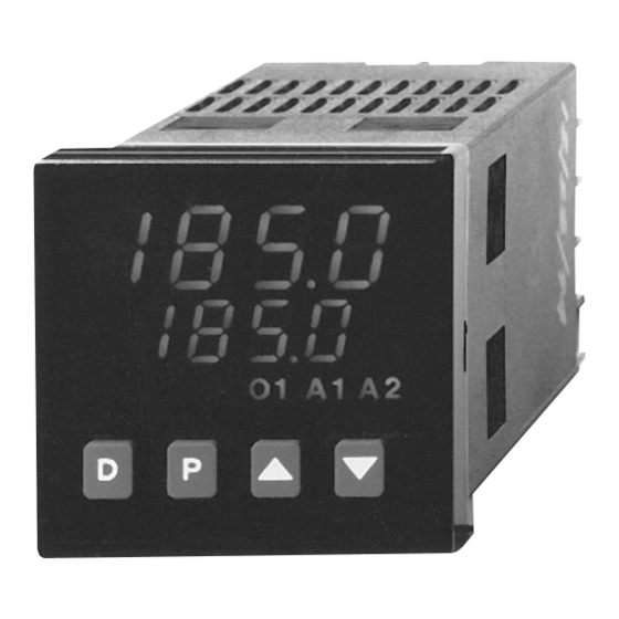
Omega CN63100 Series User Manual (92 pages)
1/16 DIN Temperature/Process Controllers
Brand:
Omega
| Category:
Temperature Controller
| Size: 1.5 MB
Table of Contents
Table of Contents
3
General Description
9
Safety Summary
9
Installation Description
10
Instructions
10
Multiple Unit Stacking
11
Unit Removal Procedure
11
Removing Bezel Assembly
11
Installing Bezel Assembly
11
Connection Description
12
EMC Installation Guidelines
12
Wiring Connections
13
Signal Wiring
13
Thermocouple (CN63100)
13
Rtd (Cn63100)
13
Signal (CN63300)
14
Power Wiring
14
Control and Alarm Outputs
14
Relay Connections
14
Logic/Ssr Connections (CN63100 Only)
15
Remote Setpoint Wiring
15
Main Linear DC Output Wiring
15
Second Linear DC Output Wiring
15
User Input Wiring
15
Rear Terminal Assignments
16
CN63100 Models Without RS-485 and Analog Output
16
CN63100 Models with RS-485 or Linear DC Analog Output
16
ALL CN63300 Models
17
Serial Connections to a Host Terminal
18
Linear DC Analog Output Jumper Selection
19
Front Panel Description
20
Button Functions
20
Initial Configuration Start-Up
21
Controller Power-Up
21
Parameter Configuration Overview
21
Parameter Configuration Basic Start-Up
21
Parameter Configuration for Serial Start-Up
21
Control Start-Up
21
Valid Control Mode Combinations
22
Front Panel Programming Chart for CN63100 & CN63300 Controllers
23
Normal Display Mode
24
Front Panel Program Disable
24
Unprotected Parameter Mode
25
Protected Parameter Mode
26
Hidden Function Mode
27
Configuration Parameter Mode
27
Reference Tables: Configuration Parameter Modules
28
Configure Module 1 - Input Parameters (1-IN) CN63100
28
Configure Module 1 - Input Parameters (1-IN) CN63300
29
Configure Module 2 - Output Parameters (2-OP)
30
Configure Module 3 - Lockout Parameters (3-LC)
31
Configure Module 4 - Alarm Parameters (4-AL)
32
Configure Module 5 - Cooling Parameters (5-O2)
33
Configure Module 6 - Serial Communications (6-SC)
34
Configure Module 7 - Remote Setpoint Parameters (7-Rs or 7-N2)
35
Configure Module 8 - Second Linear DC Analog Output (8-A2)
35
Configure Module 9 - Factory Service Operations (9-FS)
35
User Parameter Value Chart
36
Configuration Parameter Explanations
38
Input Parameter Module (1- IN) CN63100 Models
38
Input Type (Type)
38
Temperature Scale (SCAL)
38
Temperature Resolution (Dcpt)
38
Digital Input Filtering and Display Update Rate (Fltr)
38
Input Sensor Correction Constant (Shft)
38
Setpoint Limit Values (SPLO & SPHI)
38
Setpoint Ramp Rate (Sprp)
39
User Input (Inpt)
39
Input Parameter Module (1- In) CN63300 Models
40
Input Type (Type)
40
Decimal Point Position (Dcpt)
40
Rounding Increment ( Rnd)
40
Digital Input Filtering and Display Update Rate (Fltr)
40
Scaling Points
40
Display Values (Dsp1 & Dsp2)
41
Signal Input Values (INP1 & INP2)
41
Setpoint Limit Values (SPLO & SPHI)
41
Setpoint Ramp Rate (Sprp)
41
User Input (Inpt)
42
Output Parameter Module (2-OP)
43
Time Proportioning Cycle Time (Cyct)
43
Output Control Action (OPAC)
43
Output Power Limits (OPLO & OPHI)
43
Sensor Fail Power Level (OPFL) CN63100 Only
43
Output Power Dampening Filtering Time (Opdp)
43
ON/OFF Control Hysteresis (CHYS)
44
Auto-Tune Code (Tcod)
44
Main Linear DC Output Range (Antp) (Optional)
44
Main Linear DC Output Source (ANAS) (Optional)
44
Main Linear DC Update Time (Anut) (Optional)
44
Main Linear DC Output Scaling Points (ANLO, Anhl) (Optional)
44
Lockouts Parameter Module (3-LC)
45
Lower Display Lockouts (SP, OP, Dev, Udsp and Bdsp)
45
Protected Mode Lockouts (Code, Pid, and AL)
45
Hidden Mode Lockouts (Alrs, SPSL, Trnf, and Tune )
45
Alarm Parameter Module (4-AL) (Optional)
46
Alarm Action (Act1, Act2)
46
Alarm Action Figures
47
Alarm Reset (Rst1, Rst2)
49
Alarm Standby Delay (Stb1, Stb2)
49
Alarm Value (AL-1, AL-2)
49
Alarm Hysteresis (AHYS)
49
Cooling Parameters Module (5-02) (Optional)
50
Cooling Output Cycle Time (CYC2)
50
Cooling Relative Gain (Gan2)
50
Heat and Cool Overlap/Deadband (Db-2)
50
Serial Communications Module (6-SC) (Optional)
51
Baud Rate (Baud)
51
Character Frame Format (Conf)
51
Controller Address Number (Addr)
51
Abbreviated or Full Transmission (Abrv)
51
Print Options (Popt)
51
Remote Setpoint Parameters Module (7-N2 or 7-Rs) (Optional)
52
Remote Setpoint Display Values (Dsp1 and Dsp2)
52
Remote Setpoint Signal Input Values (INP1 and INP2)
52
Remote Setpoint Filtering (Fltr and Band)
52
Remote/Local Setpoint Transfer Options (Trnf)
52
Second Linear DC Analog Output Module (8-A2) (Optional)
53
Second Linear DC Output Range (A2Tp)
53
Second Linear DC Output Scaling Points (A2LO, A2Hl)
53
Factory Service Operations Module (9-FS)
53
Manual Control
54
On/Off Control
55
Auto-Tune for Pid Control
58
Initiate Auto-Tune
59
Auto-Tune of Heat/Cool Systems
59
Auto-Tune of Cascade Control
59
Pid Control Explanations
60
Proportional Band
60
Integral Time
60
Derivative Time
61
Output Power Offset (Manual Reset)
61
PID Adjustments
61
Manual Tuning for Pid Control
63
Remote Setpoint Option
64
Cascade Control
64
Serial Communications Interface
65
RS-485 Serial Communications
65
Controller Configuration
65
Sending Commands and Data
65
Sending Numeric Data
65
Controller (Node) Address
65
Commands Table
65
Register Identification Table
66
Terminator Table
66
Examples of Command Strings
66
Command Code Explanations
66
Controller (Node) Address: N
66
Read Register Command Code: T
67
Write Register Command Code: V
67
Reset Alarm Command Code: R
67
Control Action Command Code: C
67
Block Read Register Command Code: P
67
Terminator : * or
67
Block Read Command Byte Table
68
Unique Register Explanations
69
Setpoint Ramp Using Automatic Setpoint Ramping Register: K
69
Setpoint Ramp Using Periodic Setpoint Write Register: B
69
Periodic Setpoint Write Commands
69
PROM Precautions)
69
Output Status: W
69
Communication Format
69
Command Response Time
70
Full Field Controller Transmission Byte Format
71
Abbreviated Controller Transmission Byte Format
72
Troubleshooting Serial Communications
72
Application Examples
73
CN63100 OEM Paint Sprayer Application
73
CN63300 Water Processing Application
74
Checks and Calibration
75
Main Input Check
75
MV Reading Check (CN63100)
75
Thermocouple Cold Junction Temperature Check (CN63100)
75
RTD Ohms Reading Check (CN63100)
75
Voltage Check (CN63300)
75
Current Check (CN63300)
75
Remote Setpoint Input Check (CN63100 and CN63300)
75
Error Flag E-CL
75
Calibration for CN63100
76
Factory Service Operations - Calibration (9-FS)
76
Millivolt Calibration (CAL)
76
Thermocouple Cold Junction Calibration (CJC)
77
RTD Ohms Calibration (Rtd)
77
Main or Second Linear DC Analog Output Calibration
77
Remote Setpoint Calibration
77
Calibration for CN63300
78
Factory Service Operations (9-FS)
78
Input Calibration
78
Main or Second Linear DC Analog Output Calibration
78
Remote Setpoint Calibration
78
Troubleshooting
79
Replaceable Output Board Description
81
Specifications and Dimensions
82
Cn63100 Temperature Controller Part Numbers
86
Cn63300 Process Controller Part Numbers
87
Advertisement
Advertisement
Related Products
Omega CN63300 Series
Omega CN616TC1
Omega CN616TC2
Omega CNi8-AL
Omega CNi8D-AL
Omega CNi16D-AL
Omega CN9121A
Omega CN9210A
Omega CN9212A
Omega CN9110AT
Omega Categories
Measuring Instruments
Thermometer
Oven
Watch
Cooktop
More Omega Manuals
Login
Sign In
OR
Sign in with Facebook
Sign in with Google
Upload manual
Upload from disk
Upload from URL