Sign In
Upload
Manuals
Brands
Mitsubishi Manuals
Controller
A1SH
Mitsubishi A1SH Manuals
Manuals and User Guides for Mitsubishi A1SH. We have
2
Mitsubishi A1SH manuals available for free PDF download: User Manual
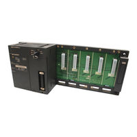
Mitsubishi A1SH User Manual (234 pages)
Brand:
Mitsubishi
| Category:
Controller
| Size: 4.86 MB
Table of Contents
Table of Contents
12
1 Overview
18
Features
19
2 System Configuration
22
Overall Configuration
22
Overall Configuration of Anshcpu
22
Overall Configuration of A1SJHCPU(S8)
24
Precautions When Configuring the System
26
Hardware
26
Software Package
30
System Equipment
32
System Configuration Overview
47
3 Specifications
52
4 Cpu Module
53
Performance Specifications
53
Overview of Operation Processing
56
Operation Processing of RUN, STOP and PAUSE
59
Operation Processing Upon Instantaneous Power Failure
61
Self-Diagnostics Function
62
Device List
65
Parameter Setting Ranges
67
List of Parameter Setting Range
67
Memory Capacity Setting (for Main Program, File Register, Comment, Etc.)
69
Function List
71
Handling Precautions
73
Part Names
74
Parts Names of the A1SHCPU, A2SHCPU(S1), A1SJHCPU (S8)
74
Setting of I/O Control Mode Switching Switch
78
Settings for Memory Write Protect Switch
79
Latch Clear Operation
81
5 Power Supply Module
82
Specifications
82
Power Supply Module Selection
85
Part Names
86
6 Base Unit and Extension Cable
88
Specifications
88
Base Unit Specifications
88
Extension Cable Specifications
89
Application Standards of Extension Base Units (A1S52B(S1), A1S55B(S1), A1S58B(S1), A52B, A55B, A58B)
90
Part Names
94
Installation and Removal of DIN Rail
96
7 Memory Cassette and Battery
98
Memory Cassette
98
Specifications
98
Handling Precautions
99
Installation and Removal of Memory Cassette
100
Writing a Sequence Program to a Memory Cassette
102
Memory Protection Setting of A2SNMCA-30KE
103
Battery
104
Specifications
104
Handling Precautions
104
Battery Installation
105
8 Loading and Installation
106
Fail-Safe Circuit Concept
106
Installation Environment
111
Calculation Method of Heat Amount Generated by the PLC
112
Installing the Base Units
114
Precautions When Installing Programmable Controller
114
Installation
115
Installation and Removal of the Base Units
116
Installation and Removal of the Dustproof Cover
119
Wiring
121
Wiring Instructions
121
Wiring to Module Terminals
126
Precautions When Connecting the Uninterruptible Power Supply (UPS)
128
9 Emc and Low Voltage Directives
129
Requirements for Compliance with EMC Directives
129
EMC Standards
129
Installation Instructions for EMC Directive
130
Cables
131
Power Supply Module
136
Ferrite Core
136
Noise Filter (Power Supply Line Filter)
137
Power Line for External Power Supply Terminal
137
Requirements for Compliance with Low Voltage Directives
138
Standard Applied for MELSEC-Ans Series Programmable Controller
138
Precautions When Using the MELSEC-Ans Series Programmable Controller
138
Power Supply
139
Control Panel
140
Module Installation
141
Grounding
141
External Wiring
141
10 Maintenance and Inspection
142
Daily Inspection
143
Periodic Inspection
144
Battery Replacement
145
Battery Life
145
Battery Replacement Procedure
149
11 Troubleshooting
150
Fundamentals of Troubleshooting
150
Troubleshooting Procedure
151
Flow for Actions When the "POWER" LED Is Turned off
152
Flow for Actions When the "RUN" LED Is Turned off
153
Flow for Actions When the "RUN" LED Is Flickering
154
Flow for Actions When the "ERROR" LED Is Turned on
155
Flow for Actions When the "ERROR" LED Is Flickering
156
Flow for Actions When the Output Module's Output Load Does Not Turn on
157
Flow for Actions When the Program Cannot be Written
158
Flow for Actions When the CPU Module Is Not Started up
159
Error Code List
160
Procedure to Read an Error Code
160
Anshcpu Error Code List
161
Fault Examples with I/O Modules
166
Faults with the Input Circuit and the Corrective Actions
166
Faults in the Output Circuit
168
Appendix
172
Appendix 1 Instruction List
172
Appendix 1.1 Precautions for Write During RUN of a Dedicated Instruction
178
Appendix 2 LISTS of SPECIAL RELAYS and SPECIAL REGISTERS
179
Appendix 2.1 List of Special Relays
179
Appendix 2.2 Special Registers
191
Appendix 3 Precautions When Replacing Anscpu with Anshcpu
210
Appendix 3.1 Differences between A1SHCPU and A1SCPU
210
Appendix 3.2 Differences between A2SHCPU(S1) and A2SCPU
211
Appendix 3.3 Replacement Precautions
211
Appendix 3.3.1 PLC Type Setting
211
Appendix 3.3.2 Precautions When Performing ROM Partition
211
Appendix 3.3.3 Precautions When Utilizing Sequence Programs
212
Appendix 3.3.4 Checking the Influence of the Increased Instruction Processing Speed on the System
212
Appendix 3.3.5 Handling Conventional Memory Cassettes
213
Appendix 3.3.6 Replacing the A2SMCA-14KP (When A2SCPU + A2SMCA-14KP Has Been Used)
213
Appendix 3.3.7 Restrictions on Microcomputer Programs
213
Appendix 4 External Dimensions
214
Appendix 4.1 CPU Module
214
Appendix 4.1.1 A1SHCPU, A2SHCPU(S1) Module
214
Appendix 4.1.2 A1SJHCPU Module
214
Appendix 4.1.3 A1SJHCPU-S8 Module
215
Appendix 4.2 A1S61PN, A1S62PN and A1S63P Power Supply Modules
216
Appendix 4.3 Main Base Unit
217
Appendix 4.3.1 A1S32B Main Base Unit
217
Appendix 4.3.2 A1S33B Main Base Unit
217
Appendix 4.3.3 A1S35B Main Base Unit
218
Appendix 4.3.4 A1S38B Main Base Unit
218
Appendix 4.4 Extension Base Unit
219
Appendix 4.4.1 A1S65B Extension Base Unit
219
Appendix 4.4.2 A1S68B Extension Base Unit
219
Appendix 4.4.3 A1S52B Extension Base Unit
220
Appendix 4.4.4 A1S55B Extension Base Unit
220
Appendix 4.4.5 A1S58B Extension Base Unit
221
Appendix 4.4.6 A1S65B-S1 Extension Base Unit
221
Appendix 4.4.7 A1S68B-S1 Extension Base Unit
222
Appendix 4.4.8 A1S52B-S1 Extension Base Unit
222
Appendix 4.4.9 A1S55B-S1 Extension Base Unit
223
Appendix 4.4.10A1S58B-S1 Extension Base Unit
223
Appendix 4.5 Memory Cassette
224
Appendix 4.5.1 Ansnmca-[ ] Memory Cassette
224
Appendix 4.6 Memory Write Adapter
224
Appendix 4.6.1 A6WA-28P Memory Write Adapter
224
Appendix5 Transportation Precautions
225
Appendix5.1 Relevant Models
225
Appendix5.2 Transportation Guidelines
226
Appendix6 Handling of Batteries and Devices with Built-In Batteries in EU Countries
227
Appendix6.1 Disposal Precautions
227
Appendix6.2 Exportation Precautions
228
Advertisement
Mitsubishi A1SH User Manual (186 pages)
Brand:
Mitsubishi
| Category:
Controller
| Size: 2.34 MB
Table of Contents
Table of Contents
10
Overview
16
Features
17
System Configuration
18
Overall Configuration
19
Total Configuration of Anshcpu
19
Total Configuration of A1SJHCPU(S8)
21
Cautions on Configuring a System
23
Hardware
23
Software Packages
26
System Equipment
28
General Description of System Configuration
38
Outline of Anshcpu Configuration
38
Outline of A1SJHCPU(S8) Configuration
39
Specifications
40
Anshcpu MODULE
41
Performance Specifications
41
Outline of Anshcpu Operation Processing
43
Operation Processing in the RUN, STOP, PAUSE Status
45
Operation Processing When a Momentary Power Interruption Occurs
46
Self-Diagnosis
47
List of Devices
49
List of Parameter Setting Ranges
51
Memory Capacity Settings (Main Programs, File Registers, Comments, Etc.)
53
Functions
55
Handling Precautions
56
Part Identification and Setting
57
Part Identification of Anshcpu, A1SJHCPU (S8)
57
I/O Control Switch Setting
60
Memory Write Protect Switch Setting
60
Clearing Latched Data
62
Power Supply Module
63
Specifications
63
Base Unit and Extension Cable
68
Specifications
68
Specifications of Base Units
68
Specifications of Extension Cables
69
Application Standards for Extension Base Units (A1S52B(S1), A1S55B(S1), A1S58B(S1), A52B, A55B, A58B)
69
Installing and Removal On/From a DIN Rail
76
Memory Cassette and Battery
78
Memory Cassette
78
Specifications
78
Handling Precautions
79
Installing and Removing a Memory Cassette
80
Writing a Sequence Program to a Memory Cassette
82
Memory Write-Protect Setting for an A2SNMCA-30KE
83
Battery
84
Specifications
84
Installation of the Battery
84
Loading and Installation
85
Consideration for Safety
85
Installation Environment
88
Calculation of Heat Generated by the Programmable Controller System
88
Module Mounting
91
Mounting Instructions
91
Installation
95
Installing and Removing the Dustproof Cover
95
Wiring
97
Wiring Instructions
97
Wiring to Module Terminals
100
Precaution When Connecting the Uninterruptive Power Supply (UPS)
100
Emc Directive and Low-Voltage Instruction
101
Requirements for Compliance to EMC Directive (89/336/EEC)
101
EMC Standards
101
Ferrite Core
107
Noise Filter (Power Supply Line Filter)
107
Requirement to Conform to the Low-Voltage Instruction
108
Standard Applied for Ans Series
108
Precautions When Using the Ans Series
109
Power Supply
109
Control Box
110
Module Installation
110
Grounding
111
External Wiring
111
10. Maintenance and Inspection
112
Daily Inspection
113
Periodic Inspection
114
Replacement of Battery
115
Service Life of Battery
115
Battery Replacement Procedure
116
11. Troubleshooting
117
Basic Troubleshooting
117
11. Troubleshooting
118
Troubleshooting Flowcharts
118
Flowchart Used When the POWER LED Goes off
119
Flowchart Used When the RUN LED Goes off
120
Flowchart Used When the RUN LED Flashes
121
Flowchart Used When the ERROR LED Is Lit
122
Flowchart Used When the ERROR LED Flashes
123
Flowchart Used When the Output Load of the Output Module Does Not Come on
124
Flowchart Used When a Program Cannot be Written to the PLC CPU
125
Error Code List
126
Error Codes
126
I/O Connection Troubleshooting
132
Input Circuit Troubleshooting
132
Output Circuit Failures and Corrective Action
134
Appendices
135
Appendix 1 Instructions
135
Appendix 1.1 Caution When Performing a Write While Running Dedicated Instruction
139
Appendix 2 Special Relay, Special Register List
140
Appendix 2.1 Special Relay List
140
Appendix 2.2 Special Registers D
152
Appendix 3 Precautions When Switching from Anscpu to Anshcpu
170
Appendix 3.1 Dissimilarities between A1SHCPU and A1SCPU
170
Appendix 3.2 Dissimilarities between A2SHCPU(-S1) and A2SCPU
171
Appendix 3.3 Precautions When Switching the Model
171
Appendix 3.3.1 PLC Type Setting
171
Appendix 3.3.2 the Precaution When Performing the ROM Cutoff
171
Appendix 3.3.3 the Precaution When Utilizing the Sequence Program
172
Appendix 3.3.4 System Comfirmation by High-Speed Instruction Processing
172
Appendix 3.3.5 Handling Conventional Memory Cassettes
172
Appendix 3.3.6 Switching from the A2SMCA-14KP (When A2SCPU + A2SMCA-14KP Has Been Used)
173
Appendix 3.3.7 Restrictions in Microcomputer Programs
173
Appendix 3.3.6
173
Outside Dimensions
174
Appendix 4.1 CPU Module
174
Appendix 4.1.1 A1SHCPU/A2SHCPU(S1) Module
174
Appendix 4.1.2 A1SJHCPU Module
174
Appendix 4.3 Main Base Units
176
Appendix 4.3.1 A1S32B Main Base Unit
176
Appendix 4.3.2 A1S33B Main Base Unit
176
Appendix 4.3.3 A1S35B Main Base Unit
176
Appendix 4.4 Extension Base Units
178
Appendix 4.4.1 A1S65B Extension Base Unit
178
Appendix 4.4.2 A1S68B Extension Base Unit
178
Appendix 4.4.10 A1S58B-S1 Extension Base Unit
182
Appendix 4.5 Memory Cassette
183
Appendix 4.5.1 Ansmca-[ ] Memory Cassette
183
Appendix 4.5.2 Ansnmca-[ ] Memory Cassette
183
Appendix 4.6 Memory Write Adapter
184
Appendix 4.6.1 A6WA-28P Memory Write Adapter
184
Appendix 4.6
184
Transportation Precautions
184
Appendix 5.1 Controlled Models
184
Appendix 5.2 Transport Guidelines
184
Advertisement
Related Products
Mitsubishi MELSEC A1SH42
Mitsubishi MELSEC-A A1SHCPU
Mitsubishi MELSEC A1S65B
Mitsubishi MELSEC A1S63P
Mitsubishi MELSEC A1SX41-S2
Mitsubishi MELSEC A1SY41
Mitsubishi MELSEC A1SG60
Mitsubishi MELSEC A1SC05NB
Mitsubishi MELSEC QnA A1SJ71QE71N-B5
Mitsubishi MELSEC A1SJ71QC24N1
Mitsubishi Categories
Air Conditioner
Controller
Projector
Automobile
Engine
More Mitsubishi Manuals
Login
Sign In
OR
Sign in with Facebook
Sign in with Google
Upload manual
Upload from disk
Upload from URL