Sign In
Upload
Manuals
Brands
Kerotest Manuals
Control Unit
MODEL-1
Kerotest MODEL-1 Gate Valve Manuals
Manuals and User Guides for Kerotest MODEL-1 Gate Valve. We have
2
Kerotest MODEL-1 Gate Valve manuals available for free PDF download: Operation Manual, Installation, Operation And Maintenance Manual
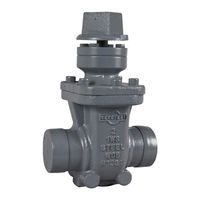
Kerotest MODEL-1 Installation, Operation And Maintenance Manual (30 pages)
GATE VALVE
Brand:
Kerotest
| Category:
Control Unit
| Size: 2 MB
Table of Contents
Table of Contents
1
Scope
3
Product Description and Features
3
Figure 1: Model 1 Pressure-Temperature Chart
3
Cautions and Warnings
4
Valve Identification
4
Valve Components
4
Table 1: Valve Specifications
5
Figure 2: Valve Components
5
Figure 3: Design Changes
5
Accessories
6
Handwheel
6
Locking Device
6
Table 2: Handwheel Options
6
Coating
7
Figure 4: Locking Device
7
Factory Testing
8
Table 3: Minimum Test Parameters
8
Storage, Handling, and Installation
9
Storage
9
Handling
9
Installation
9
General Notes on Installation
9
Screwed End Valves
9
Socket Weld End Valves
10
Flanged End Valves
10
Butt Weld End Valves
11
Butt Weld End X Flange End Valves
11
Figure 5: Bolt Torquing Pattern Examples
11
Operation
12
General Valve Operation
12
Operating Torque
12
Critical Torque
12
Table 4: Valve Torque Values
12
Pressure Drop
13
Repair Service
13
Shut-Off or Seat Leak
13
Clearing Internal Debris
13
Body and Wedge Seating
13
Table 5: Pressure Drop and CV
13
External Stem Packing Leak
14
Packing Shim Installation under Pressure
14
Repacking a Valve with Zero Pressure
15
Table 6: Gland Cap Screw Torque Values
16
Table 7: Packing Repair Part Numbers
16
Table 8: Packing Repair All-Thread Studs
17
Figure 6: Valve Packing Components
17
External Bonnet Seal Leak
18
Sealing a Bonnet Leak with Zero Pressure
18
Sealing a Bonnet Leak under Pressure
18
Table 9: Bolt Replacement Support Clamps
19
Table 10: Bonnet Cap Screw Torque Values
19
Figure 7: Support Clamp Installations
19
Figure 8: Teflon Rope Installation Diagram
20
Figure 9: All-Thread Installation Diagram
20
Table 11: Bonnet Gaskets
21
Table 12: Bonnet Cap Screws
21
Broken Stems
22
Valve Operation with Broken Stem
22
Stem Repair
22
Service Parts Ordering Procedure
23
Table 13: Broken Stem Repair Kit Part Numbers
23
Figure 10: Broken Stem Repair
23
Appendix A: Broken Bolt Removal
24
Information and Background
24
Model-1 Bolt Removal Procedure
24
Figure 11: Bonnet Broken Bolt Diagram
24
Table 14: Bonnet Bolt Removal Chart
25
Table 15: 72631146 Repair Kit Components
25
Appendix B: Bonnet Screw Tightening Procedure
26
Incremental Tightening Procedure
26
Cross-Pattern Tightening Sequences
26
Table 16: Cross-Pattern Tightening Sequences
26
Figure 12: Example Pattern for 12-Bolt Tightening Sequence
27
Appendix C: Model-1 - Nps 1 and 1 ¼ Bolt Replacement Fixture for Field Service Repair
28
Figure 13: Bolt Replacement Instructions (1 of 2)
28
Figure 14: Bolt Replacement Instructions (2 of 2)
29
Advertisement
Kerotest MODEL-1 Operation Manual (48 pages)
Gate valve
Brand:
Kerotest
| Category:
Control Unit
| Size: 0 MB
Table of Contents
Revision Sheet
2
Valve Components
4
Valve Installation
7
Pressure Drop
30
Valve Operation
31
Advertisement
Related Products
Kerotest EV-11
Kerotest WELDBALL
Kerotest Categories
Control Unit
Measuring Instruments
More Kerotest Manuals
Login
Sign In
OR
Sign in with Facebook
Sign in with Google
Upload manual
Upload from disk
Upload from URL