Sign In
Upload
Manuals
Brands
HP Manuals
Inverter
8719A
HP 8719A Manuals
Manuals and User Guides for HP 8719A. We have
2
HP 8719A manuals available for free PDF download: Service Manual, Operating And Service Manual
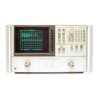
HP 8719A Service Manual (275 pages)
MICROWAVE NETWORK ANALYZER
Brand:
HP
| Category:
Measuring Instruments
| Size: 10.37 MB
Table of Contents
Table of Contents
6
Service and Equipment Overview
11
Introduction
11
Organization of the Service Manual
11
Table of Service Test Equipment
13
Preventive Maintenance
15
Introduction
15
Check the Front Panel Connectors
15
Check the Error Terms
15
Perform a Full 2-Port Calibration
16
Plot the Error Terms
16
Clean the Fan Filter
17
Clean the Glass Filter
18
Verification
19
Operators Check
19
Procedure
20
Equipment
20
In Case of Difficulty
21
System Verification
23
Description
23
Verification Kit
23
System Verification Cycle and
23
Measurement Uncertainty
24
Equipment
24
System Verification
24
Connecting Devices
29
In Case of Failure
30
Connecting the Airlines
31
Calibration Cycle
41
If the Instrument Fails a Test
41
Frequency Range and Accuracy
42
Performance Test
42
Equipment
42
Description and Procedure
42
If the Instrument Fails this Test
42
Power Level Performance Test
43
Equipment
43
Description and Procedure
43
If the Instrument Fails this Test
44
Dynamic Range Performance Test
45
Equipment
45
Description and Procedure
45
If the Instrument Fails this Test
45
Option 003 Performance Test Record
45
Performance Test Record
46
Adjustments
48
Order of Adjustments
48
Test Equipment
49
Instrument Cover Removal
49
A9 CC (Correction Constant) Jumper Position
49
A9 CC Jumper Position Procedure
50
Focus Adjustments
51
Equipment
51
Description and Procedure
51
HP 8719A/20B Display Lntensity
53
Adjustments
54
Description and Procedure
56
Serial Number Correction Constant
57
Description and Procedure
57
Option Numbers Correction Constant
58
Description and Procedure
58
Analog Bus Correction Constants
60
Description and Procedure
60
IF Amplifier Correction Constants
60
Equipment
60
ADJUSTMENTS (Cont'D)
61
ADC Linearity Correction Constants
61
Equipment
61
Description and Procedure
61
Source Pretune Correction Constants
62
Equipment
62
Description and Procedure
62
EEPROM Backup Disk Procedure
63
Equipment
63
Description and Procedure
63
How to Make an EEPROM Backup
63
Data to It
63
The EEPROM Backup Disk
64
HP 8720A Display Image Size. Position and Trace Alignment Adjustments
65
Description and Procedure
65
Reference Assembly VCO Tune Adjustment
66
Description and Procedure
66
Frequency Accuracy Adjustment
67
Equipment
67
Description and Procedure
67
Sampler Check
68
Description and Procedure
68
A Sampler Check
68
B Sampler Check
68
R Sampler Check
69
Power Adjustments
70
Equipment
70
Low Band Power Level Adjustment
70
Description and Procedure
70
Automatic Leveling Control Adjustment
73
Description and Procedure
73
Optional Fractional-N Spur and
74
FM Sideband Adjustment
74
Description and Procedure
75
Cal Kit Defaults Correction Constants
76
Description Ande Procedure
76
Introduction
79
Troubleshooting HP-IB Systems
80
Controllers
80
Isolate Faulty Group
84
Introduction
84
Power Supply
84
Digital Control
85
Source
85
Receiver
86
Accessories
86
Isolate Faulty Group Worksheets
88
Power Supply
90
Introduction
90
LED State Definitions
90
Start here
92
Fan
92
Power Supply Error Messages
92
Check A15 Preregulator and Loads
92
Check A15 Green LED on Rear Panel
92
Check A15 and +5V Loads
93
Remove A51 Loads
94
Check A8 Post-Regulator and Loads
95
Checkfan Display
96
Check Assemblies Loading
96
Supply
96
A8 Leds Are Not All on
96
Check A8 Alone
97
Check Upper Box Assemblies
97
Check Lower Box Assemblies
97
Check the Display
97
Measure A8 Fan Voltages
98
Measure A15 Fan Voltages
98
Display Power Troubleshooting
99
Verify A8 Display Voltages
99
Test Point Voltages
101
In Case of Difficulty
102
Introduction
103
Digital Control
103
Start here
103
Abus Test Failure
103
Fatal Errors
103
HP-IB Failures
103
Preliminary Checks (All Models)
104
Display Check (All Models)
104
DIGITAL CONTROL (Cont'D)
106
Diagnostic Checks
106
Front Panel Control Check (All Models)
106
Fatal Error Troubleshooting
108
Display Troubleshooting (All Models)
108
HP 8719A/20B Display Troubleshooting
108
Measure Display Power Supply Voltages Entering A19
108
Display Power Supply Troubleshooting
109
Run Display Test 52
109
Inspect Ribbon Cable and Repeat Display Test 52
109
Perform Walking One Pattern
110
Run Remaining Display Tests
110
HP 8720A Display Troubleshooting
111
Check Display Power Supplies
111
Check Display Test Pattern
113
Check Display Intensity and Focus
113
Identify the Faulty Assembly
116
HP-IB Troubleshooting
116
No Front Panel Control
116
Stuckkey
117
Source
119
Start here
119
Phase Lock Error Message Displayed
119
Source Troubleshooting Flowchart
120
Power Not Within Specifications
121
Broadband Phase Lock Problems
121
Check A7 ALC by Disconnecting W2
122
Swap Samplers to Check A64 R Sampler
122
Check Open Loop Power
122
Check A12 Reference
123
Check A14 Fractional-N
123
A14 VCO Range Check with Oscilloscope
124
A14 VCO Exercise
125
A14 Divide-By-N Circuit Check
126
A14-To-A13 Digital Control Signals Check
126
A52 Pulse Generator Check
127
Broadband Power Problems
131
A7 Alcisignal Separation Check
131
A69 Step Attenuator Check
131
HP 8719 and HP 8720
131
A67 Power Splitter Check
132
Measuring Lower Box Bias Voltages
132
Receiver
134
Introduction
134
Start here
134
All Signal Paths Look Bad
135
2Nd lo Check
135
Mhz Check
135
At Least One Signal Path Looks Good
135
Directional Coupler Check
136
A and B Sampler Check by Substitution
137
Sampler Voltage Check
137
2Nd Converter Check
137
Accessories
139
Introduction
139
Start here
139
Inspectandgageconnectors
140
Switch Repeatability
140
Inspect Error Terms
141
Isolate the Fault in the RF Path
142
Cable Test
143
Verify Shorts and Opens
144
Service Key Menus
146
Introduction
146
Internal Diagnostics Summary
146
Tests Menu
147
Test Options Menu
148
Self Diagnose Softkey
149
Test Descriptions
149
Internal Tests
149
External Tests
151
Sys Ver Tests
151
Adjustment Tests
152
Display Tests (HP 8719A120B)
152
Test Patterns
153
Service Modes Summary
154
Service Modes more Menu
156
SRC Tune Menu
156
SERVICE KEY MENUS (Cont'D)
157
ALC on off Softkey
157
Peekipoke Menu
157
Firmware Revision Softkey
158
Input Ports Menu
158
Analog Bus Menu
159
Description of the Analog Bus
159
The Frequency Counter
160
Notes
160
Analog Bus Nodes
160
A10 Digital if
161
A L L Phase Lock
164
A12 Reference
164
A14 Fractional-N (Digital)
165
Invoking Tests Remotely
166
Symbol Conventions
166
Analog Bus Codes
167
Error Terms
169
Error Term Inspection
171
Hardcopy Procedure
172
Error Term Descriptions
172
Directivity (EDF and EDR)
173
Source Match (ESF and ESR)
174
Reflection Tracking (ERF and ERR)
175
Isolation (Crosstalk. EXF and EXR)
176
Load Match (ELF and ELR)
177
Transmission Tracking (ETF and ETR)
178
Introduction
179
Theory of Operation
179
System Operation
179
Functional Groups of the Analyzer
180
Power Supply Theory
181
A15 Preregulator
181
A8 Post-Regulator
182
Digital Control Theory
184
A1 Front Panel
185
A2 Front Panel Processor
185
A9 Cpu
185
A18 Display
186
A16 Rear Panel
186
Source Group Theory
187
Source Pretune
188
A14/A13 Fractional-N Synthesizer
188
Harmonic Comb
188
Phase Locked Sweep
189
A12 Reference: the Crystal Reference Frequencies
189
Signals
190
A7 ALC: Automatic Leveling Control
191
Signal Separation
193
A67 Power Splitter. A68 Attenuator
193
A69 Step Attenuator
193
S4 Transfer Switch
194
A56 Lower Front Panel Assembly
194
A60 and A61 DC Bias Tees
194
A62 and A63 Directional Couplers
194
Receiver Theory
195
Samplers and Second Converters
195
A10 Digital if
196
Replaceable Parts
197
Introduction
197
Replaceable Parts Figures
197
Adjustments and Verification
197
(R-E) Rebuilt-Exchange Assemblies Cost Less
197
Ordering Information
198
How to Order Parts Fast
198
Introduction
231
Replacement Procedures
231
Adjustments and Performance Tests
231
Cover Removal
231
Tools Required
233
Procedure
233
To Disassemble
233
To Remove the Rotary Pulse
233
A18 Display Replacement
235
To Disassemble
235
To Remove the A16 Rear Panel Assembly
240
To Remove the Preregulator
240
To Reassemble
240
A64/A65/A66 Sampler Replacement
242
Tools Required
242
Procedure
242
To Disassemble
242
To Remove the a or B Sampler
242
To Remove the R Sampler
242
To Reassemble
245
A62/A63 Directional Couplers
246
Tools Required
246
Procedure
246
To Remove the Front Panel Board
246
A60/A61 Bias Tees and S4 Transfer Switch Replacement
250
Tools Required
250
To Remove the Bias Tees
250
To Remove the Transfer Switch
250
To Reassemble
250
A69 Step Attenuator Replacement
251
Tools
251
Procedure
251
To Disassemble
251
To Reassemble
251
A51 Interface Replacement
252
Tools Required
252
Procedure
252
To Disassemble
252
To Reassemble
254
A53 Mixer/Amplifier Replacement
257
Tools Required
257
Procedure
257
To Disassemble
257
To Reassemble
257
A55 YIG 1/A54 YIG 2 Replacement
259
Tools Required
259
Procedure
259
To Disassemble
259
To Reassemble
259
S1/S2/S3 Microwave Switch Replacement
260
Tools Required
260
Procedure
260
To Disassemble
260
To Reassemble
260
Introduction
262
Instrument History
265
Introduction
265
Index
269
Advertisement
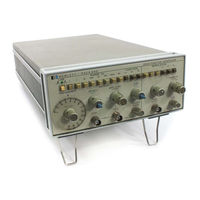
HP 8719A Operating And Service Manual (69 pages)
Function generator
Brand:
HP
| Category:
Inverter
| Size: 3.95 MB
Table of Contents
Warranty
3
Safety Information
3
Safety Symbols
3
Table of Contents
6
List of Tables
7
List of Illustrations
7
Safety Summary
8
Sweep Output. Output Level
10
Burst. Symmetry. Specifications
10
Instrument and Manual Identification
10
Specifications
11
General Information Table
11
Installation
12
Power Requirements. Grounding Requirements
12
Instrument Mounting. Repackaging for Shipment
12
Power Plugs Diagram
12
Operating Instructions
13
Controls and Indicators
13
General Operating Information
13
Generator Outputs
13
Front Panel Diagram
14
Rear Panel Diagram
15
Input Constraints
15
Mudulation Generator Input/Output
15
Output Characteristics
15
Sine Wave Output. Square Wave Output. Triangle Output
16
Ramp. Pulse. Gate or Burst. am
16
Phase Control of Burst Diagram
16
Percent Modulation Diagram
16
Basic Operating Procedures
17
Instrument Turn-On. Fuse Replacement
17
FM. SWP. External Control
17
Frequency. Amplitude
17
Main Generator Operation. Burst
18
Vco
18
Modulation Generator Operation
18
AM Operation Diagram
18
FM Operation Diagram
19
Sweep Operation Diagram
19
Burst Operation Diagram
20
Theory of Operation
21
Basic Block Diagram Description
21
Functional Block Diagram Description
22
Main Generator Section
22
Calibrated Symmetry Diagram
22
Variable Symmetry Diagram
22
Output Section
23
Modulation Generator
23
Level Shifter Diagram
23
Signal Generator Diagram
24
U403 Burst Amplifier Array Diagram
25
Burst Time Relation Waveforms Diagram
25
Required Test Equipment
27
Maintenance
28
Performance Tests
28
Dial Accuracy Test Table
28
Aberration Test
29
Triangle Linearity Test
29
Rise Time Test
29
Triangle Linearity (Positive Slope) Table
30
Triangle Linearity (Negative Slope) Table
30
Sweep Ramp Linearity Test
31
Linearity Table
32
Sine Wave Distortion Test
32
Output Impedance Test
33
Attenuator Accuracy Test
33
Sine Wave Level Flatness Test
33
Amplitude Flatness Diagram
33
Sync Output Impedance and Amplitude Test
34
Sync Output Rise and Fall Time Test. DC Offset Test
34
Internal Modulation Source Output Level Test
34
Internal Modulation Source Spectral Purity Test
34
Variable Symmetry Test
35
Carrier Envelope Distortion Test
35
External Amplitude Modulation Sensivitity Test
35
FM Distortion Test
35
Carrier 3 Db Bandwidth Test (Amplitude Modulation)
36
Frequency Deviation Test
36
FM Distortion Diagram
36
External Frequency Control Input Requirements, VCO Linearity Tests
37
VCO Linearity Graph
37
Adjustment Procedures
38
Power Supply Adjustment
38
Frequency Adjustment
38
Distorstion Adjustment
39
Rise Time and Aberration Adjustment
39
Modulation Symmetry Adjustment
39
Modulation Sinewave Distortion Adjustment
39
Factory Selected Values
40
Factory Selected Components Table
40
Carrier Balance Adjustment
40
Adjustment Locator Diagram
41
Performance Test Card
42
Replaceable Parts
44
Ordering Information
44
Chassis Mounted and Miscellaneous Parts. Non-Listed Parts
44
Standard Abbreviations Table
44
Code List of Manufacturers
45
Replaceable Parts Table
46
Chassis Mounted Components Picture
55
3312A Jack Connections
56
General Schematic Notes
56
Circuit Diagrams
57
Reference Designators
57
Troubleshooting
57
Functional Block Diagram
57
3312A Settings Table
58
Tuning Amplifier Integrator and Ranges Switches Diagram
60
3312A Settings
64
Backdating
66
Advertisement
Related Products
HP 8720B
HP 8752c
HP HP 8642A/B
HP HP 8673D
HP 8569A
HP 8601A
HP 8082a
HP 8340b
Hewlett Packard HP 83650L
HP 8561A
HP Categories
Desktop
Laptop
Server
Monitor
Switch
More HP Manuals
Login
Sign In
OR
Sign in with Facebook
Sign in with Google
Upload manual
Upload from disk
Upload from URL