Sign In
Upload
Manuals
Brands
Honeywell Manuals
Barcode Reader
XL 800 Series
Honeywell XL 800 Series Manuals
Manuals and User Guides for Honeywell XL 800 Series. We have
5
Honeywell XL 800 Series manuals available for free PDF download: User Manual, Operator's Manual, Installation And Commissioning Instructions, Specifications
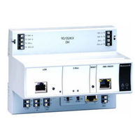
Honeywell XL 800 Series Installation And Commissioning Instructions (36 pages)
Brand:
Honeywell
| Category:
Controller
| Size: 3.17 MB
Table of Contents
Table of Contents
1
General
3
Before Installation
3
Installation
3
Wiring
4
XL800 Series Power Consumption
5
I/O Modules
5
Description of the XCL8010AU Controller Module
7
Overview
7
Earth Ground
9
Interfaces and Bus Connections
10
Technical Data
10
System Data
10
Operational Environment
10
Smoke Control Configuration
10
Data File Set-Up
11
Panel Reset
11
Typical Power Limited Circuit for XL800
11
Connecting Single Bus Controller Systems
11
XCL8010AU, I/O Modules on Single Rail
12
Multiple Rails in Single Cabinet
12
Lonworks Bus I/O Modules in Separate Rooms
12
On Works
12
Connecting I/O Modules
12
Connecting I/O Modules to the XCL8010AU
12
How to Connect Panel Bus and L
12
Setting Address of Panel Bus I/O Modules
13
Setting the I/O Bus Switch
14
Lon Works
14
ON ORKS Bus Topologies
14
C-Bus Topologies
14
Mounting/Dismounting Modules
14
Mounting/Dismounting Controller/Sockets
15
Mounting Sockets
15
Connecting Sockets
15
Dismounting Sockets
16
Mounting/Dismounting Electronic Modules
16
Mounting Electronic Modules
16
Dismounting Electronic Modules
17
Connecting Via C-Bus
17
Connecting to the Controller
17
Setting the C-Bus Termination Switch
17
Shielding
17
Connecting Hmis or Laptops
17
Connecting the XI582 Operator Interface
17
Connecting Laptops (XL-Online/Care)
18
XCL8010AU Terminals
18
Features
18
LON WORKS Interface and Terminals
18
LON WORKS Service LED and Button
18
C-Bus Tx LED and Rx LED
19
Reset Button
19
HMI Interface
19
Alarm and Power Leds
20
Watchdog Status
20
Modem Interface
20
I/O Bus Switch S2
20
C-Bus Termination Switch S1
21
Memory
21
Description of the I/O Modules
21
Common Features
21
Analog Input Modules
22
Types of Analog Input Modules
22
Features
22
Terminals
22
XFL821AU Connection Examples
23
Analog Output Modules
24
Types of Analog Output Modules
24
Features
24
Terminals
24
Technical Data
24
Modules with Manual Overrides
25
XFL822AU Connection Example
25
Synchronization Behavior of Analog Output Module Configured as Floating Output
25
Binary Input Modules
26
Types of Binary Input Modules
26
Features
26
Terminals
26
Technical Data
26
Status Leds
27
XF823AU Connection Examples
27
Relay Output Modules
28
Types of Relay Output Modules
28
Features
28
Terminals
28
Permissible Loads
29
Status Leds with Manual Overrides
29
Connection Examples
30
General
31
Troubleshooting
31
Testing Wiring Connections
31
Troubleshooting on the XCL8010AU Controller
31
Power LED (Green)
31
Alarm LED (Red)
32
LON WORKS Service LONED
32
On Orks
32
C-Bus Tx and Rx Leds
33
HMI Tx and Rx Leds
33
I/O Modules Troubleshooting
34
Power LED of I/O Modules
34
Service LED of I/O Modules
35
Advertisement
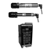
Honeywell XL 800 Series User Manual (41 pages)
Signal Processor and Viewing Head
Brand:
Honeywell
| Category:
Signal Processors
| Size: 3.1 MB
Table of Contents
Table of Contents
1
Application
1
Features
1
Available Viewing Head Models and Associated Features
2
Specifications
3
Signal Processor Mounting
3
Approvals
3
Installation
3
Grounding and Shielding
4
Signal Processor Power Connections
4
Model 700ACSP Signal Processor Wiring
5
Model 700DCSP Signal Processor Wiring
6
Terminal Descriptions
7
Model 700 Viewing Head Cable with 1/2 In. NPT Fitting
7
Viewing Head Connector and Wiring
7
Cable Preparation
8
Model 700/800 Viewing Head Cable Connections
8
Protecting the Viewing Head Cable
9
Viewing Head Connector LED Indicators
9
Viewing Head Mounting and Sighting
9
Pressure
9
Viewing Head Mounting/Sighting
10
Accessories
10
Purge Air
10
Temperature
10
IR Detector
11
UV Detector
11
Filter Selection for IR Viewing Head
11
Operation
11
Self-Checking
12
Adjustment of VH Sighting and Gain
12
Orificing
12
Setting the Viewing Head Gain
13
Signal Processor User Interface
13
Manual Setup of Setpoints
13
Push Button Functions
13
Relay on Setpoint
14
Ratio Relay Off/Relay on Setpoint
14
Setting FFRT
14
0/4-20Ma Output Option
14
Automatic Setup of Setpoints
15
Modbus RTU Function Supported
16
Communication Setting
16
Loading Factory Defaults
16
Modbus Communication
16
MODBUS Registers Map
17
Typical Communication Wiring and Recommended Addressing
18
COMMOD Communication Converter Wiring
18
Lockout or Faulty VH Indication
19
Parameter Match Error
19
Troubleshooting
19
Maintenance
19
Models S702 and S706 Viewing Heads
20
Models S802 and S806 Viewing Heads
20
Model 700DCSP Signal Processor
21
Model 700ACSP Signal Processor
22
Mounting Examples
23
Viewing Head Mounting Example
23
IR Viewing Head Location
24
UV Viewing Head Location
24
Opposed Fired Viewing Head Sighting
25
Setting Factory Defaults
26
Auto Setup
27
Manual Flame on Setup
30
Manual Flame off Setup
31
Flame Failure Response Time Setup
32
0-20/4-20Ma Analog Output Setup
33
Viewing Head Gain Setting
34
700ACSP, 700DCSP Product Declaration
35
Definitions
35
Safety Manual: 700 Signal Processor
35
Safety Function of the 700
36
700AC or 700DC Signal Processor Proof Test Interval
36
The Flame Relay
36
Dependence of the PFD AVG on the Proof Test Interval for 700AC
36
Tests
37
Product Decommissioning
37
Equipment
37
700AC or 700DC Signal Processor Proof Test
37
70X and 80X Viewing Head
38
702, 706, 802, and 806 Product Declaration
38
Safety Manual: 70X & 80X Viewing Head
38
Safety Function of the 702, 706, 802, and 806
39
70X and 80X Viewing Head Proof Test Interval
39
Dependence of the PFD on the Proof Test Interval for S706 and S806
39
70X and 80X Viewing Head Proof Test Procedure
40
Setup
40
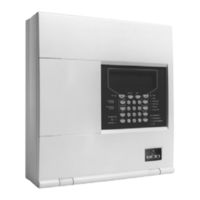
Honeywell XL 800 Series Operator's Manual (44 pages)
Gent Fire Alarm Panel Operator’s Manual & Log book
Brand:
Honeywell
| Category:
Fire Alarms
| Size: 0.75 MB
Table of Contents
Table of Contents
2
I2__04/07
3
General Description
5
User Responsibility
6
Quarterly
7
Battery Replacement
7
Controls and Indicators
8
Navigation
9
Access Levels
9
To Return to Access Level 1
10
Normal Condition
11
Fire Condition
12
To Verify Fire
13
Manual Control of Fire Alarms
14
To Operate Delay Mode
15
Fire Test
16
To Exit Fire Test Mode
17
Fault Condition
18
Disablement Condition
20
Typical Disablement
20
System Information
21
To View Active Disablement
22
To View Historic Events
22
System Set up
23
Hardware Link
23
To Enable or Disable a Zone
24
To Edit a Zone Label
25
To Put a Zone in and out of Test Mode
26
To View Devices in a Zone
27
To Enable or Disable a Device
28
To Edit a Device Label
29
To Enable or Disable Alarm Sounders
30
To Set up Weekly Reminder of Fire Test
31
To Set up the Initial and Verify Delay
32
Other Controls
33
Loop Status
33
Local Input
33
Loop Map
33
Auxiliary Relay
34
Fire Routing Output
34
Fault Routing Output
34
Maintenance Reminder
34
Appendix
35
Glossary of Terms
35
Controls at the System 800 Panel
37
Indicators at the System 800 Panel
38
Advertisement
Honeywell XL 800 Series User Manual (80 pages)
Signal Processor and Viewing Head
Brand:
Honeywell
| Category:
Signal Processors
| Size: 4.65 MB
Table of Contents
Table of Contents
1
Specifications
2
Approvals
3
Installation
3
Operation
11
Modbus Communication
16
Troubleshooting
19
Maintenance
19
Safety Manual: 700 Signal Processor
35
Safety Manual: S70X & 80X Viewing Head
38
Honeywell XL 800 Series Specifications (2 pages)
Barcode Verifier
Brand:
Honeywell
| Category:
Barcode Reader
| Size: 0.21 MB
Advertisement
Related Products
Honeywell Xenon 1911i
Honeywell Xenon 1910i
Honeywell Xenon 1902 Color
Honeywell Xwnon 1900
Honeywell Xwnon 1902
Honeywell Xenon 1952
Honeywell Granit XP 199 i Series
Honeywell Xenon XP 1950h
Honeywell Xenon XP 195 Series
Honeywell Xenon XP 1950g
Honeywell Categories
Thermostat
Controller
Control Unit
Security Camera
Accessories
More Honeywell Manuals
Login
Sign In
OR
Sign in with Facebook
Sign in with Google
Upload manual
Upload from disk
Upload from URL