Sign In
Upload
Manuals
Brands
Honeywell Manuals
Transmitter
SmartLine ST700
Honeywell SmartLine ST700 Manuals
Manuals and User Guides for Honeywell SmartLine ST700. We have
7
Honeywell SmartLine ST700 manuals available for free PDF download: User Manual, Quick Start Installation Manual, Installation Manual
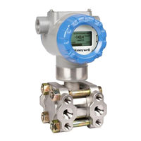
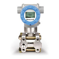
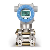
Honeywell SmartLine ST700 User Manual (274 pages)
Pressure Transmitters
Brand:
Honeywell
| Category:
Transmitter
| Size: 5.12 MB
Table of Contents
Table of Contents
7
ST 700 Transmitter Series
17
Overview
17
Table 1 - ST 700 Standard Andf Basic Model Types
18
Introduction to the ST 700 Standard Transmitter
19
Features and Options
19
Table 2 - Features and Options_St 700 Standard Transmitter
19
Physical Characteristics
20
Figure 1 - ST 700 Standard Transmitter Major Assemblies
20
Figure 2 - ST 700 Standard Transmitter Electronics Housing Components
20
Functional Characteristics
21
ST 700 Standard Transmitter Nameplate
21
Figure 3 -ST 700 Standard Transmitter - Typical Name Plate
21
Safety Certification Information
22
Transmitter Adjustments
22
Display Options -Standard Display
22
Table 3 - Available Display Characteristics
22
Optional Integrated Two-Button Assembly (Standard Display)
23
Application Design for the ST 700 Standard Transmitter
24
Overview
24
Accuracy
24
Diagnostic Messages
25
Safety
26
Table 4 - ST 700 Standard Transmitter - Basic Display Diagnostics Messages
26
Safety Integrity Level (SIL)
27
Installation and Startupfor the ST 700 Standard Transmitter
28
Installation Site Evaluation
28
Honeywell MC Toolkit
28
Display Installation Precautions
28
Mounting ST 700 Standard Transmitters
29
Summary
30
Figure 4 - ST 700 Standard Transmitter - Typical Bracket and Flange Mounted Installations
30
Flush Mounting - ST 700 Standard Transmitter
31
Figure 5 - ST 700 Standard Transmitter - Typical Flush Mounted Installation
31
Mounting Dimensions
32
Bracket Mounting Procedure
33
Figure 6 - ST 700 Standard Transmitter - Angle Mounting Bracket Secured to a Horizontal or Vertical
33
Table 5 - ST 700 Standard Transmitter - Mounting Bracket Procedure
33
Figure 7 - ST 700 Standard Transmitter - Inline Model Mounted to an Optional Bracket
34
Figure 8 - ST 700 Standard Transmitter - Rotating the Electronics Housing
34
Mounting Transmitters with Small Absolute or Differential Pressure Spans
35
Figure 9 - ST 700 Standard Transmitter - Using a Spirit Balance to Level a Transmitter
35
Flange Mounting
36
Figure 10 - ST 700 Standard Transmitter - Tank-Flange Mounted Transmitter
36
Remote Diaphragm Seal Mounting Information
37
Figure 11 - ST 700 Standard Transmitter - Representative Remote Diaphragm Seal Transmitter
37
Table 6 - ST 700 Standard Transmitter - Flange Mounting Guidelines
37
Table 7 - ST 700 Standard Transmitter - Remote Diaphragm Mounting Details
37
Piping the ST 700 Standard Transmitter
38
Piping Arrangements
39
Figure 12 - ST 700 Standard Transmitter - Typical 3-Valve Manifold with Blow-Down Piping
39
Transmitter Location
40
Table 8 - ST 700 Standard Transmitter - Suggested Connection Locations
40
General Piping Guidelines
41
Procedure to Install Flange Adapters
42
Wiring the ST 700 Standard Transmitter
42
Figure 13 - ST 700 Standard Transmitter - Flange Adapter Removal and Replacement
42
Overview
43
Figure 14 - ST 700 Standard Transmitter - Operating Ranges
43
Figure 15 - ST 700 Standard Transmitter - 3-Screw Terminal Board and Grounding Screw
44
Digital System Integration Information
46
Wiring Variations
47
Wiring Procedure
48
Lightning Protection
49
Supply Voltage Limiting Requirements
50
Process Sealing
51
Explosion-Proof Conduit Seal
52
Startup - ST 700 Standard Transmitter
53
Overview
54
Startup Tasks
55
Output Check Procedures
56
Constant Current Source Mode Procedure
57
Figure 16 - ST 700 Standard Transmitter - Current Loop Test Connections
57
Operation_St 700 Standard Transmitter
58
Overview
58
Three-Button Operation
58
Figure 17 - ST 700 Standard Transmitter - Three-Button Option
58
Table 9 - Three-Button Option Functions
59
The Basic Display Menu
60
Table 10 - the Basic Display Menus
61
Data Entry
64
Table 11 - Three-Button Data Entry
64
Editing a Numeric Value
65
Selecting a New Setting from a List of Choices
66
Two-Button Operation
67
Figure 18 - ST 700 Standard Transmitter - Two-Button Option
67
The Standard Display Menu
68
Table 12 - ST 700 Basic Transmitter: Standard Display Menus
68
Standard Display Abbreviations
87
Table 14 - ST 700 Basic Transmitter - the Standard Display Abbreviations
87
Data Entry
88
Table 15 -Two-Button Data Entry
88
Editing a Numeric Value
89
Selecting a New Setting from a List of Choices
90
Basic and Standard Display Operations
91
Editing a Numeric Value
92
Selecting a New Setting from a List of Choices
93
Three Button Operation with no Display Installed
94
Zero Adjustment
95
Span Adjustment
96
Changing the Default Failsafe Direction
97
And Analog Differences
98
Procedure to Establish Failsafe Operation
99
Figure 19 - ST 700 Standard Transmitter - Locating the Failsafe and Write Protect Jumpers
99
Table 16 - ST 700 Standard Transmitter - HART and de Failsafe and Write Protect Jumpers
100
Table 17 - ST 700 Standard Transmitter - Fieldbus Simulation and Write Protect Jumpers
101
Monitoring the Basic and Standard Displays for the ST 700 Standard Transmitter
102
Basic Display_St 700 Standard Transmitter
103
Figure 20 - ST 700 Standard Transmitter - Basic Display with Process Variable Format
103
Standard Display_St 700 Standard Transmitter
104
Figure 21 - ST 700 Standard Transmitter - Standard Display with Process Variable Format
105
Maintenance_St 700 Standard Transmitter
106
Overview
106
Preventive Maintenance Practices and Schedules
106
Inspecting and Cleaning Barrier Diaphragms
106
Figure 22 - ST 700 Standard Transmitter - DP Transmitter Head Disassembly
107
Figure 23 - ST 700 Standard Transmitter - Head Bolt Tightening Sequence
108
Table 18 - Head Bolt Torque Values
108
Replacing the Communication Module
109
Figure 24 - ST 700 Standard Transmitter - PWA Replacement
109
Replacing the Meter Body
111
Figure 25 - ST 700 Standard Transmitter - Disassembly for Meter Body Replacement
111
Figure 26 - ST 700 Standard Transmitter - Hardware Location to Remove the Meter Assembly
112
Figure 27 - ST 700 Standard Transmitter - Meter Body Reassembly
113
Figure 28 - ST 700 Standard Transmitter - Head Bolt Tightening Sequence
113
Calibration for the ST 700 Standard Transmitter
115
Recommendations for Transmitter Calibration
115
Calibration Procedures
115
Troubleshooting on the ST 700 Standard Transmitter
116
Overview
116
Critical Diagnostics Screens
116
Fault Conditions and Recommended Corrective Actions - Basic Display
117
Table 19 - ST 700 Standard Transmitter - Fault Conditions and Recommended Corrective Actions for Basic Display
117
Fault Conditions and Recommended Corrective Actions - Standard Display
118
Table 20 - ST 700 Standard Transmitter - Fault Conditions and Recommended Corrective Actions
118
Parts List_St 700 Standard Transmitter
119
Overview
119
Table 21 - ST 700 Standard Transmitter - Summary List of Recommended Spare Parts
119
Figure 29 - ST 700 Standard Transmitter - Angle and Flat Bracket Parts
120
Figure 30 - ST 700 Standard Transmitter - Electronic Housing, Display End
121
Table 22 - ST 700 Standard Transmitter - Angle and Flat Bracket Parts
121
Table 23 - ST 700 Standard Transmitter Major Assemblies
122
Figure 31 - ST 700 Standard Transmitter - Electronic Housing, Terminal Block End
123
Figure 32 - ST 700 Standard Transmitter - Major Assemblies
124
Table 24 - ST 700 Standard Transmitter Models STD720, 730 & 770
125
Figure 33 - ST 700 Standard Transmitter - ST 700 Models STD720, 730, 770
127
Figure 34 - ST 700 Standard Transmitter - STG730, 740, 770 and STA722, 740 Transmitter Body
130
Figure 35 - ST 700 Standard Transmitter - Inline Gauge and Inline Atmospheric Meter Body Bodies
131
Table 26 - ST 700 Standard Transmitter - Inline Gauge and Inline Atmospheric Meter Body Parts
131
Figure 36 - ST 700 Standard Transmitter - Extended Flange Design
132
Figure 37 - ST 700 Standard Transmitter - Flush Flange Design
132
Table 27 - ST 700 Standard Transmitter - Flange-Mounted Meter Body Parts - STF724, 732
132
Figure 38 - ST 700 Standard Transmitter - Pseudo Flange Design
133
Figure 39 - ST 700 Standard Transmitter - Remote Seal Diaphragm
133
Figure 40 - ST 700 Standard Transmitter - Flush Mount Meter Body
134
Table 28 - ST 700 Standard Transmitter - Flush Mount Meter Body Parts
134
Introduction_St 700 Basic Transmitter
135
Overview
135
Features and Options
135
Table 29 - ST 700 Basic Transmitter - Features and Options
135
Physical Characteristics
136
Figure 41 - ST 700 Basic Transmitter - Major Assemblies
136
Figure 42 - ST 700 Basic Transmitter Electronics Housing Components
136
Functional Characteristics
137
ST 700 Transmitter Nameplate
137
Figure 43 - ST 700 Basic Transmitter - Name Plate
137
Safety Certification Information
138
Transmitter Adjustments
138
Display Options -Standard Display
138
Table 30 - ST 700 Basic Transmitter - Available Display Characteristics
138
Optional Integrated Two-Button Assembly (Standard Display)
139
Application Design_St 700 Basic Transmitter
140
Overview
140
Accuracy
140
Diagnostic Messages
141
Safety
141
Safety Integrity Level (SIL)
142
Installation and Startup_St 700 Basic Transmitter
143
Installation Site Evaluation
143
Honeywell MC Toolkit
143
Display Installation Precautions
143
Mounting_St 700 Basic Transmitter
144
Summary
145
Figure 44 - ST 700 Basic Transmitter - Typical Bracket Mounted and Flange Mounted Installations
145
Flush Mounting_St 700 Basic Transmitter
146
Figure 45 - ST 700 Basic Transmitter - Typical Flush Mounted Transmitter Installation
146
Mounting Dimensions, ST 700 Basic Transmitter
147
Bracket Mounting Procedure for ST 700 Basic Transmitter
148
Figure 46 - ST 700 Basic Transmitter - Angle Mounting Bracket Secured to a Horizontal or Vertical
148
Table 31 - ST 700 Basic Transmitter - Mounting Bracket Procedure
148
Figure 47 - ST 700 Basic Transmitter - Inline Model Mounted to an Optional Bracket
149
Figure 48 - ST 700 Basic Transmitter - Rotating the Electronics Housing
149
Mounting Transmitters with Small Absolute or Differential Pressure Spans
150
Figure 49 - ST 700 Basic Transmitter, Using a Spirit Balance to Level a Transmitter
150
Flange Mounting_St 700 Basic Transmitter
151
Figure 50 - ST 700 Basic Transmitter, Tank-Flange Mounted Transmitter
151
Remote Diaphragm Seal Mounting Information_St 700 Basic Transmitter
152
Figure 51 - ST 700 Basic Transmitter - Representative Remote Diaphragm Seal Transmitter
152
Table 32 - ST 700 Basic Transmitter, Flange Mounting Guidelines
152
Advertisement
Honeywell SmartLine ST700 User Manual (202 pages)
SmartLine Series
Brand:
Honeywell
| Category:
Transmitter
| Size: 5.09 MB
Table of Contents
About this Manual
3
Table of Contents
5
Overview
13
Table 1 - ST 700 Standard and Basic Transmitter Model Types
14
1 ST 700 Transmitter Series
15
2 Introduction to the ST 700 Standard Transmitter
15
Features and Options
15
Physical Characteristics
15
Table 2 - Features and Options
15
Figure 1 - ST 700 Standard Major Assemblies
16
Figure 2 - Electronics Housing Components
16
Functional Characteristics
17
ST 700 Standard Transmitter Nameplate
17
Safety Certification Information
17
Figure 3 -Typical Standard Transmitter Name Plate Information
17
Transmitter Adjustments
18
Display Options -Standard Display
19
Optional 3-Button Assembly (Basic Display)
19
Table 3 - Available Display Characteristics
19
Optional Integrated Two-Button Assembly (Standard Display)
20
3 Communication Model for ST 700 Standard Transmitter
21
Overview
21
Digitally Enhanced (DE) Mode Communication
21
Figure 4 - de Mode Value Scaling
21
HART Mode Communication
22
Figure 5 - HART Point-To-Point and Multi-Drop Value Scaling
22
4 Configuration Tools and Interfaces for ST 700 Standard Transmitter
23
Overview
23
Pre-Requisites
23
Application Design, Installation, Startup, and Operation
23
Organization
23
Table 4 - User Manual Related Topics
23
MC Toolkit Participation
24
MC Toolkit Software Applications
24
Configuration Databases
24
Configuration
24
MC Toolkit-Transmitter Electrical/Signal Connections
25
Figure 6 - MC Toolkit-Transmitter Electrical/Signal Connections
25
5 DE Transmitter Configuration for ST 700 Standard Transmitter
26
Configuration Personnel Requirements
26
MC Toolkit Software Application Overview
26
DE Transmitter Online Configuration
27
Uploading a Transmitter Configuration
27
Device Information Configuration
29
Table 5 - Device Information Parameters
29
General Configuration Parameters
30
Table 6 - General Configuration Parameters
30
DE-Specific Configuration Parameters
31
Table 7 - de Configuration Parameters
31
Transmitter Display Configuration
33
Figure 7 - Differential Pressure Square Root Conformity Curve
33
Table 8 - Local Display Configuration Parameters
34
Monitor Status Configuration
35
Table 9 - Monitor Parameters
35
Saving the Configuration to File
36
DE Online Configuration Summary
37
DE Transmitter Offline Configuration
37
Overview
37
DE Offline File Management
37
Save to a File
38
Downloading in de Offline Mode
38
DE Offline Parameterization
38
6 HART Transmitter Configuration for ST 700 Standard Transmitter
39
Overview
39
Personnel Requirements
39
Overview of FDC Homepage
40
Figure 8 - FDC Homepage
40
Table 10 - FDC Homepage Elements
40
Settings
41
Manage Dds
42
Online Configuration
43
Offline Configuration
44
Online Configuration Overview
44
Figure 9 - Device Homepage
45
Overview of Device Homepage
45
Table 11 - Device Health Status
45
Tabs on the Device Homepage
46
Using FDC for Various Device Operations
48
Device Configuration and Parameter Descriptions
49
Table 12 - HART Transmitter Parameters
49
Table 13 - Tamper Reporting Logic Implementation with Write Protect
59
Procedure to Enter the Transmitter Tag
60
Selecting the Process Variable (PV) Unit of Pressure Measurement
60
Setting PV URV, and LRV Range Values
61
Saving Device History
62
Setting Range Values for Applied Pressure
62
Exporting Device History Records to FDM
63
Custom Views
64
Exporting Device History Records to Documint
64
Offline Configuration
66
7 DE Calibration for ST 700 Standard Transmitter
69
Overview
69
Calibration Recommendations
69
Test Equipment Required for Calibration
69
Analog Output Signal Calibration
69
Figure 10 - Analog Output Calibration Test Setup
70
Calibrating Range Using the MC Toolkit
71
Conditions for Input Calibration
71
Input Calibration Procedures Description
72
Figure 11 - Input Calibration Connections
72
Input Calibration Procedure
73
DE Output Calibration
77
Output Calibration Preparation
77
Figure 12 - Output Calibration Test Connections
77
Figure 13 - de Analog Mode Scaling and Test Connections
77
Manually Setting the Process Variable Range
79
Figure 14 - Setup to Manually Set the PV LRV and URV
79
Procedure to Reset Calibration
82
8 HART Calibration for ST 700 Standard Transmitter
83
About this Section
83
About Calibration
83
Equipment Required
83
Analog Output Signal Calibration
84
Calibrating Range
85
Correcting the Lower Range Value (LRV)
85
Correcting the Upper Range Value (URV)
85
Resetting Calibration
86
Calibration Records
86
Table 14 - Calibration Records
87
9 HART Advanced Diagnostics for ST 700 Standard Transmitter
89
About this Section
89
Advanced Diagnostics
89
Install Date
89
Table 15 - Viewing Advanced Diagnostics
89
PV Tracking Diagnostics
90
Table 16 - Maximum PV Tracking
90
Table 17 - Minimum PV Tracking
91
SV Tracking
92
Table 18 - Maximum SV Tracking
92
Table 19 - Minimum SV Tracking
92
TV Tracking Diagnostics
93
ET Tracking Diagnostics
93
Table 20 - TV Tracking Diagnostics
93
Table 21 - Maximum ET Diagnostics
93
Table 22 - Minimum ET Diagnostics
94
Stress Life
95
Service Life
95
Operating Voltage Diagnostics
95
Table 23 - Operating Voltage Diagnostics
95
AVDD Tracking Diagnostics
96
Sensor CPU Temperature Tracking Diagnostics
96
Table 24 - Maximum and Minimum AVDD Tracking
96
Table 25 - Maximum Sensor CPU Temperature Tracking
96
Table 26 - Minimum Sensor CPU Temperature Tracking
96
Power up Diagnostics
97
Table 27 - Power up Diagnostics
97
10 Troubleshooting and Maintenance for ST 700 Standard Transmitter
99
HART Diagnostic Messages
99
Table 28 - HART Diagnostic Messages
99
HART Diagnostic Details
100
Table 29 - HART Critical and Non-Critical Diagnostic Details
100
DE Diagnostic Messages
104
Table 30 - de Diagnostics
104
11 Using Dtms
107
Introduction
107
Components
107
Downloads
107
Procedure to Install and Run the DTM
107
ST 700 Online Parameterization
108
Device Health
109
Device Icon / Honeywell Logo
109
Process Variables
109
Shortcuts
109
Basic Setup Page
110
Pressure Transfer Fn
110
Low Flow Cutoff Mode
110
Device Information
110
Model Number
111
Device Assembly
111
System Setup
111
Calibration Page
112
Calibration Methods
112
Calibration Records
113
Process Variables
114
Trend Charts
115
Device Status
116
Critical and Non-Critical Help Display
117
Diagnostics
118
Services
119
Detailed Setup
120
Meterbody Selection
121
Display Setup
121
Read Screen Info
121
Screen Configuration
121
Common Setup
121
Review
122
ST 700 Offline Parameterization
123
12 HART DD Binary File Format Compatibility Matrix for ST 700 Standard Transmitter
124
13 Introduction for ST 700 Basic Transmitter
125
Features and Options
125
Physical Characteristics
125
Table 31 - Features and Options
125
Figure 15 - ST 700 Basic Major Assemblies
126
Figure 16 - Electronics Housing Components
126
Functional Characteristics
127
Series, Model and Number
127
Figure 17 -Typical Basictransmitter Name Plate Information
127
Safety Certification Information
128
Transmitter Adjustments
128
Local Display Options
129
Integrated 2-Push Button Assembly (Standard Display)
129
Table 32 - Available Display Characteristics
129
14 Communication Modes for ST 700 Basic Transmitter
130
Overview
130
HART Mode Communication
130
Figure 18 - HART Point-To-Point and Multi-Drop Value Scaling
130
15 Configuration Tools and Interfaces for ST 700 Basic Transmitter
132
Overview
132
Pre-Requisites
132
Application Design, Installation, Startup and Operation
132
Organization
132
Table 33 - User Manual Related Topics
132
MC Toolkit Participation
133
MC Toolkit Software Applications
133
Configuration Databases
133
Configuration
133
MC Toolkit-Transmitter Electrical/Signal Connections
134
Figure 19 - MC Toolkit-Transmitter Electrical/Signal Connections
134
Honeywell SmartLine ST700 User Manual (164 pages)
SmartLine Pressure Transmitters
Brand:
Honeywell
| Category:
Transmitter
| Size: 4.21 MB
Table of Contents
Table of Contents
7
1 ST 700 Transmitter Series
15
Overview
15
Table 1 - ST 700 Standard Andf Basic Model Types
16
2 Introduction to the ST 700 Standard Transmitter
17
Features and Options
17
Table 2 - Features and Options_St 700 Standard Transmitter
17
Figure 1 - ST 700 Standard Transmitter Major Assemblies
18
Figure 2 - ST 700 Standard Transmitter Electronics Housing Components
18
Physical Characteristics
18
Functional Characteristics
19
ST 700 Standard Transmitter Nameplate
19
Figure 3 -ST 700 Standard Transmitter - Typical Name Plate
19
Safety Certification Information
20
Transmitter Adjustments
20
Display Options -Standard Display
20
Table 3 - Available Display Characteristics
20
Optional Integrated Two-Button Assembly (Standard Display)
21
3 Application Design for the ST 700 Standard Transmitter
22
Overview
22
Accuracy
22
Diagnostic Messages
22
Safety
23
Safety Integrity Level (SIL)
23
Table 4 - ST 700 Standard Transmitter - Basic Display Diagnostics Messages
23
4 Installation and Startupfor the ST 700 Standard Transmitter
24
Installation Site Evaluation
24
Honeywell MC Toolkit
24
Display Installation Precautions
24
Mounting ST 700 Standard Transmitters
25
Summary
25
Figure 4 - ST 700 Standard Transmitter - Typical Bracket and Flange Mounted Installations
25
Flush Mounting - ST 700 Standard Transmitter
26
Mounting Dimensions
26
Figure 5 - ST 700 Standard Transmitter - Typical Flush Mounted Installation
26
Bracket Mounting Procedure
27
Figure 6 - ST 700 Standard Transmitter - Angle Mounting Bracket Secured to a Horizontal or
27
Table 5 - ST 700 Standard Transmitter - Mounting Bracket Procedure
27
Figure 7 - ST 700 Standard Transmitter - Inline Model Mounted to an Optional Bracket
28
Figure 8 - ST 700 Standard Transmitter - Rotating the Electronics Housing
28
Mounting Transmitters with Small Absolute or Differential Pressure Spans
29
Figure 9 - ST 700 Standard Transmitter - Using a Spirit Balance to Level a Transmitter
29
Flange Mounting
30
Figure 10 - ST 700 Standard Transmitter - Tank-Flange Mounted Transmitter
30
Remote Diaphragm Seal Mounting Information
31
Figure 11 - ST 700 Standard Transmitter - Representative Remote Diaphragm Seal Transmitter
31
Table 6 - ST 700 Standard Transmitter - Flange Mounting Guidelines
31
Table 7 - ST 700 Standard Transmitter - Remote Diaphragm Mounting Details
31
Piping the ST 700 Standard Transmitter
32
Piping Arrangements
32
Figure 12 - ST 700 Standard Transmitter - Typical 3-Valve Manifold with Blow-Down Piping
32
Transmitter Location
33
General Piping Guidelines
33
Procedure to Install Flange Adapters
33
Table 8 - ST 700 Standard Transmitter - Suggested Connection Locations
33
Wiring the ST 700 Standard Transmitter
34
Overview
34
Figure 13 - ST 700 Standard Transmitter - Flange Adapter Removal and Replacement
34
Figure 14 - ST 700 Standard Transmitter - Operating Ranges
35
Figure 15 - ST 700 Standard Transmitter - 3-Screw Terminal Board and Grounding Screw
35
Digital System Integration Information
36
Wiring Variations
36
Wiring Procedure
36
Lightning Protection
37
Supply Voltage Limiting Requirements
37
Process Sealing
37
Explosion-Proof Conduit Seal
37
Startup - ST 700 Standard Transmitter
38
Overview
38
Startup Tasks
38
Output Check Procedures
38
Constant Current Source Mode Procedure
39
Figure 16 - ST 700 Standard Transmitter - Current Loop Test Connections
39
5 Operation_St 700 Standard Transmitter
40
Overview
40
Three-Button Operation
40
Figure 17 - ST 700 Standard Transmitter - Three-Button Option
40
Table 9 - Three-Button Option Functions
41
The Basic Display Menu
41
Table 10 - the Basic Display Menus
42
Data Entry
45
Editing a Numeric Value
45
Selecting a New Setting from a List of Choices
45
Table 11 - Three-Button Data Entry
45
Two-Button Operation
46
The Standard Display Menu
46
Figure 18 - ST 700 Standard Transmitter - Two-Button Option
46
Table 12 - the Standard Display Menus
47
Standard Display Abbreviations
49
Table 13 - the Standard Display Abbreviations
49
Data Entry
50
Editing a Numeric Value
50
Selecting a New Setting from a List of Choices
50
Table 14 -Two-Button Data Entry
50
Basic and Standard Display Operations
51
Editing a Numeric Value
51
Selecting a New Setting from a List of Choices
51
Three Button Operation with no Display Installed
52
Zero Adjustment
52
Span Adjustment
52
Changing the Default Failsafe Direction
53
DE and Analog Differences
53
Procedure to Establish Failsafe Operation
53
Figure 19 - ST 700 Standard Transmitter - Locating the Failsafe and Write Protect Jumpers
54
Table 15 - ST 700 Standard Transmitter - Hart and de Failsafe and Write Protect Jumpers
54
Table 16 - ST 700 Standard Transmitter - Fieldbus Simulation and Write Protect Jumpers
55
Monitoring the Basic and Standard Displays for the ST 700 Standard Transmitter
56
Basic Display_St 700 Standard Transmitter
56
Standard Display_St 700 Standard Transmitter
56
Figure 20 - ST 700 Standard Transmitter - Basic Display with Process Variable Format
56
Figure 21 - ST 700 Standard Transmitter - Standard Display with Process Variable Format
57
6 Maintenance_St 700 Standard Transmitter
58
Overview
58
Preventive Maintenance Practices and Schedules
58
Inspecting and Cleaning Barrier Diaphragms
58
Figure 22 - ST 700 Standard Transmitter - DP Transmitter Head Disassembly
59
Figure 23 - ST 700 Standard Transmitter - Head Bolt Tightening Sequence
60
Table 17 - Head Bolt Torque Values
60
Replacing the Communication Module
61
Figure 24 - ST 700 Standard Transmitter - PWA Replacement
61
Replacing the Meter Body
63
Figure 25 - ST 700 Standard Transmitter - Disassembly for Meter Body Replacement
63
Figure 26 - ST 700 Standard Transmitter - Hardware Location to Remove the Meter Assembly
64
Figure 27 - ST 700 Standard Transmitter - Meter Body Reassembly
65
Figure 28 - ST 700 Standard Transmitter - Head Bolt Tightening Sequence
65
7 Calibration for the ST 700 Standard Transmitter
67
Recommendations for Transmitter Calibration
67
Calibration Procedures
67
8 Troubleshooting on the ST 700 Standard Transmitter
68
Overview
68
Critical Diagnostics Screens
68
Fault Conditions and Recommended Corrective Actions - Basic Display
68
Table 18 - ST 700 Standard Transmitter - Fault Conditions and Recommended Corrective Actions
68
Fault Conditions and Recommended Corrective Actions - Standard Display
69
Table 19 - ST 700 Standard Transmitter - Fault Conditions and Recommended Corrective Actions
69
9 Parts List_St 700 Standard Transmitter
70
Overview
70
Table 20 - ST 700 Standard Transmitter - Summary List of Recommended Spare Parts
70
Figure 29 - ST 700 Standard Transmitter - Angle and Flat Bracket Parts
71
Table 21 - ST 700 Standard Transmitter - Angle and Flat Bracket Parts
72
Figure 30 - ST 700 Standard Transmitter - Electronic Housing, Display End
73
Table 22 - ST 700 Standard Transmitter Major Assemblies
73
Figure 31 - ST 700 Standard Transmitter - Electronic Housing, Terminal Block End
74
Figure 32 - ST 700 Standard Transmitter - Major Assemblies
75
Table 23 - ST 700 Standard Transmitter Models STD720, 730 & 770
76
Figure 33 - ST 700 Standard Transmitter - ST 700 Models STD720, 730, 770
77
Table 24 - ST 700 Standard Transmitter - Parts for STG730, 740, 770 and STA722, 740 Transmitter Body
78
Figure 34 - ST 700 Standard Transmitter - STG730, 740, 770 and STA722, 740 Transmitter Body
79
Figure 35 - ST 700 Standard Transmitter - Inline Gauge and Inline Atmospheric Meter Body Bodies
79
Table 25 - ST 700 Standard Transmitter - Inline Gauge and Inline Atmospheric Meter Body Parts
79
Table 26 - ST 700 Standard Transmitter - Flange-Mounted Meter Body Parts - STF724, 732
80
Figure 36 - ST 700 Standard Transmitter - Extended Flange Design
81
Figure 37 - ST 700 Standard Transmitter - Flush Flange Design
81
Figure 38 - ST 700 Standard Transmitter - Pseudo Flange Design
82
Figure 39 - ST 700 Standard Transmitter - Remote Seal Diaphragm
82
Figure 40 - ST 700 Standard Transmitter - Flush Mount Meter Body
83
Table 27 - ST 700 Standard Transmitter - Flush Mount Meter Body Parts
83
10 Introduction_St 700 Basic Transmitter
85
Overview
85
Features and Options
85
Table 28 - ST 700 Basic Transmitter - Features and Options
85
Figure 41 - ST 700 Basic Transmitter - Major Assemblies
86
Figure 42 - ST 700 Basic Transmitter Electronics Housing Components
86
Physical Characteristics
86
Functional Characteristics
87
ST 700 Transmitter Nameplate
87
Figure 43 - ST 700 Basic Transmitter - Name Plate
87
Safety Certification Information
88
Transmitter Adjustments
88
Display Options -Standard Display
88
Optional Integrated Two-Button Assembly (Standard Display)
88
Table 29 - ST 700 Basic Transmitter - Available Display Characteristics
88
11 Application Design_St 700 Basic Transmitter
90
Overview
90
Accuracy
90
Diagnostic Messages
90
Safety
90
Safety Integrity Level (SIL)
90
12 Installation and Startup_St 700 Basic Transmitter
91
Installation Site Evaluation
91
Honeywell MC Toolkit
91
Display Installation Precautions
91
Mounting_St 700 Basic Transmitter
92
Summary
92
Figure 44 - ST 700 Basic Transmitter - Typical Bracket Mounted and Flange Mounted Installations
92
Flush Mounting_St 700 Basic Transmitter
93
Mounting Dimensions, ST 700 Basic Transmitter
93
Figure 45 - ST 700 Basic Transmitter - Typical Flush Mounted Transmitter Installation
93
Bracket Mounting Procedure for ST 700 Basic Transmitter
94
Figure 46 - ST 700 Basic Transmitter - Angle Mounting Bracket Secured to a Horizontal or Vertical
94
Table 30 - ST 700 Basic Transmitter - Mounting Bracket Procedure
94
Figure 47 - ST 700 Basic Transmitter - Inline Model Mounted to an Optional Bracket
95
Figure 48 - ST 700 Basic Transmitter - Rotating the Electronics Housing
95
Mounting Transmitters with Small Absolute or Differential Pressure Spans
96
Figure 49 - ST 700 Basic Transmitter, Using a Spirit Balance to Level a Transmitter
96
Flange Mounting_St 700 Basic Transmitter
97
Figure 50 - ST 700 Basic Transmitter, Tank-Flange Mounted Transmitter
97
Remote Diaphragm Seal Mounting Information_St 700 Basic Transmitter
98
Figure 51 - ST 700 Basic Transmitter - Representative Remote Diaphragm Seal Transmitter
98
Table 31 - ST 700 Basic Transmitter, Flange Mounting Guidelines
98
Table 32 - ST 700 Basic Transmitter - Remote Diaphragm Mounting Details
98
Piping the ST 700 Basic Transmitter
99
Piping Arrangements
99
Figure 52- ST 700 Basic Transmitter - Typical 3-Valve Manifold with Blow-Down Piping
99
Suggestions for Transmitter Location
100
General Piping Guidelines
100
Procedure to Install Flange Adapters
100
Table 33 - ST 700 Basic Transmitter - Suggested Connection Locations
100
Wiring an ST 700 Basic Transmitter
101
Overview
101
Figure 53 - ST 700 Basic Transmitter - Flange Adapter Removal and Replacement
101
Figure 54 - ST 700 Basic Transmitter - Operating Ranges
101
Figure 55 - ST 700 Basic Transmitter - 3-Screw Terminal Board and Grounding Screw
102
Digital System Integration Information
103
Wiring Variations
103
Wiring Procedure
103
Lightning Protection
104
Supply Voltage Limiting Requirements
104
Process Sealing
104
Explosion-Proof Conduit Seal
104
Startup
105
Overview
105
Startup Tasks
105
Output Check Procedures
105
Constant Current Source Mode Procedure
106
Figure 56 - ST 700 Basic Transmitter - Current Loop Test Connections
106
Advertisement
Honeywell SmartLine ST700 User Manual (134 pages)
FOUNDATION Fieldbus Pressure Transmitter
Brand:
Honeywell
| Category:
Transmitter
| Size: 1.75 MB
Table of Contents
Copyrights, Notices and Trademarks
2
About this Document
3
Symbol Definitions
5
Table of Contents
10
1 Introduction
15
About the ST 700 FF Pressure Transmitter
15
ST 700 Major Assembly and Electronic Housing Components
16
Figure 1: ST 700 Major Assemblies
16
Figure 2: Electronic Housing Components
16
Features of the Transmitter
17
2 Getting Started
19
Verifying the Installation
19
Verifying Transmitter Installation Tasks
19
Table 1: Transmitter Installation Verification Tasks
19
Verifying Communication with the Transmitter
20
Identify the Transmitter
20
Table 2: Transmitter Parameters
20
Establishing Communication with Host Systems
21
Device Description (DD)
21
Enhanced Device Description (EDD)
21
Device Type Manager (DTM)
21
3 St 700 Ff Pressure Transmitter Configuration
22
Importing the ST 700 FF Device Description (DD) Files
22
Importing the DD to Experion PKS
22
Configuring the Function Block Application Process
26
About the Function Block Application Process (FBAP)
26
Block Alarms
26
Table 3: Bit Mapping of the BLOCK_ERR
26
Process Alarms
28
Table 4: Priority for Alarms
28
Resource Block
29
Configuring the Resource Block
29
Restart
29
Execution
30
Cycle Type
30
Memory
30
Max Notify
30
Features
30
Reports
30
SOFT W LOCK and HARD W LOCK
31
Field Diagnostics
32
Table 5: Diagnostic Definitions
32
Parameter List
35
Table 6: Resource Block Parameters
35
Pressure Transducer Block
39
Execution
39
Figure 3: Pressure Transducer Block
39
Level Calculation
41
Calibration
42
Sensors
43
Parameter List
44
Table 7: Pressure Transducer Block Parameters
44
Diagnostic Transducer Block
47
Execution
47
Sensor
47
Sensor General Diagnostics
48
Device Diagnostics
48
Time in Service
49
Power Cycle Track
49
Parameter List
50
Table 8: Diagnostic Transducer Block Parameters
50
LCD Transducer Block
52
Execution
52
Figure 4: LCD Transducer Block
52
Table 9 LCD Parameters
53
Parameters List
55
Table 10: LCD Transducer Block Parameters
55
Flow Transducer Block
57
Execution
57
Figure 5: Flow Transducer Block
57
Configuration
58
Parameter List
58
Table 11: Flow Transducer Block Parameters
58
Attributes
59
Analog Input Block
60
Execution
60
Figure 6: Analog Input Block
60
Figure 7: Analog Input Block Schematic Diagram
61
Parameters List
63
Table 12: Analog Input Block Parameters
63
Attributes
66
Proportional Integral Derivative (PID) Block with Auto Tune
67
Figure 8: PID Block
67
Figure 9: PID Block Schematic Diagram
67
Execution
68
Table 13: PID Tuning Parameters
70
Auto Tuning
71
Auto Tuning Procedure
71
Parameter List
72
Table 14: PID Block Parameters
72
Attributes
76
3.10 Input Selector Block
77
Execution
77
Figure 10: Input Selector Block
77
Figure 11: Input Selector Schematic Diagram
78
Parameters List
79
Table 15: Input Selector Block Parameters
79
Attributes
81
3.11 Integrator Block
82
Execution
82
Figure 12: Integrator Block
82
Figure 13: Two Rate Inputs
83
Parameters List
88
Table 16: Integrator Block Parameters
88
Attributes
90
3.12 Arithmetic Block
91
Execution
91
Figure 14: Arithmetic Block
91
Figure 15: Arithmetic Schematic Diagram
92
Table 17: Arithmetic Block Parameters
94
Attributes
96
3.13 Signal Characterizer Block
97
Execution
97
Figure 16: Signal Characterizer Block
97
Figure 17: Signal Characterizer Curve
98
Parameter List
99
Table 18: Signal Characterizer Block Parameters
99
Attributes
100
Configuring the Transmitter Using Field Device Manager (FDM) System86
100
4 St 700 Ff Pressure Transmitter Operation
101
Operational Considerations
101
LAS Capability
101
Special Non-Volatile Parameters and NVM Wear-Out
101
Mode Restricted Writes to Parameters
101
Configuration of the Transmitter Using Handheld (HH)
102
Figure 18: Connecting the Transmitter to the Handheld
102
Performing Block Instantiation
103
About Block Instantiation
103
Block Instantiation Using Experion PKS
103
Honeywell SmartLine ST700 User Manual (82 pages)
SmartLine Pressure Transmitters
Brand:
Honeywell
| Category:
Transmitter
| Size: 3.78 MB
Table of Contents
About this Manual
4
Table of Contents
8
1 Introduction
13
Overview
13
Features and Options
13
Physical Characteristics
13
Table 1 - Features and Options
13
Functional Characteristics
14
Figure 1 - ST 700 Major Assemblies
14
Figure 2 - Electronics Housing Components
14
ST 700 Transmitter Nameplate
15
Safety Certification Information
15
Transmitter Adjustments
15
Figure 3 -Typical ST 700 Name Plate
15
Display Options
16
Optional 3-Button Assembly
16
Table 2 - Available Display Characteristics
16
2 Application Design
17
Overview
17
Accuracy
17
Diagnostic Messages
17
Table 3 - ST 700 Standard Diagnostics Messages
17
Safety
18
Safety Integrity Level (SIL)
18
3 Installation and Startup
19
Installation Site Evaluation
19
Honeywell MC Toolkit
19
Display Installation Precautions
19
Mounting ST 700 Smartline Pressure Transmitters
20
Summary
20
Mounting Dimensions
20
Figure 4 - Typical Bracket Mounted and Flange Mounted Installations
20
Bracket Mounting Procedure
21
Figure 5 - Angle Mounting Bracket Secured to a Horizontal or Vertical Pipe
21
Table 4 Mounting Bracket Procedure
21
Figure 6 - Inline Model Mounted to an Optional Bracket
22
Figure 7 - Rotating the Electronics Housing
22
Mounting Transmitters with Small Absolute or Differential Pressure Spans
23
Figure 8 - Using a Spirit Balance to Level a Transmitter
23
Flange Mounting
24
Figure 9 - Tank-Flange Mounted Transmitter
24
Remote Diaphragm Seal Mounting Information
25
Figure 10 - Representative Remote Diaphragm Seal Transmitter Installation
25
Table 5 - Flange Mounting Guidelines
25
Table 6 - Remote Diaphragm Mounting Details
25
Piping the ST 700 Transmitter
26
Piping Arrangements
26
Figure 11 - Typical 3-Valve Manifold with Blow-Down Piping
26
Suggestions for Transmitter Location
27
General Piping Guidelines
27
Procedure to Install Flange Adapters
27
Table 7 - Suggested Connection Locations
27
Wiring a Transmitter
28
Overview
28
Figure 12 - Flange Adapter Removal and Replacement
28
Figure 13 - Transmitter Operating Ranges
28
Figure 14 - Transmitter 3-Screw Terminal Board and Grounding Screw
29
Digital System Integration Information
30
Wiring Variations
30
Wiring Procedure
30
Lightning Protection
30
Supply Voltage Limiting Requirements
30
Process Sealing
31
Explosion-Proof Conduit Seal
31
Startup
31
Overview
31
Startup Tasks
31
Output Check Procedures
32
Constant Current Source Mode Procedure
32
Figure 15 - Current Loop Test Connections
32
4 Operation
34
Overview
34
Three-Button Operation
34
Figure 16 - Three-Button Option
34
Table 8 - Three-Button Option Functions
35
Table 9 - the Basic Display Menus
35
The Basic Display Menu
35
Data Entry
39
Editing a Numeric Value
39
Selecting a New Setting from a List of Choices
39
Table 10 - Three-Button Data Entry
39
Three Button Operation with no Display Installed
40
Zero Adjustment
40
Span Adjustment
40
Changing the Default Failsafe Direction
40
DE and Analog Differences
40
Procedure to Establish Failsafe Operation
41
Figure 17 - Locating the Failsafe and Write Protect Jumpers
41
Table 11 - Hart and de Failsafe and Write Protect Jumpers
42
Table 12 - Fieldbus Simulation and Write Protect Jumpers
42
Monitoring the Basic Display
44
Basic Display
44
Figure 18 - Basic Display with Process Variable Format
44
Honeywell SmartLine ST700 Quick Start Installation Manual (24 pages)
Standard SmartLine Pressure Transmitter
Brand:
Honeywell
| Category:
Transmitter
| Size: 0.98 MB
Table of Contents
Table of Contents
2
Installation
3
Mounting the Transmitter
3
Figure 1: Mounting Brackets
3
Bracket Mounting
4
Figure 2: Angle Mounting Bracket
4
Optional Mounting Bracket
4
Existing Mounting Bracket
5
Figure 3: LGP and LAP Models
5
Figure 4: Rotating Transmitter Housing
6
Rotating Transmitter Housing
6
Figure 5: Using Level to Mount Transmitter
7
Leveling Transmitters with Small Absolute or Differential Pressure Spans
7
Figure 6: Flange Mounting
8
Flange Mounting
8
Figure 7: Flush Mounting
9
Flush Mounting
9
Figure 8: Remote Seal Mounting
10
Remote Seal Mounting
10
Conduit Entry Plugs and Adapters
11
Table 1 - Conduit Entry Plugs
11
Table 2 - Conduit Adapters
12
Figure 9: Electronic Housing Conduit Entries
12
Wiring Connections and Power up
13
Figure 10: Two-Wire Power/Current Loop
13
Figure 11: Terminal Block and Grounding Screw Location
14
Wiring Variations
14
Explosion-Proof Conduit Seal
15
Trim the Transmitter
16
Procedure to Trim the Transmitter
16
Set the Jumpers for HART/DE
17
Setting Failsafe Direction and Write Protect Jumpers
17
Table 3 - Jumper Settings
18
Figure 12: Jumper Location HART/DE
18
Write Protect Jumper on Foundation Fieldbus (FF)
19
Table 4 - Fieldbus Write Protect
19
Configuration Guide
20
Table 5 - Basic Display Configuration (ST 700Std/St800 Only)
20
Table 6 - Advanced Display Configuration (ST 800 Only)
21
Table 7 - Simple Display Menu (ST 700 Std Only)
22
Honeywell SmartLine ST700 Installation Manual (9 pages)
Pressure Transmitters
Brand:
Honeywell
| Category:
Transmitter
| Size: 1.94 MB
Table of Contents
Table of Contents
1
Installation
1
Mounting the Transmitter
1
Figure 3: LGP and LAP Models
2
Conduit Entry Plugs and Adapters
3
Tables Table 1 - Conduit Entry Plugs
3
Wiring Connections and Power up
4
Explosion-Proof Conduit Seal
4
Trim the Transmitter
4
Set the Jumpers for HART
5
Configuration Guide
5
Appendix A. PRODUCT CERTIFICATIONS
5
Hazardous Locations Certifications
7
Control Drawing
8
Advertisement
Related Products
Honeywell ST 800 Series
Honeywell STT25M
Honeywell STT750 SmartLine
Honeywell STD110
Honeywell STDW810
Honeywell STDW830
Honeywell STDW720
Honeywell STDW730
Honeywell STGW770
Honeywell STGW78L
Honeywell Categories
Thermostat
Controller
Control Unit
Security Camera
Accessories
More Honeywell Manuals
Login
Sign In
OR
Sign in with Facebook
Sign in with Google
Upload manual
Upload from disk
Upload from URL