Sign In
Upload
Manuals
Brands
Garmin Manuals
Measuring Instruments
GRA 5500
Garmin GRA 5500 Manuals
Manuals and User Guides for Garmin GRA 5500. We have
1
Garmin GRA 5500 manual available for free PDF download: Installation Manual
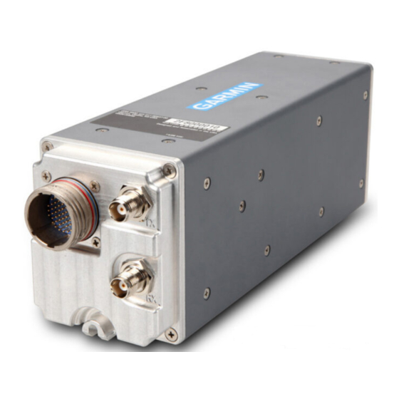
Garmin GRA 5500 Installation Manual (68 pages)
Radar Altimeter
Brand:
Garmin
| Category:
Measuring Instruments
| Size: 4.98 MB
Table of Contents
Table of Contents
8
Paragraph Page
9
Section 1 GENERAL DESCRIPTION
12
Introduction
12
Equipment Description
12
Interface Summary
12
Section 1 GENERAL DESCRIPTION
13
Technical Specifications
13
Environmental Qualification Form
13
Physical Characteristics
13
General Specifications
13
Table 1-1 Physical Characteristics
13
Table 1-2 General Specifications
13
Performance Specifications
14
Power Requirements
14
Certification
14
Table 1-3 Performance Specifications
14
Table 1-4 Power Requirements
14
TSO Compliance and Limitations
15
TSO Deviations
15
Operating Instructions
15
Reference Documents
15
Table 1-5 TSO Compliance
15
Table 1-6 Reference Documents
15
Section 2 INSTALLATION OVERVIEW
16
Section 2 INSTALLATION OVERVIEW
16
Introduction
16
Installation Materials
16
Available Equipment
16
Table 2-1 Available Units
16
Table 2-2 Available Equipment
16
Additional Equipment Required
17
Approved Radar Altimeter Antennas
17
Table 2-3 Additional Equipment Required
17
Table 2-4 Approved Radar Altimeter Antennas
17
Installation Considerations
18
Multiplex Operation (Dual and Triple Unit Installations)
18
Installation Approval Considerations for Pressurized Aircraft
18
Table 2-5 System ID Discrete Inputs
18
Antenna Location Planning Guidance
19
Figure 2-1 Standard Dual and Triple End-To-End System Layouts
21
Figure 2-2 Compact Dual and Triple End-To-End System Layouts
22
Figure 2-3 Dual and Triple Side-By-Side System Layouts
23
Figure 2-4 Hybrid Triple System Layout
24
Antenna Installation Considerations
25
Section 2 INSTALLATION OVERVIEW
21
Electrical Bonding
25
Cabling and Wiring
25
Antenna Coaxial Cables (Requirements and Fabrication Guidance)
26
Figure 2-5 Coaxial Cable Requirements
27
Figure 2-6 TNC Connector Installation
28
Figure 2-7 Heat Shrink Positioning
28
Cooling Requirements
29
Mounting Requirements
29
Figure 2-8 GRA 5500 Mounting Rack
29
Section 3 INSTALLATION PROCEDURE
30
Section 3 INSTALLATION PROCEDURE
30
Unpacking Unit
30
Wiring Harness Installation
30
Table 3-1 Pin Contact Part Numbers
30
Table 3-2 Recommended Crimp Tools
30
Table 3-3 Recommended Insertion Tools
30
Backshell Assembly
31
Antenna Installation
31
Unit Installation
31
Installation Procedure (See Figure 3-1)
31
Removal Procedure (See Figure 3-1)
31
Table 3-4 Recommended Removal Tools
31
Section 3 INSTALLATION PROCEDURE
32
Figure 3-1 GRA 5500 Installation
32
Downloading and Installing the GRA 5500 Retrofit Installation Tool
33
Post Installation Configuration and Checkout Procedures
34
GRA 5500 Configuration/Checkout for Varying Installation Types
34
Using the GRA 5500 Retrofit Installation Tool
35
Figure 3-2 GRA 5500 Retrofit Installation Tool (New Installation)
36
Figure 3-3 GRA 5500 Retrofit Installation Tool Status Tab (Normal Operation)
38
Figure 3-4 GRA 5500 Retrofit Installation Tool Configuration Tab
39
Table 3-5 ARINC 429 Channel 1 Settings
40
Table 3-6 ARINC 429 Channel 2 Settings
40
Figure 3-5 GRA 5500 Retrofit Installation Tool Software Tab
42
Zero-Foot Calibration
45
Built-In Self-Test Functionality
45
Continued Airworthiness
47
Section 4 SYSTEM INTERCONNECTS
48
Section 4 SYSTEM INTERCONNECTS
48
Section 4 SYSTEM INTERCONNECTS
48
Pin Function List
48
P55001
48
Figure 4-1 View of J55001 Connector, from Front of Unit
48
Table 4-1 P55001 Connector
48
Power Functions
50
Aircraft Power
50
Serial Data Connections
50
HSDB over RS-422
50
Table 4-2 Aircraft Power
50
Arinc 429
51
Configuration Module
51
Table 4-5 ARINC 429 Output Labels
51
Table 4-6 Configuration Module
51
Usb
52
Discrete I/O
52
Active Low Discrete Inputs
52
Table 4-7 USB Connections
52
Table 4-8 Active Low Discrete Inputs
52
Altitude Alert (Annunciator) Outputs
53
Table 4-9 Alert Outputs
53
Appendix A Referenced Tables
54
Appendix A Referenced Tables
54
Table A-1 Recommended Coaxial Length
54
Table A-2 TNC Connectors
55
Table A-3 GRA 5500 Fault Descriptions
56
Table A-4 "Various" POST (Power on Self-Test) Faults
60
Appendix B Outline and Installation Drawings
62
Figure B-1 GRA 5500 Outline Drawing
62
Appendix B Outline and Installation Drawings
63
Figure B-2 GRA 5500 Connector/Rack Assembly Drawing
63
Appendix C Interconnect Examples
64
Appendix C Interconnect Examples
64
Figure C-1 Garmin Integrated Flight Deck (GIFD) and Non-GIFD (Retrofit)
64
Figure C-2 Garmin Integrated Flight Deck Interconnect Example
65
Figure C-3 Non-Garmin Integrated Flight Deck (Retrofit) Interconnect Example
66
Figure C-4 GRA 5500 USB Dongle Cable
67
Figure C-5 GRA 5500 Configuration Module Interconnect Example
68
Advertisement
Advertisement
Related Products
Garmin GI 275
Garmin GRA 10
Garmin GRC 10 Remote Control
Garmin GRT 10 Transceiver
GARMIN GRID
Garmin GRF 10
Garmin GRS 77
Garmin GRN-010-02088-01
Garmin GPS 126
Garmin GPS 158
Garmin Categories
GPS
Watch
Car Navigation system
Avionics Display
Marine GPS System
More Garmin Manuals
Login
Sign In
OR
Sign in with Facebook
Sign in with Google
Upload manual
Upload from disk
Upload from URL