Sign In
Upload
Manuals
Brands
Fluidwell Manuals
Measuring Instruments
F043-A
Fluidwell F043-A Manuals
Manuals and User Guides for Fluidwell F043-A. We have
1
Fluidwell F043-A manual available for free PDF download: Manual
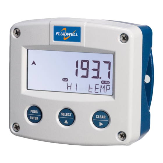
Fluidwell F043-A Manual (52 pages)
TEMPERATURE MONITOR WITH HIGH / LOW TEMPERATURE ALARMS
Brand:
Fluidwell
| Category:
Measuring Instruments
| Size: 2 MB
Table of Contents
Safety Instructions
2
Disposal of Electronic Waste
2
Safety Rules and Precautionary Measures
2
About the Manual
3
Warranty and Technical Support
3
Table of Contents
4
Contents Manual
4
Introduction
6
System Description of the F043-A
6
Fig. 1: Typical Application for the F043-A
6
Operational
7
General Information
7
Control Panel
7
Operator Information and Functions
7
Fig. 2: Control Panel
7
Fig. 3: Example of Display Information During Process
7
Fig. 4: Example of Display Information During Programming Minimum Alarm Temperature
8
Fig. 5: Example of Low-Battery Alarm
8
Configuration
9
Introduction
9
Programming SETUP-Level
9
Entering SETUP-Level
9
Navigating through SETUP-Level
9
Fig. 6: SETUP Matrix Structure
9
Programming Sequence
10
Returning to OPERATOR-Level
11
Configuration Settings
12
Overview Functions SETUP Level
12
Explanation of SETUP-Menu 1 - Temperature
13
Explanation of SETUP-Menu 2 - Alarm
13
Explanation of SETUP-Menu 3 - Display
14
Explanation of SETUP-Menu 4 - Power Management
14
Explanation of SETUP-Menu 5 - Sensor
15
Explanation of SETUP-Menu 6 - Others
16
Installation
17
General Directions
17
Installation / Surrounding Conditions
17
Handling the F-Series Enclosure
18
Identification
18
Fig. 7: Identification - Example of F0-Series Identification Label (Safe Area)
18
Fig. 8: Identification - Example of F0-Series Installation Label (Safe Area - Type PB, PX or PD)
18
Fig. 9: Identification - Example of F0-Series Installation Label (Safe Area - Type PF or PM)
19
Opening / Removing the Cover
20
Closing / Replacing the Cover
20
Mechanical Installation
21
Dimensions - Aluminum and Stainless Steel Enclosures
21
Fig. 10: Dimensions - Aluminum and Stainless Steel Enclosures
21
Dimensions - Non-Metallic Enclosures
22
Fig. 11: Dimensions - Non-Metallic Enclosures
22
Mounting
23
Fig. 12: Installation - Mounting Configurations
23
Electrical Installation
24
Electrical Safety
24
Protective Earth (PE) Connections
24
Field Wiring Connections
25
Fig. 13: Protective Earth (PE) Connections on Metal Enclosure
25
Power Supply Wiring
26
Sensor Supply
26
Fig. 14: Switch Position Voltage Selection (Type PF and PM)
26
Terminal Connectors Safe Area Applications - Type PB / PD / PL / PX
27
Terminals 1-2: Sensor Input
27
Fig. 15: Overview of Terminal Connectors F043-A - Type PB / PD / PL / PX
27
Fig. 16: Terminal Connections - Analog Signal Input
27
Terminal 4-5: Power Supply - Type PX (Default) and PD (Option)
28
Terminal 7-8: Alarm Output - Type OT (Option)
28
Terminal 9-10: Power Supply Backlight - Type ZB (Option)
28
Terminal Connectors Safe Area Applications - Type PF / PM
28
Fig. 17: Terminal Connections - Passive Transistor Output (Type OT)
28
Fig. 18: Terminal Connections - Backlight (ZB)
28
Fig. 19: Overview of Terminal Connectors F043-A - Type PF / PM
28
Terminal GND-1-2: Power Supply
29
Terminals 3-4: Alarm Output
29
Fig. 20: Terminal Connections - Passive Transistor Output (OT)
29
Fig. 21: Terminal Connections - Active Transistor Output (OA)
29
Fig. 22: Terminal Connections - Mechanic Relay Output (OR)
29
Terminals 5-7: Sensor Input
30
Fig. 23: Terminal Connections - Analog Signal Input
30
Intrinsically Safe Applications
31
Identification
31
Fig. 24: Identification - Example of F0-Series Identification Label (Intrinsic Safety)
31
Fig. 25: Identification - Example of F0-Series Installation Label (Intrinsic Safety)
31
Electrical Installation in Hazardous Area
32
General Information and Instructions
32
Installations Based on FM or CSA Certificate
32
Electrical Data - Control Drawing
33
Installations Based on ATEX or Iecex Certificate
35
Electrical Data - Annex 1
36
Terminal Connectors Intrinsically Safe Applications
37
Power Supply Wiring
37
Terminal 6 - Type PD: Sensor Supply
37
Fig. 26: Overview Terminal Connectors Type XI - Intrinsically Safe Applications
37
Configuration Examples Intrinsically Safe Applications
38
F043-A-OT-PX-XI-ZB - Ex Ia IIC/IIIC
38
F043-A-OT-PD-XI-ZB - Ex Ia IIC/IIIC
38
Fig. 27: F043-A-OT-PX-XI-ZB - Ex Ia IIC/IIIC - Intrinsically Safe Application
38
Fig. 28: F043-A-OT-PD-XI-ZB - Ex Ia IIC/IIIC - Intrinsically Safe Application
38
F043-A-OT-PL-XI-ZB - Ex Ia IIC/IIIC
39
Fig. 29: F043-A-OT-PL-XI-ZB - Ex Ia IIC/IIIC - Intrinsically Safe Application
39
Maintenance
40
General Directions
40
Instructions for Repair
40
Battery Replacement
41
Safety Instructions
41
Fig. 30: Marking Type PC Battery: Intrinsically Safe FW-Libat-021 (SPC02)
41
Fig. 31: Marking Type PB Battery: Safe Area Stdlibat021 (SPB02)
41
Replace the Battery
42
Disposal of Batteries
42
Fig. 32: Battery Replacement Procedure
42
Technical Specification
43
Problem Solving
46
Declaration of Conformity
47
Index of this Manual
48
List of Figures
49
Advertisement
Advertisement
Related Products
Fluidwell F043-T
Fluidwell F040-T
Fluidwell F040-U
Fluidwell F040-A
Fluidwell F093-P
Fluidwell F012-A
Fluidwell F011-P
Fluidwell F018-P
Fluidwell F090
Fluidwell F090-A-PL
Fluidwell Categories
Measuring Instruments
Controller
Monitor
Desktop
Touch Panel
More Fluidwell Manuals
Login
Sign In
OR
Sign in with Facebook
Sign in with Google
Upload manual
Upload from disk
Upload from URL