Sign In
Upload
Manuals
Brands
Carrier Manuals
Chiller
AquaEdge 19XR
Carrier AquaEdge 19XR Manuals
Manuals and User Guides for Carrier AquaEdge 19XR. We have
3
Carrier AquaEdge 19XR manuals available for free PDF download: Start-Up, Operation And Maintenance Instructions Manual, Controls Operation And Troubleshooting
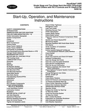
Carrier AquaEdge 19XR Start-Up, Operation And Maintenance Instructions Manual (128 pages)
Single Stage and Two-Stage Semi-Hermetic Centrifugal Liquid Chillers with PIC 6 Controls and R-134a/R-513A 50/60 Hz
Brand:
Carrier
| Category:
Chiller
| Size: 20.01 MB
Table of Contents
Table of Contents
1
Safety Considerations
2
Introduction
4
Abbreviations and Explanations
4
Chiller Familiarization (Fig. 1-5)
4
Chiller Information Nameplate
4
System Components
4
Cooler
4
Condenser
4
Motor-Compressor
4
Control Panel
4
Power Panel (19XR2-E)
5
Power Panel (19XR6/7)
5
Economizer (if Available)
5
Free-Standing/Factory-Mounted Starter or VFD
5
Storage Vessel (Optional)
5
Refrigeration Cycle
11
Motor and Oil Cooling Cycle
12
VFD Cooling Cycle
12
Lubrication Cycle
13
Summary
13
Details
13
Bearings
13
Oil Reclaim System
13
Starting Equipment
16
Unit-Mounted Vfds
16
Unit-Mounted Starters
16
Solid-State Starter
16
Wye-Delta Starter
16
Free-Standing Starters/Vfds
17
Controls
17
Definitions
17
General
17
PIC 6 System Components
17
Start-Up/Shutdown
19
Recycle Sequence
19
Local Start/Stop Control
19
Lubrication Control
20
Shutdown
20
Before Initial Start-Up
20
Job Data Required
20
Equipment Required
20
Remove Shipping Packaging
20
Open Oil Circuit Valves
20
Tighten All Gasketed Joints
21
Check Chiller Tightness
21
Refrigerant Tracer
23
Leak Test Chiller
23
Standing Vacuum Test
23
Chiller Dehydration
25
Inspect Water Piping
25
Check Relief Valves
25
Check the Optional Pumpout Compressor Water
25
Piping
25
Identify and Check Starter/Vfd
25
Mechanical Starter
26
Benshaw Redistart MX3 Solid-State Starter
26
VFD Starter
26
Verify Condition of Installation
26
Inspect Wiring
26
Carrier Comfort Network ® (CCN) and Local Equipment Network (LEN) Interface
27
Check Starter
27
Oil Charge
28
Power up Controls and Check Oil Heater
28
Software Configuration
28
Input the Design Set Points
28
Input the Local Occupied Schedule
28
Input Service Configurations
29
Field Set up and Verification
31
Perform a Controls Test (Quick Test/Quick Calibration)
34
Check Optional Pumpout System Controls and Compressor
34
Charge Refrigerant into Chiller
34
Initial Start-Up
37
Preparation
37
Check Motor Rotation
37
Check Oil Pressure and Compressor Stop
37
To Prevent Accidental Start-Up
37
Check Chiller Operating Condition
37
Instruct the Customer Operator
37
Operating Instructions
38
Operator Duties
38
Prepare the Chiller for Start-Up
38
To Start the Chiller
38
Check the Running System
38
To Stop the Chiller
38
After Limited Shutdown
38
Preparation for Extended Shutdown
38
After Extended Shutdown
39
Cold Weather Operation
39
Manual Guide Vane Operation
39
Refrigeration Log
39
Pumpout and Refrigerant Transfer Procedures
39
Preparation
39
Operating the Optional Pumpout Unit (Fig. 37)
41
General Maintenance
44
Refrigerant Properties
44
Adding Refrigerant
44
Adjusting the Refrigerant Charge
44
Refrigerant Leak Testing
44
Leak Rate
44
Test after Service, Repair, or Major Leak
44
Repair the Leak, Retest, and Apply Standing Vacuum Test
44
Checking Guide Vanes
44
Trim Refrigerant Charge
44
Weekly Maintenance
47
Check the Lubrication System
47
Scheduled Maintenance
47
Service Ontime
47
Inspect the Control Panel
47
Changing Oil Filter
47
Oil Specification
47
Oil Changes
47
Refrigerant Filter
47
VFD Refrigerant Strainer (if Equipped)
48
Oil Reclaim Filter
48
Inspect Refrigerant Float System
48
Inspect Relief Valves and Piping
49
Compressor Bearing and Gear Maintenance
49
Inspect the Heat Exchanger Tubes and
49
Flow Devices
49
Water Leaks
49
Water Treatment
49
Inspect the Starting Equipment or VFD
50
Recalibrate Pressure Transducers
50
Optional Pumpout System Maintenance
50
Ordering Replacement Chiller Parts
50
Troubleshooting Guide
51
Overview
51
Checking Display Messages
51
Checking Temperature Sensors
51
Checking Pressure Transducers
55
High Altitude Locations
55
Quick Test
55
Pumpdown/Lockout
55
Physical Data
55
Appendix A - Pic 6 Screen and Table Structure
109
Appendix B - Ccn Communication Wiring for Multiple Chillers (Typical)
111
Appendix C - Maintenance Summary
112
And Log Sheets
112
Index
115
Initial Start-Up Checklist
117
Centrifugal Liquid Chiller
117
Advertisement
Carrier AquaEdge 19XR Start-Up, Operation And Maintenance Instructions Manual (112 pages)
Two-Stage Semi-Hermetic Centrifugal Liquid Chillers with PIC 5 Controls and HFC-134a 50/60 Hz
Brand:
Carrier
| Category:
Chiller
| Size: 15.27 MB
Table of Contents
Table of Contents
1
Safety Considerations
2
Introduction
3
Abbreviations and Explanations
4
Chiller Familiarization (Fig. 1 and 2)
4
Chiller Information Nameplate
4
System Components
4
Cooler
4
Condenser
4
Motor-Compressor
4
Control Panel
4
Economizer
4
Free-Standing Starter
4
Refrigeration Cycle
7
Motor and Oil Cooling Cycle
8
Lubrication Cycle
8
Summary
8
Details
8
Bearings
8
Oil Reclaim System
8
Starting Equipment
10
Solid-State Starter (Optional)
10
Free-Standing Medium Voltage VFD (Optional)
10
Controls
11
Definitions
11
General
11
PIC 5 System Components
11
Start-Up/Shutdown/ Recycle Sequence
11
Local Start/Stop Control
11
Lubrication Control
12
Shutdown
12
Before Initial Start-Up
13
Job Data Required
13
Equipment Required
13
Remove Shipping Packaging
13
Open Oil Circuit Valves
13
Tighten All Gasketed Joints
13
Check Chiller Tightness
13
Refrigerant Tracer
16
Leak Test Chiller
16
Standing Vacuum Test
16
Chiller Dehydration
18
Inspect Water Piping
18
Check Relief Valves
18
Inspect Wiring
18
Check Starter
19
Oil Charge
19
Power up Controls and Check Oil Heater
19
Software Configuration
19
Input the Design Set Points
20
Input the Local Occupied Schedule
20
Input Service Configurations
20
Field Set up and Verification
22
Perform a Controls Test (Quick Test/Quick Calibration)
24
Charge Refrigerant into Chiller
24
Initial Start-Up
30
Preparation
30
Check Motor Rotation
30
Check Oil Pressure and Compressor Stop
30
To Prevent Accidental Start-Up
30
Check Chiller Operating Condition
30
Instruct the Customer Operator
30
Operating Instructions
31
Operator Duties
31
Prepare the Chiller for Start-Up
31
To Start the Chiller
31
Check the Running System
31
To Stop the Chiller
31
After Limited Shutdown
31
Preparation for Extended Shutdown
31
After Extended Shutdown
32
Cold Weather Operation
32
Manual Guide Vane Operation
32
Refrigeration Log
32
Pumpout and Refrigerant Transfer Procedures
32
Preparation
32
Operating the Optional Pumpout Unit (Fig. 27)
34
General Maintenance
36
Refrigerant Properties
36
Adding Refrigerant
37
Adjusting the Refrigerant Charge
37
Refrigerant Leak Testing
37
Leak Rate
37
Test after Service, Repair, or Major Leak
37
Repair the Leak, Retest, and Apply Standing Vacuum Test
37
Checking Guide Vanes
37
Changing Oil Filter
39
Trim Refrigerant Charge
39
Weekly Maintenance
39
Check the Lubrication System
39
Scheduled Maintenance
39
Service Ontime
39
Inspect the Control Panel
39
Oil Specification
40
Oil Changes
40
Refrigerant Filter
40
Oil Reclaim Filter
40
Inspect Refrigerant Float System
40
Inspect Relief Valves and Piping
41
Compressor Bearing and Gear Maintenance
41
Inspect the Heat Exchanger Tubes and Flow Devices
41
Water Leaks
42
Water Treatment
42
Inspect the Starting Equipment
42
Recalibrate Pressure Transducers
42
Optional Pumpout System Maintenance
42
Ordering Replacement Chiller Parts
42
Troubleshooting Guide
43
Overview
43
Checking Display Messages
43
Checking Temperature Sensors
43
Checking Pressure Transducers
47
High Altitude Locations
47
Quick Test
47
Pumpdown/Lockout
47
Physical Data
47
Appendix A: Pic
72
Screen and Menu Structure
91
Carrier AquaEdge 19XR Controls Operation And Troubleshooting (108 pages)
Two-Stage High-Efficiency Semi-Hermetic Centrifugal Liquid Chillers with PIC 5 Controls
Brand:
Carrier
| Category:
Chiller
| Size: 9.06 MB
Table of Contents
Table of Contents
1
Safety Considerations
1
General
2
Abbreviations Used in this Manual
2
Hardware
2
Main Control Board
2
ISM (Integrated Starter Module)
2
IOB (Input/Output Board)
3
Communication Cables
3
Sensors
12
Pressure Transducers
12
Temperature Sensors
12
Controls Outputs
12
Evaporator/Condenser Water Pump
12
Inlet Guide Vane
12
Economizer Damper Valve
12
Envelop Control/Hgbp Valve
12
Pic 5 User Interface
12
Web Connection
12
General Interface Features
13
Icons
13
Pic 5 Control Operation
17
Start-Stop Control
17
Local Schedule
17
Compressor Run Status
17
Chiller Start-Up Sequence
18
Startup
18
Chiller Shutdown Sequence
19
Oil Lubrication Control
19
Control Points
19
Set Point
19
Control Point Temperature
19
Temperature Reset
19
Capacity Control
19
Ramp Loading
20
Surge Correction Control
21
Envelop/Hot Gas Bypass (Hgbp) Control
21
Economizer Damper Valve Control
21
Demand Limit
22
Water Pumps Control (Freeze Prevention)
23
Control Test
24
Swift Restart
24
Cooling Tower Control
24
Head Pressure Control
24
Ice Build Option
24
Time Schedule
24
Black Box
24
Pressure Transducer Calibration
24
Temperature Sensor Calibration
25
Ism Vfd Input/Output Calibration
26
Alarm Email
27
Master Slave Control
29
Oil EXV Option
30
Pumpdown/Lockout
30
Displaying Data Trends
30
Hydraulic Option
31
Water Flow Measurement
31
Water Pressure Difference Measurement
31
Marine Option(S)
31
Diagnostics and Troubleshooting
32
Displaying Alarms
32
Resetting Alarms
32
Alarm/Alert Codes
32
Event States
49
Touch Screen Settings for the Controller
49
Unit IP Address
49
Web Address
50
System Configuration
50
General Display Settings
51
Touch Screen Calibration
51
Touch Screen Configuration Language
51
Communication Problems
52
Hardware Problems
52
Web Interface Problems
52
Ethernet/Ip Connection Problems
53
Unit Is Point-To-Point Connected to a Pc
53
Unit Is Connected to the Local Network
53
Ethernet Connection on the Pc
54
Java Application Configuration
54
Appendix A - Pic 5 Screen and Table
55
Structure
55
Appendix B - Input/Output Board (Iob) and Human Machine Interface (Hmi) Dip Switch Settings
92
Appendix C - Input/Output Board (Iob) Status Indicators
94
Appendix D - Network Configuration
95
Appendix E - Ism Wiring Diagrams
102
Advertisement
Advertisement
Related Products
Carrier AquaEdge 23XRV
Carrier AQUAFORCE 30XA080-500
Carrier AQUASNAP 30RB060-390
Carrier AquaForce B Series
Carrier Aqua Force 30XA 252
Carrier Aqua Force 30XA 302
Carrier Aqua Force 30XA 502
Carrier Aqua Force 30XA 602
Carrier Aqua Force 30XA 702
Carrier Aqua Force 30XA 852
Carrier Categories
Air Conditioner
Heat Pump
Furnace
Thermostat
Chiller
More Carrier Manuals
Login
Sign In
OR
Sign in with Facebook
Sign in with Google
Upload manual
Upload from disk
Upload from URL