Table of Contents
Advertisement
Quick Links
EMPIRE
EMPIRE
Comfort Systems
LUXURY DIRECT VENT
GAS FIREPLACE HEATER
MILLIVOLT STANDING PILOT (MV)
DVX(36,42)DP31(N,P)-3
DIRECT IGNITION (DI)
DVX(36,42)DP51N-2
INTERMITTENT PILOT (IP)
DVX(36,42)DP71(N,P)-4
REMOTE RF (RF)
DVX(36,42)DP91(N,P)-4
UL FILE NO. MH30033
GAS-FIRED
: If not installed, operated and maintained
WARNING
in accordance with the manufacturer's instructions,
this product could expose you to substances in fuel
or from fuel combustion which can cause death or
serious illness.
This appliance may be installed in an aftermarket,
permanently located, manufactured home (USA only)
or mobile home, where not prohibited by state or local
codes.
This appliance is only for use with the type of gas
indicated on the rating plate. This appliance is not
convertible for use with other gases, unless a certified
kit is used.
INSTALLATION INSTRUCTIONS
OWNER'S MANUAL
Installer:
Consumer: Retain this manual for future reference.
WARNING
tions are not followed exactly, a fire or explosion
may result causing property damage, personal in-
jury or loss of life.
— Do not store or use gasoline or other flammable
vapors and liquids in the vicinity of this or any
other appliance.
— WHAT TO DO IF YOU SMELL GAS
•
•
•
•
— Installation and service must be performed by a
qualified installer, service agency or the gas sup-
plier.
AND
Direct Vent Zero Clearance Gas
Fireplace Heater
Leave this manual with the appliance.
: If the information in these instruc-
Do not try to light any appliance.
Do not touch any electrical switch; do not use
any phone in your building.
Immediately call your gas supplier from a
neighbor's phone. Follow the gas supplier's
instructions.
If you cannot reach your gas supplier, call the
fire department.
Page 1
Advertisement
Table of Contents
Troubleshooting

Subscribe to Our Youtube Channel
Related Manuals for Empire Comfort Systems DVX42DP31P-3


Summary of Contents for Empire Comfort Systems DVX42DP31P-3
-
Page 1: Installation Instructions
INSTALLATION INSTRUCTIONS EMPIRE EMPIRE OWNER’S MANUAL Comfort Systems Direct Vent Zero Clearance Gas LUXURY DIRECT VENT Fireplace Heater GAS FIREPLACE HEATER MILLIVOLT STANDING PILOT (MV) DVX(36,42)DP31(N,P)-3 DIRECT IGNITION (DI) DVX(36,42)DP51N-2 INTERMITTENT PILOT (IP) DVX(36,42)DP71(N,P)-4 REMOTE RF (RF) DVX(36,42)DP91(N,P)-4 Installer: Leave this manual with the appliance. Consumer: Retain this manual for future reference. -
Page 2: Table Of Contents
TABLE OF CONTENTS Section Page IMPORTANT SAFETY INFORMATION ..............................3 SAFETY INFORMATION FOR USERS OF LP GAS ..........................4 REQUIREMENTS FOR MASSACHUSETTS ............................5 INTRODUCTION ....................................6 SPECIFICATIONS ....................................7 SPECIAL VENT SYSTEMS ...................................7 VENT SYSTEM IDENTIFICATION ................................8 FIREPLACE DIMENSIONS ...................................9 CLEARANCES .....................................10 LOCATING FIREPLACE ..................................11 GAS SUPPLY .......................................12 INSTALLATION .................................... -
Page 3: Important Safety Information
IMPORTANT SAFETY INFORMATION Before enclosing the vent pipe assembly, operate the appliance to ensure it is venting properly. DO NOT OPERATE THIS APPLIANCE WITHOUT GLASS FRONT PANEL INSTALLED • Young children should be carefully supervised when they DANGER: Indicates a hazardous situation which, if not are in the same room as the appliance. -
Page 4: Safety Information For Users Of Lp Gas
SAFETY INFORMATION FOR USERS OF LP GAS Propane (LP-Gas) is a flammable gas which can cause fires with the members of your household. Someday when there and explosions. In its natural state, propane is odorless and may not be a minute to lose, everyone’s safety will depend colorless. -
Page 5: Requirements For Massachusetts
REQUIREMENTS FOR MASSACHUSETTS For all side wall horizontally vented gas fueled equipment installed SIGNAGE. A metal or plastic identification plate shall be in every dwelling, building or structure used in whole or in part for permanently mounted to the exterior of the building at a residential purposes, including those owned or operated by the minimum height of eight feet above grade directly in line with Commonwealth and where the side wall exhaust vent termination... -
Page 6: Introduction
Modification of the fireplace or direct vent system. The installation must conform with local codes or, in the absence of • Installation other than as instructed by Empire Comfort Systems, local codes, with the National Fuel Gas Code ANSI Z223.1/NFPA Inc. -
Page 7: Specifications
SPECIFICATIONS DVX36 NAT DVX36 LP DVX42 NAT DVX42 LP Input Btu/hr Maximum 35,000 30,000 37,500 35,000 Btu/hr Minimum 24,500 21,000 26,000 28,000 KWH (Maximum) 10.3 10.3 (Minimum) Orifice - MV, IP, RF #32 (P211) 1.65 mm (P250) #31 (P209) #50 (P245) Orifice - DI 2.75mm (P305) 1.65 mm (P250) -
Page 8: Vent System Identification
*Note: If using three 90° elbows during horizontal termination, see Figure 30. Special Venting Components (Simpson Duravent) See Empire COmfort SYstems Retail Price List for Simpson Duravent part numbers and pricing. Special DV Vent Kits are available from Empire Comfort Systems Inc. dealers. -
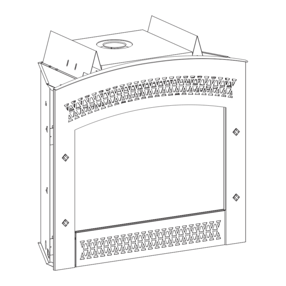
Page 9: Fireplace Dimensions
FIREPLACE DIMENSIONS Dimension DVX36DP DVX42DP 34 3/4" (882.7 mm) 34 3/4" (882.7 mm) 39" (990.6 mm) 43" (1092.2 mm) 19 7/8" (505 mm) 19 7/8" (505 mm) 25" (635 mm) 25" (635 mm) 36" (914.4 mm) 40" (1016 mm) 26 1/2" (673.1 mm) 26 1/2"... -
Page 10: Clearances
CLEARANCES Mantel Chart Clearance to Combustibles Back 0" (0 mm) Side 0" (0 mm) Floor 0" (0 mm) Top Stand-off 0" (0 mm) Top Framing Edge 6" (152 mm) Figure 5 Clearances Clearance from top front edge of fireplace to ceiling is 36” Clearance from side of fireplace to adjacent sidewall is 6”. -
Page 11: Locating Fireplace
LOCATING FIREPLACE Notice: Island and Room Divider installation is possible as long as When you install your Direct Vent Fireplace in Room divider or Flat the horizontal portion of the vent system does not exceed 20 feet on wall corner positions, a minimum of 6 inches clearance must be with a minimum vertical run of 8 feet. -
Page 12: Gas Supply
GAS SUPPLY The gas pipeline can be brought in through the right or left side of Installing a New Main Gas Cock the appliance. Consult the current National Fuel Gas Code, ANSI Each appliance should have its own manual gas cock. Z223.1 CAN/CGA-B149 (.1 or .2) installation code. -
Page 13: Installation
INSTALLATION Framing and Finishing Choose unit location. Frame in fireplace with a header across the top. It is important to allow for finished face when setting the depth of the frame. See Figure 11. Attach fireplace to frame using adjustable nailing flange. Preset depth to suit facing material (adjustable to 3/8”, 1/2”... - Page 14 INSTALLATION (continued) DVX36 DVX42 "A" 40 7/8" 40 7/8" "B" 40 3/8" 43 3/8" "C" 19 7/8" 19 7/8" Figure 13 Figure 14 Attention: When fireplace is installed in optional full cabinet mantel Attention: Add 3-3/4” to “A” dimensions when using a flush mantel or corner mantel the four nailing flanges shown in Figure 10 will base.
- Page 15 INSTALLATION (continued) Flush Wall Installation Attention: Cold climate installation recommendation: When installing this unit against a non-insulated exterior wall, it is recommended that the outer walls be insulated to conform to applicable insulation codes. Vent Runs In planning the installation for the fireplace, it is necessary to install certain components before the appliance is completely positioned and installed.
-
Page 16: Installation
INSTALLATION (continued) VERTICAL, 90° ELBOW TO CORNER INSTALLATION VERTICAL, 90° ELBOW TO HORIZONTAL OUT THE WALL HORIZONTAL OUT THE WALL Dim. DVX36 DVX42 45 3/8" (1152 mm) 49 5/8" (1260 mm) "A" "B" "C" 32 1/8" (816 mm) 35 1/8" (892 mm) 6"(152 mm) 11 1/4"(286 mm) to 4 3/4"(121 mm) to... -
Page 17: Venting Fireplace - Top
VENTING FIREPLACE - TOP Venting Graph (Dimensions in Feet) To Use the Vent Graph 1. Determine the height of the center of the horizontal vent pipe. Using this dimension on the Sidewall Vent Graph, locate the point it intersects with the slanted graph line. 2. - Page 18 VENTING FIREPLACE - TOP (continued) Installation of Flue Heat Shield Remove flue insulation. Remove two screws on outside of inlet vent adapter. See Figure 21. Lift top shield placing flue heat shield around flue. Replace two screws on outside of inlet vent adapter. See Figure 22.
- Page 19 VENTING FIREPLACE - TOP (continued) Below Grade Installation When it is not possible to meet the required vent terminal clearances of 12” (305mm) above grade level, a snorkel kit is recommended. It allows installation depth down to 7” (178 mm) below grade level. The 7”...
- Page 20 VENTING FIREPLACE - TOP (continued) Figure 27 Figure 26 MINIMUM HOLE LOCATION DIMENSIONS FOR THROUGH THE WALL HORIZONTAL INSTALLATIONS WITH 90 DEGREE ELBOW OFF TOP OF FIREPLACE HARD ELBOW DIMENSIONS FIREPLACE SERIES "A" "B" "C" 43-1/2" 5" 7" DVX36FP (1105 mm) (127 mm) (178 mm) 43-1/2"...
-
Page 21: Examples - Top Vent Run
EXAMPLES - TOP VENT RUN Figure 30 Figure 29 Figure 31 31453-6-0914 Page 21... -
Page 22: Vent Clearances
VENT CLEARANCES AREA WHERE TERMINAL IS NOT PERMITTED VENT TERMINAL AIR SUPPLY INLET Figure 32 *Clearance above grade, veranda, porch, deck or balcony clearance to a mechanical air supply inlet [* 6 feet (1.8m) [*12 inches (30cm) minimum] minimum] clearance to window or door that may be opened [*12 inches †clearance above paved sidewalk or a paved driveway (30cm) minimum for appliances <... -
Page 23: Framing And Finishing
FRAMING AND FINISHING Installing Support Brackets A horizontal pipe support MUST BE used for each 3 feet of horizontal run. The pipe supports should be placed around the pipe and nailed in place to framing members. There MUST BE a 3 inch clearance to combustibles above flue pipe and elbows and 1 inch clearance on both sides and bottom of the flue pipe to combustibles on all horizontal pipe sections and elbows. - Page 24 FRAMING AND FINISHING (continued) Vent Size Vent Size 6 5/8" 10" 10" 6 5/8" 10" 10" 8" 10 1/2" 10 1/2" 8" 10 1/2" 10 1/2" Figure 37 Figure 35 See Horizontal Termination Page 26 and Vertical Termination Pages 27 and 28. Vent Size 6 5/8"...
-
Page 25: Termination Clearances
TERMINATION CLEARANCES Termination clearance for buildings with combustible and noncombustible exteriors. Figure 38 Vertical Sidewall Installations Important! Minimum clearance between vent pipes and combustible materials is three 3" (76 mm) on top, and 1" (25 mm) on bottom and sides. Important! When vent termination exits through foundation less than 20"... -
Page 26: Horizontal Termination
HORIZONTAL TERMINATION Notice: Termination cap should pass through the wall firestop from The vinyl siding standoff will be installed between the vent termination the exterior of the building. Adjust the termination cap to and the exterior wall. See Figure 39. This horizontal vent termination its final exterior position on the building. -
Page 27: Vertical Termination
VERTICAL TERMINATION Locate and mark the center point of the venting pipe. Using a nail on the underside of the roof and drive this nail through this center point. Make the outline of the roof hole around this center point. Notice: Size of the roof hole dimensions depend on the pitch of the roof. - Page 28 VERTICAL TERMINATION (continued) Vertical Through the Roof Applications Your Gas Fireplace has been approved for: a) Vertical installations up to 40 feet in height. b) Two sets of 45 degree elbow offsets within these vertical installations. From 0 to a maximum of 8 ft. a vent pipe can be used between elbows.
-
Page 29: Dvvk-4F Flex Vent Instructions
DVVK-4F FLEX VENT INSTRUCTIONS Remove the 6-⅝” diameter vent collar from the fireplace. The DVVK-4F FLEX VENT KIT includes the following compo- Replace this collar with the 7” diameter Flex Vent adapter nents: collar provided with the vent kit. • Horizontal Termination Cap Slide the Flex Vent flue pipe into the Outer Flex Vent pipe. -
Page 30: Dvvk-4Fv Direct Vent Termination Kit
DVVK-4FV DIRECT VENT TERMINATION KIT This termination kit can only be used with Empire Comfort Sys- IMPORTANT SAFETY INFORMATION tems direct vent fireplaces listed for use with DVVK-4FV Vertical • The vertical termination cap MUST be vented directly to the Flex Vent Kit. - Page 31 DVVK-4FV DIRECT VENT TERMINATION KIT (cont.) PRE-INSTALLATION INFORMATION: Installation of the Vertical Flex Termination Kit WARNING Items Required For Installation: Ensure that the venting system exits the structure through the roof and does not terminate less than 12 inches (305 mm) Tools Building Supplies above the roof.
- Page 32 DVVK-4FV DIRECT VENT TERMINATION KIT (cont.) Next, determine the location for the cutout in the roof opening. Step-By-Step Installation This opening must be large enough to provide a minimum 1” Unpack vent components and check all items for shipping air space clearance from the vertical vent pipe to any combus- damage.
- Page 33 DVVK-4FV DIRECT VENT TERMINATION KIT (cont.) 10. With the flex vent assembly and the 48” long hard pipe com- ponents laid out on the floor, begin securing these parts to- gether. First, apply a generous bead of silicone sealant to the inside of the 4”...
- Page 34 DVVK-4FV DIRECT VENT TERMINATION KIT (cont.) 17. To attach the vent connections at the fireplace, be sure the 7” diameter adapter collar has been installed per step 3. Apply a bead of silicone sealant to the 4” diameter flex connector, then slide the flex pipe adapter collar into the fireplace flue collar and secure by installing a minimum of two screws through the flue collar and into the adapter.
- Page 35 DVVK-4FV DIRECT VENT TERMINATION KIT (cont.) Figure 54 31453-6-0914 Page 35...
-
Page 36: Dvvk-4Fv Direct Vent Termination Kit
DVVK-4FV DIRECT VENT TERMINATION KIT (cont.) Vertical Flex Termination Kit Item Quantity Number Item Description Repair Part No. Supplied 4”/7” Vertical Termination Cap MF100038 Roof Support Kit MF100503 2 Ply Alum Flex 4” Diameter by 6 ft. MF04ALA2F006 2 Ply Alum Flex 7” Diameter by 6 ft. MF07ALA2F006 4”/7”... -
Page 37: Dvvk-4Re Vent Kit Installation Instructions
DVVK-4RE VENT KIT INSTALLATION INSTRUCTIONS Installing Wall Thimble/Firestop Assembly CAUTION: Sharp edges, use protective gloves when install- Fix fireplace to permanent location. If using rigid venting system, ing. install up to the location where it will exit the building. Tools Needed for Installation: Cut hole in wall for wall thimble/firestop assembly into your Sheet metal snips combustible wall. - Page 38 DVVK-4RE VENT KIT INSTALLATION INSTRUCTIONS (continued) Cutting Vent Tubes Remove outside mounting plate with tube attached from wall. This is the most important part of the installation. With the Mark and cut the extra length of the 6 5/8” (168 mm) diameter fireplace (and the rigid venting system if used) fixed to its permanent tube from the opposite end.
-
Page 39: Dvvk-4Re Vent Kit Installation Instructions
DVVK-4RE VENT KIT INSTALLATION INSTRUCTIONS (continued) Follow correct option according to venting method. Connecting to Rigid Vent System If the air inlet and flue outlet tubes are to be connected to a rigid Connecting Directly to Fireplace venting system (and not directly to the back of the unit), then do If the air inlet and flue outlet tubes are to be connected directly to not use the gasket provided. -
Page 40: Dvvk-5F Flex Vent Instructions
DVVK-5F FLEX VENT INSTRUCTIONS The DVVK-5F FLEX VENT KIT includes the following compo- Use existing 8” diameter inlet collar to attach outer vent pipe. nents: Install the Wall Firestop/Thimble assembly as required • Horizontal Termination Cap through the wall. Refer to the venting charts in the fireplace •... -
Page 41: Propane/Lp Gas Conversion
PROPANE/LP GAS CONVERSION Maxitrol Valve Conversion (Direct Ignition) Model AIR SHUTTER BURNER ORIFICE SETTINGS Opening "A" Propane/LP Orifice Figure 64 DVX36 FULL OPEN 1.65 MM DVX42 FULL OPEN 1.80 MM Figure 63 31453-6-0914 Page 41... -
Page 42: Log Identification
LOG IDENTIFICATION REAR BOTTOM LOG (A) REAR TOP LOG (B) Part Number - R9228 Part Number - R9222 BOTTOM LEFT LOG (C) BOTTOM LEFT CENTER LOG (D) Part Number - R9227 Part Number - R9372 BOTTOM RIGHT CENTER LOG (E) BOTTOM RIGHT LOG (F) Part Number - R9225 Part Number - R9229... -
Page 43: Log Placement (13 Log Set)
LOG PLACEMENT (13 LOG SET) Before you begin: If you are installing logs into the DVX36 or DVX42 Place Bottom Left Log (C) on far left pin of burner. The “lip” of model then this fireplace is supplied with a set of 13 ceramic fiber the log will hang off the side of the burner. - Page 44 LOG PLACEMENT (13 LOG SET) Place Bottom Right Log (F) on far right pin on the burner. The 12. Place Top Left Log (I) on two left pins on (B) Log. “lip” of the log will hang off the side of the burner. 13.
- Page 45 LOG PLACEMENT (13 LOG SET) 15. Place Front Center Log (L) between third and fourth grates on 17. After all logs are properly positioned, place small “dime” size the burner. The short “Y” branch will point left and the bottom pieces of Rockwool lightly across the front round “blue flame”...
- Page 46 LOG PLACEMENT (13 LOG SET) Figure 67 Figure 68 Log Set Parts List Index Letter Part Number Description R9228 Rear Bottom Log R9222 Rear Top Log R9227 Bottom Left Log R9372 Bottom Left Center Log R9225 Bottom Right Center Log R9229 Bottom Right Log R9223...
-
Page 47: Millivolt System Operating Instructions
MILLIVOLT SYSTEM OPERATING INSTRUCTIONS 750 Millivolt System Initial Lighting The standing pilot (750 millivolt system) is a continuous burning Upon completing the gas line or turning the gas valve on after it has pilot. The pilot remains ON even when the main burner is OFF. been in the “OFF”... -
Page 48: Millivolt System Operating Instructions
MILLIVOLT SYSTEM OPERATING INSTRUCTIONS STANDING PILOT OPERATING INSTRUCTIONS Installation of Remote Receiver Remote/Off/On Switch Place remote receiver on the floor of fireplace behind the louver as The fireplace is equipped with a Remote/OFF/ON switch. A wire far forward as possible. harness is attached to the Remote/OFF/ON switch. -
Page 49: Millivolt System Standing Pilot Wiring Diagram
MILLIVOLT SYSTEM STANDING PILOT WIRING DIAGRAM Figure 71 31453-6-0914 Page 49... -
Page 50: Millivolt System Standing Pilot Lighting Instructions
MILLIVOLT SYSTEM STANDING PILOT LIGHTING INSTRUCTIONS FOR YOUR SAFETY, READ BEFORE LIGHTING : If you do not follow these instructions exactly, a fire or explosion may result WARNING causing property damage, personal injury or loss of life. This appliance has a pilot which must be lighted by hand. •... -
Page 51: Millivolt System Standing Pilot Troubleshooting
MILLIVOLT SYSTEM STANDING PILOT TROUBLESHOOTING With proper installation and maintenance, your new Direct Vent Gas Fireplace will provide years of trouble-free service. If you do experience a problem, refer to the Trouble Shooting Guide below. This guide will assist a qualified service person in the diagnosis of problems and the corrective action to be taken. -
Page 52: Direct Ignition Lighting Instructions
DIRECT IGNITION LIGHTING INSTRUCTIONS FOR YOUR SAFETY READ BEFORE LIGHTING : IF YOU DO NOT FOLLOW THESE INSTRUCTIONS EXACTLY, A FIRE OR EXPLOSION MAY WARNING RESULT CAUSING PROPERTY DAMAGE, PERSONAL INJURY, OR LOSS OF LIFE. A. BEFORE LIGHTING smell all around the appliance area B. -
Page 53: Direct Ignition Wiring Diagram
DIRECT IGNITION WIRING DIAGRAM LED CODES Steady ON Normal operation, power ON to control 2 Flashes 3 unsuccessful ignition trials 3 Flashes Main burner flame failed 4 times during a single heating cycle 4 Flashes Interrupt power for 5 seconds to reset control Steady Flash Flame detected out of sequence Figure 72... -
Page 54: Direct Ignition Initial Start Up Gas Line Purge
DIRECT IGNITION INITIAL START UP GAS LINE PURGE NOTE: UNIT MUST BE PROPERLY GROUNDED FOR ELECTRONIC IGNITION TO FUNCTION. On initial installation, or after extended periods where the fireplace has not been used, gas lines may require purging. The installer or qualified service person may use the following purge procedures to prevent the delays that would be caused by waiting for the lockout periods between tries for ignition. -
Page 55: Direct Ignition Propane/Lp Gas Conversion
DIRECT IGNITION PROPANE/LP GAS CONVERSION The conversion shall be carried out in accordance with the DVX36 or marked 1.80 MM for DVX42. requirements of the provincial authorities having jurisdiction Important: Failure to install the correct orifice will result in and in accordance with the requirements of the CSA B149.2 unit over-firing that could overheat the appliance and result installation code (Canada) and with the requirements of the in a fire. -
Page 56: Ipi Electronic System Operating Instructions
IPI ELECTRONIC SYSTEM OPERATING INSTRUCTIONS VDC ELECTRONIC CONTROL VALVE OPTIONAL REMOTE CONTROLS The electronic control valve system includes the ability to switch Optional remote controls are available for use with this appliance. the pilot from a standing pilot mode to an intermittent pilot mode. It is recommended that the remote receiver be placed either in a •... -
Page 57: Ipi Electronic System Wiring Diagram
IPI ELECTRONIC SYSTEM WIRING DIAGRAM If any of the original wire as supplied with this unit must be replaced, it must be replaced with equivalent gauge and temperature rated wire. This appliance is only for use with the type of gas indicated on the rating plate and may be installed in an aftermarket, permanently located, manufactured (mobile) home where not prohibited by local codes. -
Page 58: Intermittent Pilot Lighting Instructions
INTERMITTENT PILOT LIGHTING INSTRUCTIONS FOR YOUR SAFETY READ BEFORE LIGHTING WARNING: If you do not follow these instructions exactly, a fire or explosion may result causing property damage, personal injury or loss of life. This appliance has a pilot which can be lighted with the C. -
Page 59: Intermittent Pilot Control System Troubleshooting
INTERMITTENT PILOT CONTROL SYSTEM TROUBLESHOOTING Brief Description of the Components The gas valve is fitted with a manual HI/LO knob to allow for man- ual modulation of the gas outlet pressure to the appliance burner. The controls are designed to be used with either LPG or Natural Gas and can be converted by use of an OEM supplied conversion kit. - Page 60 INTERMITTENT PILOT CONTROL SYSTEM TROUBLESHOOTING If the DFC giving signal lock out: Verify the electrical connections’ integrity and The board should be unlocked to make sure they are in accordance with the relevant reinitiate a pilot flame ignition (for Is the DFC board in system wiring diagram.
- Page 61 INTERMITTENT PILOT CONTROL SYSTEM TROUBLESHOOTING Replace DFC board. Main burner lights when the pilot only Replace the gas valve. should light. Verify the pilot flame fully engulfs the tip of the sense electrode. If not replace the pilot assembly. Replace the pilot assembly. Carefully clean the electrical connections of the sense cable, and the DFC board sense cable connection.
-
Page 62: Rf Operating Instructions
RF OPERATING INSTRUCTIONS RF VALVE OPERATION (AF-4040 Electronic Gas Valve system ance will operate from an appliance mounted rocker switch only) (#3) or optional wall switch connected to the two BROWN Please refer to the separate instructions for detailed operation and wires on the Control Module. -
Page 63: Rf Maintenance Instructions
RF MAINTENANCE INSTRUCTIONS MAINTENANCE TROUBLESHOOTING Maintenance frequency must be determined individually for each IMPORTANT: All service and trouble-shooting procedures should application. Some considerations are: be performed by an experienced qualified service technician. • Exposure to water, dirt, chemicals and heat can damage the If the pilot will not stay lit: gas control and shut down the control system. -
Page 64: Rf Wiring Diagram
RF WIRING DIAGRAM Note: For "RF" Fireplace models with Premium Multi-Function Remote Control, Refer to the separate instructions for operation of the remote control system. Figure 75 Page 64 31453-6-0914... -
Page 65: Rf Standing Pilot Lighting Instructions
RF STANDING PILOT LIGHTING INSTRUCTIONS FOR YOUR SAFETY READ BEFORE LIGHTING WARNING: IF YOU DO NOT FOLLOW THESE INSTRUCTIONS EXACTLY, A FIRE OR EXPLOSION MAY RESULT CAUSING PROPERTY DAMAGE, PERSONAL INJURY, OR LOSS OF LIFE. A. This appliance has a pilot which must be lighted with C. -
Page 66: Maintenance And Service
MAINTENANCE AND SERVICE Glass Cleaning Notice: It is normal for appliances fabricated of steel to It will be necessary to clean the glass periodically. During start-up give off some expansion and/or contraction noise during condensation, which is normal, forms on the inside of the glass and the start up or cool down cycle. -
Page 67: Maintenance And Service
“Incorrect” view in Figure 77. combustion chamber must be replaced by a qualified service person. GASKET If damage occurs to the combustion chamber, it must be replaced by a qualified service person. Contact Empire Comfort Systems, Inc. for replacement parts. FIREBOX Glass Door Removal Remove decorative front doors (where applicable) by opening and lifting straight up. -
Page 68: Dvx36Dp(31,51,71,91) Parts List
DVX36DP(31,51,71,91) PARTS LIST Part Number Index No. Description DVX36DP31 DVX36DP51 DVX36DP71 DVX36DP91 R9347 R9347 R9347 R9347 Insulation, Top Shield 23437 23437 23437 23437 Top Shield 25813 25813 25813 25813 Top Standoff (Qty. 2) R7566 R7566 R7566 R7566 Inlet Vent Adapter R7573 R7573 R7573... -
Page 69: Dvx36Dp(31,51,71,91) Parts List
DVX36DP(31,51,71,91) PARTS LIST Part Number Index No. Description DVX36DP31 DVX36DP51 DVX36DP71 DVX36DP91 23070 26634 23070 23070 Burner Base / Log Shelf R10947 R8147 R11123 Wire Assembly R5668 R7613 R11333 Ignitor Wire R3436 R2522 Remote/On/Off Switch R2708 Piezo Ignitor 18858 Blower Base FBB4 FBB4 FBB4... -
Page 70: Dvx42Dp(31,51,71,91) Parts List
DVX42DP(31,51,71,91) PARTS LIST Part Number Index Description DVX42DP31 DVX42DP51 DVX42DP71 DVX42DP91 R9348 R9348 R9348 R9348 Insulation, Top Shield 26069 26069 26069 26069 Top Shield 25813 25813 25813 25813 Top Standoff (Qty. 2) R7567 R7567 R7567 R7567 Vent Adapter R7573 R7573 R7573 R7573 Vent Gasket... - Page 71 DVX42DP(31,51,71,91) PARTS LIST Part Number Index Description DVX42DP31 DVX42DP51 DVX42DP71 DVX42DP91 23502 23502 23502 23502 Grate Assembly (Qty. 2) 23070 26634 23070 23070 Burner Base / Log Shelf R10947 R8147 R11123 Wire Assembly R5668 R7613 R11333 Ignitor Wire R3436 R2522 Remote/On/Off Switch R2708 Piezo Ignitor...
-
Page 72: Parts View
PARTS VIEW Note: Refer to page 46 when ordering logs. Page 72 31453-6-0914... -
Page 73: Master Parts Distributor List
This list changes from time to time. For the current list, please click on the Master Parts button at www.empirecomfort.com. Please note: Master Parts Distributors are independent businesses that stock the most commonly ordered Original Equipment repair parts for Heaters, Grills, and Fireplaces manufactured by Empire Comfort Systems Inc. Dey Distributing Victor Division of F. -
Page 74: Fbb4 Variable Speed Blower Installation
FBB4 VARIABLE SPEED BLOWER INSTALLATION Attention: Install blower assembly before connecting gas 5. Insert blower assembly into interior, bottom of fireplace. inlet supply line Position blower assembly behind gas valve, align notch on back of blower assembly with center screw on fireplace Note: Junction box on right side of fireplace must be pre-wired at back and push blower assembly against fireplace back. -
Page 75: Junction Box Wiring Installation Instructions
FBB4 VARIABLE SPEED BLOWER INSTALLATION R7331 BLOWER MOTOR 31920 SWITCH ASSEMBLY R4192 SPEED CONTROL KNOB R4186 SPEED CONTROL JUNCTION BOX WIRING INSTALLATION INSTRUCTIONS CAUTION: All wiring should be done by a qualified elec- trician and shall be in compliance with all local, city and state building codes. -
Page 76: Accent Lamp
ACCENT LAMP Your Luxury Direct Vent Gas Fireplace comes equipped with our THE FIREBOX MUST BE SEALED. “Accent Lamp.” The light has been pre-wired and is controlled from Over-tightening the screws could break the lens. the Rheostat. “Light Leakage” from the upper area may be observed. The holes If in the event the lamp or lens needs to be replaced, follow the in the lamp housing are necessary for ventilation and must not be instructions below:... -
Page 77: Accessories
ACCESSORIES The following accessory parts must be obtained from your Empire Comfort Systems dealer. If you need additional information contact your dealer. Simulated Stone Liners The simulated stone panels were designed to enhance the appearance of your fireplace, imitating the look of DVP36XG authentic masonry. -
Page 78: Quick Reference Guide
Empire Comfort Systems Web Site www.empirecomfort.com EMPIRE EMPIRE 918 Freeburg Avenue Belleville, Illinois 62220-2623 Comfort Systems The Studio Series Direct Vent Gas Fireplace Heater MILLIVOLT STANDING PILOT: DVX36DP31(N,P)-3; DVX42DP31(N,P)-3 DIRECT IGNITION: DVX36DP51N-2; DVX42DP51N-2 INTERMITTENT PILOT: DVX36DP71(N,P)-4; DVX42DP71(N,P)-4 REMOTE RF: DVX36DP91(N,P)-4; DVX42DP91(N,P)-4... -
Page 79: Firebox Dimensions
Empire Comfort Systems Web Site www.empirecomfort.com EMPIRE EMPIRE 918 Freeburg Avenue Belleville, Illinois 62220-2623 Comfort Systems The Studio Series Direct Vent Gas Fireplace Heater MILLIVOLT STANDING PILOT: DVX36DP31(N,P)-3; DVX42DP31(N,P)-3 DIRECT IGNITION: DVX36DP51N-2; DVX42DP51N-2 INTERMITTENT PILOT: DVX36DP71(N,P)-4; DVX42DP71(N,P)-4 REMOTE RF: DVX36DP91(N,P)-4; DVX42DP91(N,P)-4... -
Page 80: Warranty
WARRANTY Empire Comfort Systems Inc. warranties this hearth product to be free from defects at the time of purchase and for the periods speci- fied below. Hearth products must be installed by a qualified technician and must be maintained and operated safely, in accordance with the instructions in the owner’s manual.
Need help?
Do you have a question about the DVX42DP31P-3 and is the answer not in the manual?
Questions and answers